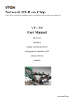
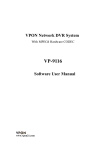
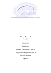
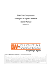
1
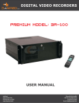
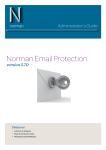
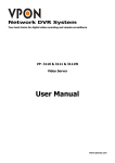
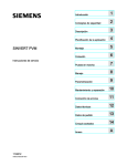
Network DVR System
Software User Manual
VP-504 / 508
VP-504H / 508H
Notice
The information in this manual was current when published. The manufacturer reserves the right to revise
and improve its products. All specifications are therefore subject to change without notice.
Note: Formosa21 will not be obligated to the responsibility outside the scope of VPON DVR.
Trademarks
VPON ® is a registered trademark of Formosa 21 Inc.
Microsoft, Windows, Internet Explorer ® are registered trademarks of Microsoft Corporation. Netscape,
Navigator, Communicator ® are registered trademarks of Netscape Corporation. Other brand and product
names referred to in this manual are trademarks or registered trademarks of their respective holders.
Trademarked names are used throughout this manual. Rather than place a symbol at each occurrence,
trademarked names are designated with initial capitalization. Inclusion or exclusion is not a judgment on the
validity or legal status of the term.
Warning
To reduce risk of electric shock, do not remove cover. No user service-able parts inside. Refer servicing to
qualified service personnel.
Do not expose this appliance to rain or moisture.
Do not install this product in hazardous areas where highly combustible or explosive products are
stored or used.
Severe impact or vibration may cause malfunction.
Do not move this product when VPON is working.
Position it in an open space with flat surface, and also maintain at least 15 cm between the left and
right sides of the body and the wall.
The lightning flash/arrowhead symbol, within and equilateral triangle, alerts the user to the presence of a
shock hazard within the product’s enclosure.
GUARANTEE
Every care has been taken in the preparation of this manual; if you detect any inaccuracies or omissions,
please inform FORMOSA21, INC, in Taiwan or your local distributor. FORMOSA21 cannot hold
responsible for any technical or typographical errors and reserves the right to make changes to the products
and manuals without your prior notice. FORMOSA21 makes no warranty of any kind with regard to the
material contained within this document, including, but not limited, the implied warranties of
merchantability and fitness for a particular purpose. FORMOSA21 shall not be liable or responsible for
incidental or consequential damages in connection with the furnishing, performance or use of this material.
Warranty does not cover
Damage caused by willful or accidental mishandling, removal of VPON warranty labels, environmental
conditions, including, electrical surges. Warranty will be voided if any of these conditions occur.
Important information
Before proceeding, please read and observe all instructions and warnings contained in this manual. Retain
this manual with the original bill of sale for future reference and, if necessary, warranty service.
When unpacking your VPON unit, check for missing or damaged items. If any item is missing, or if damage
is evident, DO NOT INSTALL OR OPERATE THIS PRODUCT. Contact your dealer or us for
assistance.
Table of Content
Initiation: VP-504(H)/508(H)Features/Notification/Specifications ………..1
Chapter 1: Introduction
1.1 VPON Main Features ………………………………………………………5
1.2 System Requirements ………………………………………………………6
Chapter 2: VPON network operations
2.1 First Time Step-by-step Setup ………………………………………………7
I. Connecting VPON to a PC for simple networking …………………………8
II. Default IP address of VPON ………………………………………………8
2.2 Surveillance screen panel …………………………………………………..11
2.3 Play button ………………………………………………………………….11
2.4 Exit button ………………………………………………………………….12
2.5 PTZ panel …………………………………………………………………..12
2.6 Setup button ………………………………………………………………...12
2.6.1 System Information ……………………………………………………12
2.6.2 Camera Setting ………………………………………………………...12
2.6.3 Audio Setting …………………………………………………………..13
2.6.4 Set Date and Time ……………………………………………………..14
2.6.5 Set NTP Server ………………………………………………………...14
2.6.6 System configuration …………………………………………………..15
2.6.7 Set Serial Ports ………………………………………………………...16
2.6.8 Set POS ………………………………………………………………..16
2.6.9 Alarm & Remote Control ……………………………………………...17
2.6.10 Set Name & On-Screen Display ……………………………………...18
2.6.11 Set User’s Authority ………………………………………………….18
2.6.12 DVR Setup ……………………………………………………………18
2.6.13 Record Schedule ……………………………………………………...19
2.6.14 Set Motion Detection …………………………………………………19
2.6.15 GPI Trigger Recording ……………………………………………….20
2.6.16 Set Pre-Alarm ………………………………………………………...20
2.6.17 Playback recorded files ……………………………………………….21
2.6.18 Search ………………………………………………………………...22
2.6.19 Send Mail …………………………………………………………….23
2.6.20 FTP Upload …………………………………………………………..23
2.6.21 Back to Home Page …………………………………………………..24
2.6.22 View Video Without Plugins …………………………………………25
Chapter 3 Graphic User Interface (GUI) for VPON
I. Graphic User Interface (GUI) ………………………………………………...26
II. GUI Functions Description …………………………………………………..27
1. “Play” Key Function ………………………………………………………...27
2. “Surveillance Screen Panel” ………………………………………………...28
3. “LIVE’ Key Function ……………………………………………………….28
4. “IO” Key Function …………………………………………………………..29
5. “GO TO” Key Function ……………………………………………………..30
6. “SET UP” Key Function …………………………………………………….31
[ System Setup ]
1) System Setup …………………………………………………………….31
2) Password Protect ………………………………………………………..32
3) Video ……………………………………………………………………..32
4) Disks ……………………………………………………………………...34
5) TV out ……………………………………………………………………34
6) OSD Text ………………………………………………………………...35
7) GPIO ……………………………………………………………………..35
8) PTZ Setup ……………………………………………………………….36
9) TCP/IP …………………………………………………………………..36
10) Account ………………………………………………………………….37
11) Audio ……………………………………………………………………37
12) Serial Ports ……………………………………………………………..38
13) System Info ……………………………………………………………..38
14) Date / Time ……………………………………………………………..39
15) ISP ……………………………………………………………………….39
16) Registry …………………………………………………………………40
17) Running Mode ………………………………………………………….40
18) Algorithm ……………………………………………………………….41
19) NTP Setup ………………………………………………………………41
20) License …………………………………………………………………..42
21) Default Settings …………………………………………………………42
22) Revise firmware ………………………………………………………..43
23) Reboot System ………………………………………………………….43
[ Record Setup ]
1) DVR Setup ………………………………………………………………44
2) Record Setup …………………………………………………………….44
3) GPI Trigger ……………………………………………………………...45
4) Pre-alarm ………….…………………………………………………….45
[ Alarm]
1) Alarm Setup ……………………………………………………………..46
2) GPI Alarm ……………………………………………………………….47
3) Motion Alarm …………………………………………………………...48
4) Video Lost ……………………………………………………………….48
5) Disk Space Low ………………………………………………………….48
6) Disk Error ……………………………………………………………….49
7) POS Event ……………………………………………………………….49
[ Motion Detection]
1) Motion Detection ………………………………………………………..50
7. “POS” Key Function ………………………………………………………...51
8. “Status” Key Function ………………………………………………………51
9. “Video” Key Function ………………………………………………………52
10. “PTZ Panel” Key Function ………………………………………………….53
11. “Play Panel’ Key Function ………………………………………………….54
VP-504(H)/508(H)
Features / Notification / Specifications
Removable Hard Driver initiation
When finished all connections for powering VPON, please be noticed that must turn on the
key of mobile rack before starting the Hard Disk usage.
VP-504(H)/508(H) control interface
GUI (Graphic User Interface) control.
CD-RW
Support IDE CD-RW
Watch Dog
Hardware Watch dog timer for automatic failure recovery
Watermark
Image safety verification system for protecting images from fraud.
Built-in web server
Users can do remote surveillance and function setups through IE browser to reach the
belonged web server.
GPI/O
8 in / 2 out (need I/O box)
VIDEO Input
VP-504 has 4 or 8 sets of Video Input port depending on the connections.
VGA Output & TV-Out
24 bit true color, and support NTSC/PAL composite video, RCA connector
COM ports
COM1 ports are for PTZ / POS / ATM.
VP-504(H)/508(H) Interface
1)VP-504(H)/508(H) Rear Panel
1
2) Digital I/O Box Connections
The digital I/O box is used to connect to alarm input and relay output.
I/O box(8 sensor input、2 relay output)
External alarm input: The I/O box allows 8 digital inputs for sensors, divided in 8 groups:
(IN1 GND1), (IN2, GND2), …, (IN8, GND8).
I/O Box
Sensor
IN 1
GND 1
Remark: For each group, IN and GND can be configured as Normal Open (NO) or Normal
Close (NC) in the software.
Relay output: The I/O box allows 2 digital relay outputs for alarm device (e.g. buzzer),
divided in 2 groups: (NC1, NO1, COM1) and (NC2, NO2, COM2)
The figure below gives an example for connecting a Buzzer to the I/O box. “DC power” is
an external power supply to the Buzzer. If the Buzzer is a NO device, you should connect it
to “NO 1” pin and leave the “NC 1” pin unconnected. If the Buzzer is a NC device, connect
it to “NC 1” pin and leave the “NO 1” pin unconnected.
I/O Box
Buzzer
- +
NC 1
NO 1
COM 1
- +
DC power
2
Specifications
Model
Video Stadard
VP-504/508
VP-504H/508H
Support NTSC / PAL Composite video
Video Input
4 or 8
Audio Input
1
VGA Output
24 bit true color
TV-Out
Support NTSC / PAL Composite video, RAC Connector
CD-RW
Support IDE CD-RW
3.5” drive bay
2
1
Max HDD
2
3
Sensor Input
Relay Output
Video Compression
8 in / 2 out (need I/O box)
Support H.263, M-JPEG, JPEG, MPEG4 standards
Image Size
Maximum Video
Recording
Playback Frame Rate
Maximum Live Display
Frame Rate
Browser Compatibility
Communication Protocol
Power Supply
Size
320x240 / 640x480
60fps
240fps(NTSC), 200fps (PAL)
Max.30fps for each channel
Win 98/ ME / 2000 / XP running MS IE 6.0 or above
Support TCP/IP, DHCP, NTP , HTTP , FTP
100-240 VAC, 50-60HZ
42.3cm (L) x 41.5cm (W) x 6.6 cm (H)
3
Chapter 1: Introduction
VP-504(H)/508(H) is a stand-alone Network DVR System. With 4 or 8 video input, one
audio input.It has Removable Hard Driver, CD-RW Driver for backup.VP-504(H)/508(H)
provides Graphic User Interface for operation. Watch Dog function for system automatic
failure recovery. The video also can display through VGA output in local. Besides, VP-504
(H)/508(H) supports digital recording function. It can record / playback / browse video
simultaneously and save video data by cycle recording to removable hard disk.
VP-504(H)/508(H) supports full motion live video footage with its corresponding audio
through the Internet, Intranet connection. Up to 4 or 8 cameras allow to be connected,
VPON deliver real-time full-motion audio / video transmission to anywhere anytime. All
that is needed is an Internet browser and our proprietary plug-ins software. Attached video
cameras can be remotely controlled to swivel and zoom in and out, and the unit can be
triggered to initiate certain events. VPON is a completely plug and play device getting up
and running as soon as possible without the need for ongoing maintenance or custom
hardware / software configurations. A sample configuration is shown below.
The installation is easy:
All you have to do is to plug the power and assign VPON an IP address for Internet
connection. Then, you can view the video through your browser, Internet Explorer at any
time, anywhere. It is perfect for factory/office monitoring, ATM surveillance, children care,
security system, tourism, sales presentation and more...VPON is the new era of the network
video transmission. It makes you see whatever you want easily!
4
1.1 VPON Main Features
Video & audio recording
Up to 4 or 8 camera inputs (color or B/W)
Up to 30 fps on each camera for local monitoring
Record / display / playback simultaneously
Built-in QUAD / MUX functions for local monitoring
Local playback of recorded video on VGA or TV monitor
Remote playback from PC browser
Query recorded data by date, time & events
Control well known brand PTZ Cameras
High video quality and low data rate
Up to 200:1 video compression
Multiple video compression engines: H.263, JPEG, M-JPEG, MPEG4
Network
Dynamic IP support for Internet access
Direct Dial-up available
Backup
Removable Hard Drives
Optional CD Writer
Easy to use
Embedded Linux OS and firmware in flash memory
Easy configuration via mouse, keyboard or HTTP
Standard web browser as the client application
Alarm function
Motion detection / Event trigger / Schedule / Pre-alarm recording
Voice Call, E-Mail & FTP alarm notification
Optional GPI/O for alarm control
Customization
Supports HTML file upload for home page customization
Supports FTP Server upload for customization
New product and new features
Point of sales DVR Integration
Low-bandwidth support
5
1.2 System Requirements
Composite CCD camera, V8 or camcorder… (NTSC or PAL standard)
The equipment for connecting to network:
1. Network mode: RJ-45 Ethernet network port connected to Internet and a public IP
address
2. Others: RS-232 Port and a serial cable for connecting to host PC.
3. A VGA monitor for display.
PC for the configuration / browsing
1. Pentium 4 CPU or better, desktop PC or notebook
2. 256 MB RAM or above
3. AGP VGA Card
4. Microsoft Windows 98/2000/ME/XP or above
5. Internet Browser (Microsoft Internet Explorer 6.0 or above)
6
Chapter 2: VPON Network Operations
2.1 First Time Step-by-step Setup
For first time startup, VPON is set to default value when it is delivered from factory.
The default settings of VPON are as following.
Running Mode
User’s Name
User’s Password
Administrator’s Name
Administrator’s Password
Custom Modem Init String (COM1)
COM1 Baud Rate (bps):
Video Encoding Algorithm
Set Video Resolution
Camera Control Device
Camera Control Timeout (Sec.)
Brightness
Contrast
Saturation
Hue
Quality
Compression Boost
Mirror Horizontally
Mirror Vertically
Auto Gain Control
Automatic
MAX connections for this camera
MAX bandwidth for this camera
(Bytes/sec)
MAX bandwidth of each connection
for this camera (Bytes/sec)
Audio Source
Microphone Gain
Speaker Volume
Microphone Control Timeout
Speaker Control Timeout
IP address
DNS IP address
Gateway IP address
Sub net mask
Motion Detection
Motion Detection Sensitivity
Running Mode
User’s Name
Password
Registry Server
Register HTTP Port
Registry Host Path
Visibility in Registry Server
7
Network Mode
WEBMONITOR
OYO
WEBMONITOR
OYO
Nil
115200
MPEG4
320x240
Nil
120
50
50
50
50
80
None
Unchecked
Unchecked
Unchecked
Unchecked
0
0
0
1
50
50
0
60
192.168.10.10
0.0.0.0
0.0.0.0
255.255.255.0
Enable
50
Network Mode
webmonitor
oyo
http://www.registry.nfic.com.tw/
registry.htm
Nil
cgi
Listed on Registry Server
Alarm Status (GPI )
Time Stamp
Time Stamp Format
Send Mail
FTP Upload
NO
Low center
MM/DD/YY
Disable
Disable
If you have a company or private Local Area Network (LAN) and want to connect VPON to
your network, it is recommended to test VPON at a separate network for verifying its
network operations and then modifies its network parameters to meet your LAN
environment. Steps as below:
I. Connecting VPON to a PC for simple networking:
Prepare a PC with LAN card or on board LAN and then connect it to VPON LAN port
using a crossed RJ45 UTP cable. This makes the PC and VPON in a small stand alone LAN,
has nothing to do with your existing LAN environment, as Fig 2.1.1.
Figure 2.1.1
Crossed UTP cable
Ethernet (IP address: 192.168.10.10)
Ethernet (IP address: 192.168.10.xxx)
II. Default IP address of VPON is 192.168.10.10. :
In order to access it , IP address of the PC has to be in the same LAN as VPON. It is
recommended to set IP address of the PC into 192.168.10.XXX, which XXX is within the
range of 0 to 255.
Please refer to steps below for modifying PC IP address under Windows OS:
1. Go to “Network” on “Control Panel” of the host PC.
Network
2. Choose “TCP/IP” and go to “Properties”
8
3. Change IP address of the host PC to: 192.168.10.20
4. Change Subnet Mask of the host PC to: And reboot the host PC.
255.255.255.0
Note: Please keep record for the original IP address and Subnet Mask.. After the
configuration of VPON is finished, you may want to fold back the host PC to its original
values.
5. Run a web browser and connect to http://192.168.10.10 (Or the IP address that you
changed). When it is connected, you will see a login dialog-box. Enter the default
Administrator’s name “webmonitor” and password “oyo”. Click “OK” button. Then you
will see the home page of VPON.
6. The first time you attempt to view the VP-504(H)/508(H) user interface using a web
browser, an ActiveX installation procedure will begin automatically.
9
When the following window appears. Click on the Download DCS.EXE” link.
7. The download will begin and the following window will appear.
8. Click Open to download and install the new plug-in. The download status is displayed
and you are prompted for an installation location.
9. Click OK to complete the installation. The following message will appear.
10
10. When installation is complete you will be able to view the VP- 504(H)/508(H) Home
Page.
2.2 Surveillance screen panel
The Surveillance Screen Panel is very similar to the one on the local GUI. See Surveillance
screen panel on chapter3.
There is no Sequence button one the network GUI. This feature is only available on the
local GUI.
2.3 Play button
Click the PLAY button to display a list of all the available recordings stored on the
VP- 504(H)/508(H) in a new browser window. Click List All to display the entire list.
From field
To field
Query button
List all button
Play file on this
time button
Search for files between particular times and dates by entering the dates in the To and From
fields and clicking Query. Click on a video recording to play it in a separate browser
window as following picture. Play a recorded video from a specific time and date by
entering the time and date in the From field and clicking Play file on this time and start to
play recording file.
11
2.4 Exit button
Click the Exit button to close the Home page.
2.5 PTZ panel
The network GUI PTZ panel is exactly the same as the local GUI PTZ panel.
2.6 Setup button
Click the SETUP button to display the setup screen.Use the setup screen to change user
definable parameters for the VP-504(H)/508(H). Choose a submenu from the list on the left
and click the link to display it.
2.6.1 System Information
Click the System Information link to display the System Information page.
This picture shows hardware I/O information and firmware version inside VPON.
2.6.2 Camera Setting
Use the camera Setting page to change the video settings for each of the connected cameras.
1.Video Source: Select Video Source input.
2. Brightness, Contrast, Saturation, Hue and Quality: You can set Brightness, Contrast,
Saturation, Hue and Quality here. These parameters are applied to all video sources. To
adjust brightness of each individual camera, please use “Gain Control” as described in
item 5 follows.
12
Brightness: The higher the brighter video
Contrast: The higher the stronger contrast
Saturation: The higher , the deeper color saturation
Hue: Effect on video color
Quality: The higher the better video quality
3. Compression Boost: Selection can be “None”, “Low”, “Medium” and “High” to adjust
video compression rate. The higher compression boost level,
the lower video data rate and the worse video quality.
4. Auto Gain Control: When this box is checked, VPON will keep the GAIN value
effective automatically no matter day or night, light or dark.
5. Mirror Horizontally: Check this option for video mirroring.
6. Mirror Vertically: Check this option to rotate the selected video source up side down.
7. Max connections for this camera: Limit the maximum connections allowed to access
this camera.
8. Max bandwidth for this camera (Bytes/sec): Limit the maximum bandwidth in
Bytes/second allocated to access this camera.
9. Max bandwidth of each connection for this camera (Bytes/sec): Limit the maximum
bandwidth allocated to each connection of this camera.
Click the “Done” button to save the new settings.
Note: Please click ”Write To FlashROM!” for permanent setting.
Note: 1) Value set at “Quality” level will be applied for all video sources. Other
parameters only apply to the camera chosen.
2) High quality level causes larger data rate for both storage & transmission.
2.6.3 Audio Setting
Use the Audio menu to set up the audio parameters for the VP-504(H)/508(H). You can set
following parameters:
1. Audio Source: Select an audio input and output source.
2. Microphone Gain : Adjust Microphone gain of Audio input .
3. Speaker Volume : Adjust Speaker gain of Audio output from VPON.
13
4. Microphone Control Timeout:There is only a user can control microphone at a time.
This timeout value limits the maximum period in seconds that user can own the right
without any bother except that from the administrator. Once timeout, anybody can
request to gain the control right of Microphone except the original owner.
5. Speaker Control Time out:Same function as Microphone time out.
The Audio operation interface:
Bandwidth used
Speaker Volume
PC Microphone ON/OFF, click to open
Save audio data to file
2.6.4 Set Date and Time
Use the Set Time and Date page to set the time and date. Select a time zone from the drop
down menu and enter new local time and date using the keyboard. Click Done when all
fields are updated. Click Undo to revert to original settings. If you change the time zone, the
system will reboot.
2.6.5 Set NTP Server
1.Use the Set NTP Server page to set parameters for a NTP (Network Time Protocol) server
to synchronize the device time with the atomic clock. Select a server and enable it using the
drop down menus. Enter a time period using the keyboard to indicate the period after which
the time is re-synchronized. Click Done when all parameters are entered correctly. Click
Undo to revert to original settings.
14
2.6.6 System configuration
Use the System Configuration page to set the following parameters for the VP- 504(H)/
508(H).
*Running mode - sets the operation and control mode.
*TCP/IP setting
Key in all of the TCP/IP setting, including IP Address, Gateway IP Address, Subnet Mask,
and DNS IP Address. To gain IP address from a DHCP server, you can assign the IP
address of VPON to be 255.255.255.253.
Note: 1.DNS IP address must be assigned if a domain name other than an IP address is used
as a server’s address in the following fields: “Registry Host Address” in System
Configuration Page, “E-Mail Server” in E-Mail setting, and “FTP Server” in FTP Upload
setting.
2. For users with ADSL/Cable Modem, please refer to the chapter “VPON advance
networking” .
*ISP setting
Sets up dial-up parameters for sending E-mails.
*Account Setting
Set user’s and administrator’s login name and password. Keeping these fields empty will
cause VPON skip checking the authority. The ‘Set User’s Authority’ Page only takes
effective when the user’s name and password are not empty here.
*COM1 Port Setting
COM1 is default for modem connection. You can select it as “modem”. COM1 is a RS232
interface and default for PTZ control. You can select it as “PTZ Camera Control” device.
*Set Video Compression Algorithm & Resolution
Select one of four Compression algorithms. There are H.263, JPEG, Motion-JPEG and
MPEG4. Set Video resolution 320x240 or 640x480.
Click the “Done” button and go back to the home page of VPON.VPON will save these
parameters and reboot. During the period of rebooting, VPON will not transmit any video.
15
*Set Camera Control
Select PTZ camera models from the list. There are VP-202, VP-203, Cannon VCC3/VCC4,
Li-lin PIH-717X, Acqutek DOM 1200A and Pelco D type camera. This list grows once a
while when RD release new supporting models. You shall check which camera numbers that
device hooked to (from 1 to 6) and the timeout of exclusive control right. At a given time,
there is only one user can control the camera connected to VPON. This time-out value is the
maximum period in seconds the user can own the right without any interrupt except coming
from the administrator. After the time expired, the exclusive control right will grant to the
others.
*Set IP Registry Host IP Address & Path
These settings are ONLY useful when the IP address assigned to VPON is NOT a static IP.
2.6.7 Set Serial Ports
The VP-504(H)/508(H) can be connected to other serial devices such as external modems,
GPIO (General Purpose Inputs and Outputs), Voice Call devices, PTZ cameras, camera
control devices, text input devices, using serial ports –COM1.Use the Serial Ports menu to
set the following parameters:
2.6.8 Set POS
Use the Set POS page to set the color and font size for each of the connected cameras. Use
the Serial Ports menu to set the following parameters. Click the “Done” button to save the
new settings.
16
2.6.9 Alarm & Remote Control
GPI devices will show NC (normally closed ) or NO (normally open) as the status of the
switch. Depending on the input, you can change the status of the GPO devices on On or Off
as required.
2.6.10 Set Names & On-Screen Display
1. You can choose the item "Set Names and On-Screen Display" from VPON home page
to enter this page. You can set the server name if you have multiple VPON on network.
You can also set camera names to indicate the physical location of the cameras or any
identification for easy understanding.
2. You can set overlay text strings in English for each camera and this string will be
overlaid directly on the video like time-stamp. You can specify the content and position
of this text
3. On this page, you can also set the position of the time stamp of each camera. There are 4
pre-defined positions, just select the position you like. You can set Timestamp Date
Format as MM/DD/YYYY ,DD/MM/YYYY or YYYY/MM/DD in this page also.
17
2.6.11. Set User’s Authority
Use the Set User’s Authority page to set the individual privileges of up to 256 users. Enter
the user number in the user field. Assign a name and password in the respective fields. To
restrict users from viewing particular cameras, select the required cameras from camera 1~8.
Enable Camera Control , Audio and playback of the video recording as needed.
2.6.12 DVR Setup
Use the DVR Setup page to set the recording mode to either Auto stop (stops when disk
space runs out) or Cyclic Recording (overwrites oldest recordings when disk space runs out).
18
2.6.13 Record Schedule
Use the Record page to set up to 16 automatic recording schedules. For each record
schedule, select the day and start and stop times for recording. For each camera, select off,
Normal Recording, Motion Detection Recording , GPI Trigger Recording or MD& GPI
Trigger Recording to record only when motion is detected. Enable Audio if you want to
record audio also. Weighted recording is setting special recording frame rate when an alarm
of one of camera was triggered. Select a Frame Rate of recording for each camera.
Weight recording
2.6.14 Set Motion Detection
a)You can enable or disable the motion detection function of one camera. If enabled, a 8x8
red block will be displayed on the top-left corner of the video window when motion
detected.
b)Set the sensitivity of camera, the value of sensitivity from 5 to 100. For indoor camera,
sensitivity setting is about 20.
c)Enable “Show Detect Area” will make the video inside the detection area becomes lighter.
It is convenient for configuration purpose.
You can move or change the detect area via mouse movements or key in X,Y Position
directly.
19
2.6.15 GPI Trigger Recording
Use the GPI Trigger Recording to set up to 8 automatic GPI recording schedules. Clink the
“Enable” item box to start the GPI Trigger, and then set the timetable for recording the
Trigger. Click “Done” button to save the new setting.
2.6.16 Set Pre-Alarm
On the left side of VPON main page, click “Pre-Alarm” to set pre-alarm function When
enable this function, VPON will record camera video before triggered event happens or
motion detects.
You can set the numbers of frames to be recorded for camera 1 to camera 8, then click
“Done” button to save the setting values.
20
2.6.17. Playback recorded files
The playback page enables you back a video recording of your choice. Specify the day and
time in the To and From fields and click the Play file on this time. Field to play back files in
the specified time duration. Click List All to list all recorded files. Click Query to Search for
a particular file based on Event or Text. Click a file to play it back.
1. Download & Save
You can download and save video data as a new file in a remote client PC. from the remote
playback screen. Please click “Download &save” and give a file name for it. As this
function downloads video through LAN or Internet, it takes time if bandwidth is NOT good
enough.
2. “320x240” - You can select 320x240, 640x480, 800x600, or 1024x768 different
resolution for play back videos.
3. “Camera 1(2,3,4)” - Users can select the video sources from Camera1, Camera2,
Camera3, Camera4 or All cameras to play the recorded data.
4. Scroll Bar - When you moves the scroll bar backward and forward to the position that
you want to play .
5. “Save” - Click “Save” icon to save the recorded video as a new file.
6. “Snapshot” - Click “Snapshot” icon to take the image snapshot from video screen.
7. “Play” - Click “Play” icon to start playing the videos.
8. “Play Forward” - Click “Play Forward” icon to advance the video.
21
9. “Stop” - Click “Stop” icon to stop playing the video.
10. “1x” - You can select playing speed of Full speed, 2x, 1x, 1/2x, 1/4x, 1/8x.
11. “Source” - You can select the file status from “Source”, “Motion”, or “GPI” to play the
recorded data.
11-1 “Video Source” - When selecting “Source”, VPON will play the recorded video from general
camera sources.
11-2 “Motion Detection” - When selecting “Motion”, VPON will play the recorded video
from videos recorded by motion detection.
11-3 “GPI Trigger” - When selecting “GPI”, VPON will play the recorded video from
videos recorded by event trigger.
2.6.18 Search
Search video clips based on text (POS transaction data)
1. Click search button and enter the submenu.
2. You can search by any keyword base on POS transaction data(text).
3. If you want to find out data faster, we recommend you to narrow down searching day,
time and cameras to get faster response.
4. Press Query button when done to conduct the search.
POS Text
22
2.6.19. Send Mail
The VP-504(H)/508(H) can send a snapshot by E-mail when triggered by an alarm. Use the
Send Mail page to set E-mail details for each camera.
Select GPI or motion
detection to trigger
Put e-mail address
h
Select the camera
image to attach
Enable here
Under the Individual Settings, specify the type of event that causes the E-mail to be sent in
the Type field by choosing Motion Detect or GPI. Fill in the start and stop times for
monitoring the alarm, the recipients, subject and content of the E-mail. Enable a snapshot of
the camera video to be attached to the E-mail by selecting cameras in the Snapshot option.
Under the Global Settings, fill in the mail server details. Fill in the details using mouse and
keyboard and click Done when complete.
Note: If you set a domain name in the mail server setting, provide the DNS IP address
in the System Configuration (see System configuration ).
2.6.20 FTP Upload
The VP- 504(H)/508(H) can upload snapshots from the camera using FTP to a predefined
location in the event of an alarm. Use the FTP Upload page to set FTP details.
23
Under the Individual Settings, specify the type of event that causes the E-mail to be sent in
the Type field by choosing Motion Detect or Continuous. Fill in the start and stop times for
monitoring the alarm, the file name and directory for FTP. Enable a snapshot of the camera
of video to be uploaded by selecting cameras in the Snapshot option.
Note: If you specify a file name, each time a file is uploaded it will overwrite the
previous file with another of the same name. If no file name is specified, a new file will
be written each time with a new filename based on the time and date.
Under the Global Settings, fill in the FTP server, account, password, and port number.
Fill in all the details using mouse and keyboard and click Done when complete.
2.6.21 Back to Home Page
The Back to Home Page link will redirect you back to the VP-504(H)/508(H) home page.
2.6.22 View Video Without Plugins
You can view video even if the machine you are working on does not have the plug-ins necessary
for full functions. Click the view Video Without Plug-ins link to view the video page without plugins.
24
You will need to enter an administrator user name and password to view without plug-ins.
25
Graphic User Interface (GUI) for VPON
Chapter 3:
Graphic User Interface (GUI)
I.
VPON GUI (Graphic User Interface)
Date/Time
Hard Disk Space
I) Play II) LIVE III) IIO
IV) GOTO V) POS
VI) SETUP VII) VIDEO
PTZ Control Panel
SET:
Set PTZ Camera Position
(6 sets)
Call : Call Set Surveillance
Position (6 sets)
Zoom In/Zoom Out
Focal Length
PTZ Control
A B C
D E F
1
2
3
4
5
Adjust Movement
Speed
Up/Down
Left/Right
Figure 3.1
G
Figure 3.1 Description
A)
B)
C)
D)
E)
F)
G)
Single Screen
QUAD
8 Splits
Previous Page
Next Page
Sequence show
Camera
1)
2)
3)
4)
Brightness
Contrast
Saturation
Hue
5) Quality
I)
II)
III)
IV)
V)
VI)
26
PLAY :Play back file
LIVE :View live screen
IO: GPIO setup
GO TO :Search recorded file
POS: Superimpose POS
transaction data onto
corresponding video
SET UP: System setup
II. GUI Functions Description
1.
“Play” Key Function
Press “Play” key to playback a recorded file. A window will pop up on the screen display a
table of the recorded files in a list of one file per hour.
Select the desired time slot and press “OK” key to start playing the recorded data. Please
see Figure 3.2.1.
Screen Description: The “Play” Screen of the Recorded File
Figure 3. 2.1
Fields of the file table includes:
(1) Lock (L) -- A “*” indicates this file was locked. A locked file cannot be deleted or over
written.
(2) Date/Time -- Indicate the date & time this file was created.
(3) Motion Detection (M) -- A “M” indicate this file was created by “Motion Detection”.
(4) Alarm for GPI Trigger (A) -- An “A” indicated this file was created by “Alarm Trigger”.
(5) File Size (MB) -- File size in MB.
The main function of the “Play” key is to playback recorded files. The recorded files are
created in the unit of one hour. Each hour at least includes one file and is listed according to
time sequence of files. Time sequence allows users to access their desired files for playback.
The users only need to click the file they want to and the recorded videos of that time slot
will be played on the screen automatically.
Users may click the “CD-R Backup” button to burn a copy of one particular file. Users
may also click the “Lock” button to enforce the protection to one particular file to avoid
over written due to insufficient hard-disk space.
27
2. “Surveillance Screen” Panel
The surveillance screen’s selection panel includes screen segment selection, previous/next
screen, switch channel, and camera connection status. See Figure 3.2.2.
A
B
C
D
E
F
Screen Segment Selection,
Previous/Next Page, and Sequence
Show
Numbering Status and Selection of
Connected Camera
G
Figure 3. 2.2
Function Selection:
(A) Full Screen
(B) QUAD
(C) 8 Splits
(D) Previous Page
(E) Next Page
(F) Sequence Show
(G) Camera Number
The menu of the surveillance screen is located at the lower left of the screen.
See Figure 3.2.3.
Figure 3.2.3
3. “LIVE” Key Function
Press the “Live” key directly to show the live video at the camera site. Users can view the
live video from the surveillance screen. See Figure 3.2.4.
28
Description: a 4-screen segment.
LIVE
Figure 3.2.4
4. “IO” Key Function
Press the “IO” key at the button of the screen to immediately show the “GPIO Control
Panel”.GPIO (General Purpose In/Output) device can be connected to an external alarm
system. Users can understand the status whether the alarm was triggered according to the
indicating light shown on the GPIO control panel. See Figure 3.2.5.
The I/O box allows 8 digital inputs for sensor, divided in 8 groups; (IN1 GND1), (IN2,
GND2), …..(IN8, GND8 ). The following figure shows an example of one sensor
connecting to the first D1 (IN 1 and GND 1 ) of the I/O box. Suppose the Sensor is a
“normal-open (NO)”, device, so you configure DI 1 as “NO” in the software. Now when IN
1 and GND 1 are short-circuited, I/O box will send an alarm signal to the DVR.
You can do the same to the other 7 groups of DI.
IO
Active GPI (Input) and GPO
(Output) points depend on the
IO module connected
Figure 3.2.5
Note: The GPIO module of the VP-504(H)/508(H) has “8 GPI” points and “ 2GPO”
29
points.
Function of the GPI Indicating Light:
1. First Row of GPI: Indicating light will be ON immediately when the alarm is triggered.
The staff at the site can see the alarm light on the screen within the shortest time, and the
light on the first row has the prompt reporting function.
2. Second Row of GPI: After the alarm on the first row goes off, the light on the second
row will then be ON. By seeing it, the patrol staff knows that an alarm has been triggered
and then take proper actions such as review the recorded file to understand the situation at
that time.
Function of the GPO Indicating Light
The staff at site can select and click the indicating light to turn on/off the GPO points
directly for external devices control.
5. “GOTO” Key Function
This key provides the function for users to search recorded file by time. You can search by
Time, by Event or by Text. Enter year/month/date, hour/minute/second, and then press
“OK” to playback the recorded video at that time. That is, users can playback the recorded
file by providing a specific time. Please see Figure 3.2.6.
! Press “GOTO”
! Key-in the search time; for example, 2003/8/20/14:10:22
Figure 3.2.6
! Press “OK” to replay the recorded data. See Figure 3.2.7.
30
Figure 3.2.7
6. “SET UP” Key Function
【System Setup】
The setup contents of the VPON system include parameters of the system setup, record
setup, alarm and motion detection. Please see Figure 3.2.8.
! Press “SET UP”, the system set-up screen will appear.
Figure 3.2.8
System Setup:Items in this selection are as below.
1) Password Protect
8) PTZ Setup
2) Video
9) TCP/IP
3) Video input
10)Account
4) Disks
11)Audio
5) TV Output
12) Serial Ports
6) OSD Text
13) System Info
14) Date / Time
7) GPIO
31
15) ISP
16) Registry
17) Running Mode
18) Algorithm
19) NTP Setup
20) License
21) Default Settings
22) Revise firmware
23) Reboot system
Password Protect:
The Password Protect screen helps you to enable password protection, set administrator and
user passwords, set the auto lock period and lock the system immediately. Enabling
password protection prevents unwanted users from accessing or configuring the VP-504(H)
/508(H).
Enter new passwords for Admin and User in the corresponding fields. Set an auto lock time
if required in the Auto lock after field. The auto lock function locks the system after a given
time and a password is required to unlock it. Click Lock Now! to lock the system
immediately.
Note: If you do not have a keyboard connected to the system, you can use the on-screen
keyboard to enter your passwords. All the fields that can be edited using the on-screen
keyboard are indicated by the on-screen keyboard icon. Double-click the field to display the
on-screen keyboard. Use the mouse to enter characters for the required field.
Video:
The Video menu enables you to set video parameters such as the video standard and so on
for each of the connected cameras.
32
Standard: sets the video signal format. Choose NTSC in the US, or PAL in Europe and
most Asian countries. If you are not sure about this option, select Auto.
VP- 504(H)/508(H )will detect the video standard automatically.
Brightness: adjusts the amount of light or brightness for the selected camera according to
your preference.
Contrast: adjusts the difference between light and dark areas or contrast for the selected
camera according to your preference.
Saturation: adjusts the amount of color for the selected camera.
Hue: adjusts the dominant color for the selected camera.
Quality: adjusts the video quality for each camera. The default setting is 80. We
recommend that you do not set this to 100 to avoid a slower rate of video transmission and
using up a significant amount of hard disk space.
Compression Boost: enables you to compress the video signal to save disk space and thus
extend recording time. It is recommended to keep this setting to None. The higher the
compression boost, the lower the video data rate. For a significantly lower data rate, we
recommend you use the H.263 algorithm.
Auto Gain Control: enables automatic gain control to adjust the video signal strength.
Mirror Horizontal: flips the video signal from the selected camera along the horizontal
axis.
Mirror Vertical: flips the video signal from the selected camera along the vertical axis.
Max Connection: limits the maximum number of connections allowed to access the VP504/504H over the Internet. Set to zero to allow the maximum number of connections.
Max Bandwidth: sets the maximum bandwidth in bytes/second that can be used by users
connecting to the VP- 504(H)/508(H) over the Internet.
Max Conn. Bandwidth: sets the maximum bandwidth allocated for each connection to the
VP- 504(H)/508(H). This is the maximum bandwidth divided by the maximum connections.
Local Display: enables viewing the selected camera video signal on the local display. If this
option is set to Off, the camera is still optional and its video can be recorded if needed.
Video Input:
Use the Video input menu to assign a number to each camera connected to the VP-504
(H)/508(H).
33
Usually you will want to call the camera connected to port 1, “Camera 1” but you could
assign it any number between 1 and 8.
Disks:
Use the Disks menu to configure network disks that the VP-504(H)/508(H) uses to record data. If
no disk is connected, (No Device) appears in the Disk Device field.
TV output:
Use the TV Output menu to configure the video output for the VP-504(H)/508(H). The
VP-504(H)/508(H) can support standard VGA computer monitors or TV type screens. Set
the Camera (From) and Camera (To) options to specify the range of cameras that are
displayed in the cyclic display mode.
Note: The video could be displayed by the VGA computer monitors and TV type screens at
the same time, but the images will be affected on the VGA computer monitors.
34
OSD Text:
Use the OSD Text menu to assign text for each of the connected cameras. For instance, you
may like to have text Saying “c1” on the image from a camera installed in the c1.
To display the OSD text:
1. Select the desired camera from the Camera drop-down box.
2. Click the Enable field to display the text.
3. Adjust the position of the text displayed on the image using the X and Y parameters. A
value of X=0 and Y=0 would result in the text appearing at the top left corner of the
camera image. Increasing the value of Y moves the text down the screen. Increasing
the value of X moves the test to the right. Enter the text to be displayed in the Text
field.
4. Use the mouse to complete the fields and click OK to save changes.
GPIO:
The GPIO (general purpose input output) menu enables you to view the status of the input
and output devices such as switches, sensors, LEDs, and so on and view their status. These
35
devices can be attached to the unit to turn external alarms (outputs) on or off when the
specified input changes. When an alarm has been triggered, the GPI and GPO that are
connected will show the status of the input or output device. GPI devices will show NC
(normally closed) orNO (normally open) as the status of the switch. Depending on the input,
you can change the status of the GPO devices to On or Off as required.
Change the GPO status as needed. Make sure that the devices are working by checking the
actual physical status of the inputs and outputs after making changes in this menu.
NOTE: Enable GPIO function may cause system efficiency drop down.
PTZ Setup:
Use the PTZ (Pan, Tilt, Zoom) Setup menu to set the type of PTZ camera. Select the type of
PTZ cameras used and set each camera that has one connected to Yes. The timeout value
represents the time given to the cameras to respond a command.
TCP/IP:
Use the TCP/IP menu to enter TCP/IP address details for the VP-504(H)/508(H).
36
Account:
Use the Account menu to set up an administrator name and password as well as the super
user name and passwords. You can also use this menu to set up to 256 additional users, their
passwords and their permissions on the system. Select the user number and assign a Name
and password to it. Click the PTZ, Playback, and Audio fields to enable access to these
properties for the selected user. Select the cameras that you want the user to have access to
and set them to Yes.
Note: It is important that you set up the super user name and password. The super
user is different from the administrator and has access to only live videos and playback
files. Use the More Users field to change the authorities of Internet users. Use the
keyboard or mouse (recommended) to complete all the fields and click OK to save
changes.
Audio:
Use the Audio menu to set parameters such as Mic Gain, Speaker, Mic Timeout and Speaker
Timeout. You can also perform a self test to test if the microphone and speaker are working
correctly.
37
Serial ports:
The RS232 serial ports (COM1) is used to attach PTZ camera control cables, external
modems, or Data Capture to the VP-504(H)/508(H). Use the Serial Port menu to set
parameters for the serial ports.
System info:
Use the System Info menu to display the system information such as disk parameters,
TCP/IP properties, firmware information, and so on, on the screen.
38
NOTE:There are no configurable fields on this page. Click OK or Cancel to leave the
screen.
Date/Time:
Use the Date/Time menu to set the precise time and date on the system. You can also set the
local time zone in the T.Zone field.
ISP:
If you are using dial-up access to the Internet, use the ISP menu to enter details of your
Internet Service Provider. Use the mouse to complete all fields and click OK to save
changes.
39
Registry:
The Registry menu enables you to set up the registry server for your device. If you are using
a dynamic IP address for the VP-504(H)/508(H), you can set up the device to post its IP
address to the VPON registry server. You can then look up your IP from the MAC address
or server name. You can use the registry server to give a name to the VP-504(H)/508(H)
also.
Running mode:
Use the Running Mode menu to switch between Network Mode and ISP Mode.
40
Algorithm:
Use the Dimension option to set the resolution of the video (320x240 or 640x480). We
default resolution setting is 320x240. Use the Algorithm option to set compression standard
of the video (H.263, MPEG4, JPEG or M-JPEG). The default compression is MPEG4.
NTP setup:
Use the NTP Setup menu to enter details of the Network Time Protocol (NTP) server used
to synchronize the time of the device with the network.
41
License:
The function of POS will be activated after input the license key. Click the Register button
when you see the “#POS” , it mean register successful.
Note: The license in the following is an example only. Each DVR should have different
license number. Please contact us for get a license.
Default settings:
Use the Default Settings menu to reset all configurable parameters to their factory default
settings.
Click Restore Defaults? (Yes/No) to restore defaults. Click Cancel or No to retain the
current settings.
42
Revise firmware:
Use the Revise Firmware menu to upgrade the VP-504(H)/508(H) firmware.
Click Revise Firmware?(Yes/No) to start the firmware upgrade process. Click Cancel or No
to abort the attempt.
Reboot system:
Use the Reboot System menu to reboot or shutdown the system.
43
【Record Setup】
! Click the “Record Setup” option in the system setup to show the screen as shown in
Figure 3.2.9.
Figure 3.2.9
DVR setup:
Use the DVR menu under the Record Setup tab to set the Digital Video Recorder
parameters.
Select either Auto Stop or Cyclic Recording. Auto Stop recording stops when disk space
runs out. Cyclic Recording continues to record until disk space runs out and then overwrites
the oldest records. Click OK to save changes.
Record schedule:
Use the Record Schedule menu under the Record Setup tab to set up automatic recording
schedules for each camera and audio. You can set up to 16 record schedules that
automatically record at given times and days even frame rate just remember to close auto
speed setting. Weighted recording is setting special recording frame rate when an alarm of
one of camera was triggered.
44
GPI Trigger:
Use the GPI Trigger menu under the Record Setup tab to enable recording video from
specified cameras when triggered by an external alarm (GPI) connected to the system. For
instance, you may want to record video from a camera installed at your front door when the
door lock is opened. In this case, connect an alarm module (not provided) to lock and set the
front door camera to start recording.
Pre-alarm recording:
Use the pre-alarm menu under the record setup tab to determine how many frames are
record before an alarm event occurs. Each camera can be set separately and you can record
up to 300 frames.
45
【Alarm】
Alarm setup:
Use the Alarm Setup menu under the Alarm tab to define what action is taken when an
alarm is triggered. Through this menu, you can set up an E-mail address to which an E-mail
is sent when the alarm is generated, or set up the device to display a video popup message
on your monitor, or place a voice call.
The Voice Call options enable you to set up a voice modem that will make a call when the
selected event (such as a GPI alarm, or video lost from a camera) occurs. Set the following
options:
Redial - sets the number of times the voice modem will redial
Voice Repeat - sets the number of times the voice message is repeated on the voice call
Rec. Time - sets the time for which audio is recorded
Modem Speaker - sets the internal or external speaker to be used
Voice File - selects the voice file to be sent
Edit File Name - enables you to change the file name of the voice file
Use the keyboard or mouse (recommended) to complete all fields and click OK to save
changes. Refer to the following sections to see how to select the voice call as the action for
specific events such as GPI alarm and so on.
46
Note: The Voice Call options will be grayed out in the menu system if the voice modem
function is not selected in the serial port setup menu. Make sure that a voice modem is
enabled in device field in the Serial Ports menu item in order to place voice calls.
『Voice call features』
A voice call message can be recorded using an internal or external microphone, and can
be played back using an internal or external speaker.
Up to 60 voice messages can be recorded and stored on the VP-504(H)/508(H) and
used for different alarm events.
Messages recorded for the voice call function must be between 5 and 10 seconds.
『Known issues with the voice call function』
There will be three seconds silence between a voice call being answered and the start of
the message.
If the voice call function calls a phone with an automatic answering machine, the
VP-504(H)/508(H) will behave as if the phone has been answered.
The VP-504(H)/508(H) does not support non-standard ringing tones. If the VP-504(H)/
508(H) calls a phone and an unexpected tone is received, an error message will be
generated.
GPI alarm:
Use the GPI Alarm menu under the Alarm tab to set what actions are taken when a GPI
alarm is generated. You can set up the alarm through a message, a beep, a video popup, a
voice call or E-mail.
Use the keyboard or mouse (recommended) to select the required GPI from the GPI
drop-down box and complete all fields. For each action, you can specify the time interval
over which the GPI is monitored for an alarm to be generated. For the Voice Call option,
specify two telephone numbers where the call may be placed along with the voice file. For
the E-mail option, specify the recipient, subject, and text of the E-mail along with which of
the cameras.” status” is sent in the E-mail and the start and stop times. Click OK to save
changes.
47
Motion Alarm
Use the Motion Alarm menu under the Alarm tab to set what actions are taken when a
motion detection alarm is generated. You can set up the alarm through a message, a beep, a
video popup, a voice call, or E-mail.
Video lost
Use the Video Lost menu under the Alarm tab to set what actions are taken when video
signal from a camera is not available. You can set up the alarm through a message, a beep, a
voice call, or E-mail.
Use the keyboard or mouse (recommended) to select the required camera for video lost from
the Camera drop-down box and complete all fields as described in GPI alarm. Click OK to
save changes.
Disk space low
Use the Disk Space Low menu under the Alarm tab to set what actions are taken when the
disk space is insufficient to record data. This alarm is generated only when the DVR mode
48
is set to Auto Stop. You can set up the alarm through a message, a beep, voice call, or
E-mail.
Disk error
Use the Disk Error menu under the Alarm tab to set what actions are taken when there is an
error while accessing the disk. You can set up the alarm through a message, a beep, a voice
call, or E-mail.
POS event
Select the POS event function and start to sep up reaction when receiving the text data from
POS machine. You can set up the alarm through a beep, a voice call, or E-mail.
49
【Motion Detection】
!Click the “Motion Detection” option in the figure and the screen will show as
Figure 3.2.10.
1
2
3
4
Figure 3.2.10
Motion Detection Setup Procedure
1. Camera: Select the camera for setting motion detection
2. Enable (Yes/No): Turn On/Off the motion detection.
3. Sensitivity: Select motion sensitivity level .
4. Directly drag the square on the screen to a desired size & location for
Motion Detection.
Each small square on the displayed grid can be set to detect motion. Use the left mouse
50
button to make a square sensitive to motion. Use the right mouse button to make it
insensitive. Click OK to save changes.
7. “POS” Key Function
!Click the “POS Key Function in the figure and the screen will show as Figure
3.2.11.
!After the “POS” key is pressed, the POS screen will appear at the lower right of the
screen.
!Record and associate POS transaction data with video.
Figure 3.2.11
8. “Status” Key Function
The “Status” key provides the status of the recorded data, motion detection, remote control,
and recording progress to users. Please see Figure 3.2.12.
! After the “Status” key is pressed, the Status screen will appear at the lower right of the
screen.
51
Figure 3.2.12
! Users can know current recording and file status from the Status panel.
Following status are displayed:
Data:
shows the time and area of the recorded data during the recording
period.
Motion: shows the location where motion detection was triggered during the
recording period.
GPI:
shows the location of triggered GPI during the recording period.
Progress: displays current playing progress.
9. “Video” Key Function
The “Video” keys are used to adjust brightness, contrast, saturation, hue, and quality of
video. Drag the adjusting bar Up and Down to change the corresponding values of each item.
Please see Figure 3.2.13.
! After the “Video” key is pressed, the Video control screen will appear at the lower
right of the screen.
52
(1) (2) (3) (4) (5)
Figure 3.2.13
! Drag the following items with the mouse to adjust the desired value.
(1) Brightness
(3) Saturation
(5)Quality
(2)Contrast
(4)Hue
10. “PTZ Panel” Key Function
PTZ ( pan/ tilt /zoom ) Control: It is a remote camera control. Users can control the
surveillance screen through the remote camera (PTZ) lens aiming at the preset monitoring
position of the PTZ camera or the monitoring angle of the camera for adjustments, such as
Zoom in/out, Focus in/out, and moving UP/DOWN/Left/Right to adjust and determine the
monitor setup.
! PTZ Panel is located at the right side of the screen as shown in Figure 3.2.14.
53
PTZ Setup
Preset points
Recall points
Zoom In/Out
Focus
Moving Speed
Select
Figure 3. 2.14
To setup preset positions
Move camera to the position you want and then press the number under “Set” to save it
as pre-set point. There are 6 pre-set points.
To call back preset positions
Press a number under “Call” to position the camera to previous preset point. There are
6 re-call points.
Zoon In/Out Adjustment
Click the “+” end to zoon in and “-“ end to zoom out camera lens.
Focus In/Out
Click “+” or “-“ to adjust camera focus.
Moving speed selection
On Fig 3.2.14, the selection dot lights at middle position. This means when click
The Up/Down/Left/Right keys under it, the camera movement will be in middle speed.
If the dot lights at right hand side, the speed will be fast. If at left hand side, it will be slow
movement.
Camera Position control
This is done by click the Up/Down/Left/Right arrow keys to make the camera moves to
the desired position.
11. “Play Panel” Key Function
The “Play Panel’ keys allow users to select one of the followings to search their desired
images by playing recorded files. They are “Play Previous/Next Screen”, “Playing
Speed”, “Play”, “Pause”, “Stop”, Fast Forward/Rewind.” Please refer to Figure 3.2.15.
54
(1)
(2)
(3)
(4)
(5)
(6)
(9)
(10)
(12)
Figure 3.2.15
(7)
(14) (11) (13)
(8)
Functional Description
(1) Date & time indicator -- The minute & second indicator here will vary
with the playback progress.
(2) File size of current playback file
(3) Play back speed indicator – Indicate current playback speed
(4) Step forward & reverse keys – One click steps one frame
(5) Play back speed selection dot – The dot lights after selected this speed.
Dots at clockwise are faster speed, those at counter clockwise are for
Slower speed
(6) Pause key – Click to pause the playback
(7) Fast forward – Click & hold to proceed fast forward
(8) Stop – Stop the playback. The playback will re-start from beginning if it is
Stopped & then play again.
(9) Play – Click to playback
(10)Fast reverse – Click & hold to proceed fast reverse
(11)Current playback position indicator – Indicates the position in the file that
current video screen relates to.
(12)GPI Trigger indicator – Indicates the position that received GPI triggers
(13)Motion detection trigger indicator – Indicates the position that motion detection occurs
(14)Recorded data indicator – When there is white bar on the graph, there is
recorded data in that position. When there is dark, that means no
video is recorded.
55