1
CC-Link Safety System Master Module
User's Manual
-QS0J61BT12
SAFETY PRECAUTIONS
(Always read these instructions before using this equipment.)
Before using the product, please read this manual, the relevant manuals introduced in this manual,
standard PLC manuals, and the safety standards carefully and pay full attention to safety to handle the
product correctly.
In this manual, the safety instructions are ranked as "
WARNING" and "
CAUTION".
WARNING
Indicates that incorrect handling may cause hazardous conditions,
resulting in death or severe injury.
CAUTION
Indicates that incorrect handling may cause hazardous conditions,
resulting in minor or moderate injury or property damage.
Note that the
CAUTION level may lead to a serious consequence according to the circumstances.
Always follow the instructions of both levels because they are important to personal safety.
Please save this manual to make it accessible when required and always forward it to the end user.
A-1
[Design Precautions]
WARNING
When a safety PLC detects an error in an external power supply or a failure in PLC main module, it
turns off all the outputs.
Create an external circuit to securely stop the power of hazard by turning off the outputs.Incorrect
configuration may result in an accident.
Create short current protection for a safety relay, and a protection circuit such as a fuse, and breaker,
outside a safety PLC.
When a safety remote I/O module has detected a CC-Link Safety error, it turns off all the outputs.
Note that the outputs in a sequence program are not automatically turned off.
If a CC-Link Safety error has been detected, create a sequence program that turns off the outputs in
the program.
If the CC-Link Safety is restored with the outputs on, it may suddenly operate and result in an
accident.
To inhibit restart without manual operation after safety functions was performed and outputs were
turned OFF, create an interlock program which uses a reset button for restart.
CAUTION
Do not bunch the wires of external devices or communication cables together with the main circuit or
power lines, or install them close to each other.
They should be installed 100 mm (3.94 inch) or more from each other.
Not doing so could result in noise that would cause erroneous operation.
A-2
[Installation Precautions]
CAUTION
Use a safety PLC in the environment that meets the general specifications described in the QSCPU
User's Manual (Hardware Design, Maintenance and Inspection).Using this PLC in an environment
outside the range of the general specifications could result in electric shock, fire, erroneous
operation, and damage to or deterioration of the product
While pressing the installation lever located at the bottom of module, insert the module fixing tab into
the fixing hole in the base unit until it stops. Then, securely mount the module with the fixing hole as
a supporting point.
Incorrect loading of the module can cause a failure or drop.
Secure the module to the base unit with screws.
Tighten the screw in the specified torque range.
If the screws are too loose, it may cause a drop of the screw or module. Overtightening may cause a
drop due to the damage of the screw or module.
Completely turn off the externally supplied power used in the system before mounting or removing
the module. Not doing so could result in damage to the product.
Do not directly touch the module's conductive parts or electronic components.
Doing so may cause malfunctions or a failure.
[Wiring Precautions]
WARNING
Be sure to shut off all phases of the external supply power used by the system before wiring.Not
completely turning off all power could result in electric shock or damage to the product.
When energizing or operating the module after installation or wiring, be sure to close the attached
terminal cover.
Not doing so may result in electric shock.
A-3
[Wiring Precautions]
CAUTION
Tighten a terminal block mounting screw, terminal screw, and module mounting screw within the
specified torque range.
If the terminal block mounting screw or terminal screw is too loose, it may cause a short circuit, fire,
or malfunctions.
If too tight, it may damage the screw and/or the module, resulting in a drop of the screw or module, a
short circuit or malfunctions.
If the module mounting screw is too loose, it may cause a drop of the screw or module.
Overtightening the screw may cause a drop due to the damage of the screw or module.
Be sure there are no foreign substances such as sawdust or wiring debris inside the module.Such
debris could cause a fire, failure, or malfunctions.
The module has an ingress prevention label on its top to prevent foreign matter, such as wire offcuts,
from entering the module during wiring.
Do not peel this label during wiring.
Before starting system operation, be sure to peel this label because of heat dissipat.
Be sure to fix the communication cables or power cables by ducts or clamps when connecting them
to the module.
Failure to do so may cause damage of the module or cables due to a wobble, unintentional shifting,
or accidental pull of the cables, or malfunctions due to poor contact of the cable.
When removing the connected communication cables or power cables, do not pull the cable with
grasping the cable part.
Remove the cable connected to the terminal block after loosening the terminal block screws.
Pulling the cable connected to a module may result in malfunctions or damage of the module or
cable.
For the cables to be used in the CC-Link Safety system, use the ones specified by the manufacturer.
Otherwise, the performance of the CC-Link Safety system is not guaranteed.
As to the maximum overall cable length and station - to station cable length, follow the specifications
described in the CC-Link Safety System Master Module User's Manual.
If not following the specification, the normal data transmission is not guaranteed.
A-4
[Startup and Maintenance precautions]
WARNING
Do not touch the terminals while power is on.Doing so could cause shock or erroneous operation.
Turn off all phases of the external supply power used in the system when cleaning the module or
retightening the terminal block mounting screws, terminal screws, or module mounting screws.
Not doing so could result in electric shock.
Tighten a terminal block mounting screw, terminal screw, and module mounting screw within the
specified torque range.
If the terminal block mounting screw or terminal screw is too loose, it may cause a short circuit, fire,
or malfunctions.
If too tight, it may damage the screw and/or the module, resulting in a drop of the screw or module, a
short circuit or malfunctions.
If the module mounting screw is too loose, it may cause a drop of the screw or module.
Overtightening the screw may cause a drop due to the damage of the screw or module.
CAUTION
Do not disassemble or modify the modules.
Doing so could cause a failure, malfunctions, injury, or fire.
If the product is repaired or remodeled by other than the specified FA centers or us, the warranty is
not covered.
Completely turn off the externally supplied power used in the system before mounting or removing
the module.
Not doing so may result in a failure or malfunctions of the module.
Restrict the mounting/removal of a module, base unit, and terminal block up to 50 times
(IEC61131-2-compliant), after the first use of the product.
Failure to do so may cause the module to malfunction due to poor contact of connector.
Before touching the module, always touch grounded metal, etc. to discharge static electricity from
human body, etc.
Not doing so may result in a failure or malfunctions of the module.
[Disposal Precautions]
CAUTION
When disposing of this product, treat it as industrial waste.
A-5
CONDITIONS OF USE FOR THE PRODUCT
(1) Although MELCO has obtained the certification for Product's compliance to the international safety
standards IEC61508, EN954-1/ISO13849-1 from TUV Rheinland, this fact does not guarantee that
Product will be free from any malfunction or failure. The user of this Product shall comply with any
and all applicable safety standard, regulation or law and take appropriate safety measures for the
system in which the Product is installed or used and shall take the second or third safety measures
other than the Product. MELCO is not liable for damages that could have been prevented by
compliance with any applicable safety standard, regulation or law.
(2) MELCO prohibits the use of Products with or in any application involving, and MELCO shall not be
liable for a default, a liability for defect warranty, a quality assurance, negligence or other tort and a
product liability in these applications.
(a) power plants,
(b) trains, railway systems, airplanes, airline operations, other transportation systems,
(c) hospitals, medical care, dialysis and life support facilities or equipment,
(d) amusement equipments,
(e) incineration and fuel devices,
(f) handling of nuclear or hazardous materials or chemicals,
(g) mining and drilling,
(h) and other applications where the level of risk to human life, health or property are elevated.
A-6
REVISIONS
The manual number is given on the bottom left of the back cover.
Print Date
Manual Number
Revision
Sep., 2006
SH(NA)-080600ENG-A First edition
Dec.,2006
SH(NA)-080600ENG-B Partial correction
Apr.,2008
SH(NA)-080600ENG-C Partial correction
Appendix 1
ABOUT MANUALS, Section 1.3, 2.1, 3.1, 4.1, 5.2.1, 5.2.2, 5.2.3, 5.3, 6.2, 6.3.1,
7.7.2, 9.1, 9.2.2, 9.3.1
Addition
Appendix 2
Jun.,2010
SH(NA)-080600ENG-D Partial correction
SAFETY PRECAUTIONS, Chapter 1
Addition
CONDITIONS OF USE FOR THE PRODUCT, Section 2.2.2
Japanese Manual Version SH-080599-C
This manual confers no industrial property rights or any rights of any other kind, nor does it confer any patent licenses.
Mitsubishi Electric Corporation cannot be held responsible for any problems involving industrial property rights which may
occur as a result of using the contents noted in this manual.
2006 MITSUBISHI ELECTRIC CORPORATION
A-7
INTRODUCTION
Thank you for purchasing the Mitsubishi safety programmable controller MELSEC-QS series.
Before using the equipment, please read this manual carefully to develop full familiarity with the functions
and performance of the QS series PLC you have purchased, so as to ensure correct use.
CONTENTS
SAFETY PRECAUTIONS •••••••••••••••••••••••••••••••••••••••••••••••••••••••••••••••••••••••••••••••••••••••••••••••••••••• A - 1
CONDITIONS OF USE FOR THE PRODUCT••••••••••••••••••••••••••••••••••••••••••••••••••••••••••••••••••••••••••••• A - 6
REVISIONS ••••••••••••••••••••••••••••••••••••••••••••••••••••••••••••••••••••••••••••••••••••••••••••••••••••••••••••••••••••••• A - 7
INTRODUCTION •••••••••••••••••••••••••••••••••••••••••••••••••••••••••••••••••••••••••••••••••••••••••••••••••••••••••••••••• A - 8
CONTENTS••••••••••••••••••••••••••••••••••••••••••••••••••••••••••••••••••••••••••••••••••••••••••••••••••••••••••••••••••••••• A - 8
ABOUT MANUALS ••••••••••••••••••••••••••••••••••••••••••••••••••••••••••••••••••••••••••••••••••••••••••••••••••••••••••••• A - 11
COMPLIANCE WITH THE EMC, LOW VOLTAGE, AND MACHINERY DIRECTIVES ••••••••••••••••••••••••••• A - 12
About the Generic Terms and Abbreviations•••••••••••••••••••••••••••••••••••••••••••••••••••••••••••••••••••••••••••••• A - 13
Product Components••••••••••••••••••••••••••••••••••••••••••••••••••••••••••••••••••••••••••••••••••••••••••••••••••••••••••• A - 15
CHAPTER1 OVERVIEW
1 - 1 to 1 - 2
1.1
Overview••••••••••••••••••••••••••••••••••••••••••••••••••••••••••••••••••••••••••••••••••••••••••••••••••••••••••••••1 - 1
1.2
Compatibility with CC-Link ••••••••••••••••••••••••••••••••••••••••••••••••••••••••••••••••••••••••••••••••••••••••1 - 2
1.3
Features ••••••••••••••••••••••••••••••••••••••••••••••••••••••••••••••••••••••••••••••••••••••••••••••••••••••••••••••1 - 2
CHAPTER2 SYSTEM CONFIGURATION
2 - 1 to 2 - 3
2.1
System Configuration ••••••••••••••••••••••••••••••••••••••••••••••••••••••••••••••••••••••••••••••••••••••••••••••2 - 1
2.2
Applicable System ••••••••••••••••••••••••••••••••••••••••••••••••••••••••••••••••••••••••••••••••••••••••••••••••••2 - 2
2.2.1
2.2.2
2.2.3
Applicable modules and number of mountable modules ••••••••••••••••••••••••••••••••••••••••••••••2 - 2
How to check the function version •••••••••••••••••••••••••••••••••••••••••••••••••••••••••••••••••••••••••2 - 3
Module Replacement •••••••••••••••••••••••••••••••••••••••••••••••••••••••••••••••••••••••••••••••••••••••••2 - 3
CHAPTER3 SPECIFICATIONS
3.1
Performance Specifications •••••••••••••••••••••••••••••••••••••••••••••••••••••••••••••••••••••••••••••••••••••••3 - 1
3.1.1
3.1.2
3.2
3 - 1 to 3 - 3
Maximum overall cable distance (for Ver. 1.10) •••••••••••••••••••••••••••••••••••••••••••••••••••••••••3 - 2
Maximum overall cable distance (for Ver. 1.00) •••••••••••••••••••••••••••••••••••••••••••••••••••••••••3 - 2
CC-Link Dedicated Cable •••••••••••••••••••••••••••••••••••••••••••••••••••••••••••••••••••••••••••••••••••••••••3 - 3
CHAPTER4 FUNCTIONS
4 - 1 to 4 - 31
4.1
Function List •••••••••••••••••••••••••••••••••••••••••••••••••••••••••••••••••••••••••••••••••••••••••••••••••••••••••4 - 1
4.2
Detailed Explanation of Functions •••••••••••••••••••••••••••••••••••••••••••••••••••••••••••••••••••••••••••••••4 - 3
4.2.1
4.2.2
4.2.3
4.2.4
A-8
Communication with safety remote I/O stations •••••••••••••••••••••••••••••••••••••••••••••••••••••••••4 - 3
Communication across a network composed of safety remote stations and standard remote
stations ••••••••••••••••••••••••••••••••••••••••••••••••••••••••••••••••••••••••••••••••••••••••••••••••••••••••••4 - 6
Auto refresh function••••••••••••••••••••••••••••••••••••••••••••••••••••••••••••••••••••••••••••••••••••••••••4 - 9
Identifying the communication target station (remote I/O station) ••••••••••••••••••••••••••••••••• 4 - 12
4.2.5
4.2.6
4.2.7
4.2.8
4.2.9
4.2.10
4.2.11
4.2.12
4.2.13
4.2.14
Station number overlap checking function ••••••••••••••••••••••••••••••••••••••••••••••••••••••••••••• 4 - 17
Slave station cut-off function •••••••••••••••••••••••••••••••••••••••••••••••••••••••••••••••••••••••••••••• 4 - 18
Automatic return function •••••••••••••••••••••••••••••••••••••••••••••••••••••••••••••••••••••••••••••••••• 4 - 20
Data link stop function at safety CPU error •••••••••••••••••••••••••••••••••••••••••••••••••••••••••••• 4 - 21
Clearing inputs from data link faulty stations••••••••••••••••••••••••••••••••••••••••••••••••••••••••••• 4 - 22
Slave station forced clear function at safety CPU stop •••••••••••••••••••••••••••••••••••••••••••••• 4 - 23
Error history registration function••••••••••••••••••••••••••••••••••••••••••••••••••••••••••••••••••••••••• 4 - 25
Reserved station function•••••••••••••••••••••••••••••••••••••••••••••••••••••••••••••••••••••••••••••••••• 4 - 26
Scan synchronization function •••••••••••••••••••••••••••••••••••••••••••••••••••••••••••••••••••••••••••• 4 - 27
Safety remote station interlock function••••••••••••••••••••••••••••••••••••••••••••••••••••••••••••••••• 4 - 30
CHAPTER5 DATA LINK PROCESSING TIME AND STATION STATUS AT ERROR
OCCURRENCE
5 - 1 to 5 - 23
5.1
Link Scan Time ••••••••••••••••••••••••••••••••••••••••••••••••••••••••••••••••••••••••••••••••••••••••••••••••••••••5 - 1
5.2
Transmission Delay Time •••••••••••••••••••••••••••••••••••••••••••••••••••••••••••••••••••••••••••••••••••••••••5 - 3
5.2.1
5.2.2
5.2.3
Safety master station Safety remote I/O station ••••••••••••••••••••••••••••••••••••••••••••••••••••••••5 - 3
Safety master station Standard remote I/O station •••••••••••••••••••••••••••••••••••••••••••••••••• 5 - 11
Safety master station Remote device station ••••••••••••••••••••••••••••••••••••••••••••••••••••••••• 5 - 15
5.3
Auto Refresh Time•••••••••••••••••••••••••••••••••••••••••••••••••••••••••••••••••••••••••••••••••••••••••••••••• 5 - 19
5.4
Station Status at Error Occurrence •••••••••••••••••••••••••••••••••••••••••••••••••••••••••••••••••••••••••••• 5 - 21
CHAPTER6 PARAMETER SETTING
6 - 1 to 6 - 9
6.1
Procedure for Parameter Setting and Data Link Startup ••••••••••••••••••••••••••••••••••••••••••••••••••••6 - 1
6.2
Parameter Setting Items•••••••••••••••••••••••••••••••••••••••••••••••••••••••••••••••••••••••••••••••••••••••••••6 - 2
6.3
Parameter Setting Example••••••••••••••••••••••••••••••••••••••••••••••••••••••••••••••••••••••••••••••••••••••• 6 - 4
6.3.1
Safety master station network parameter setting •••••••••••••••••••••••••••••••••••••••••••••••••••••••6 - 4
CHAPTER7 PROCEDURE BEFORE STARTING DATA LINK
7 - 1 to 7 - 14
7.1
Procedures before System Operation •••••••••••••••••••••••••••••••••••••••••••••••••••••••••••••••••••••••••• 7 - 1
7.2
Module Installation Procedure••••••••••••••••••••••••••••••••••••••••••••••••••••••••••••••••••••••••••••••••••••7 - 2
7.3
Mounting and Installation••••••••••••••••••••••••••••••••••••••••••••••••••••••••••••••••••••••••••••••••••••••••••7 - 3
7.3.1
7.3.2
Handling Precautions•••••••••••••••••••••••••••••••••••••••••••••••••••••••••••••••••••••••••••••••••••••••••7 - 3
Installation Environment •••••••••••••••••••••••••••••••••••••••••••••••••••••••••••••••••••••••••••••••••••••7 - 5
7.4
Part Names and Settings••••••••••••••••••••••••••••••••••••••••••••••••••••••••••••••••••••••••••••••••••••••••••7 - 6
7.5
Checking the Module Status (Hardware Test) ••••••••••••••••••••••••••••••••••••••••••••••••••••••••••••••••7 - 8
7.6
CC-Link Dedicated Cable Wiring •••••••••••••••••••••••••••••••••••••••••••••••••••••••••••••••••••••••••••••• 7 - 10
7.7
T-Branch Connection with the CC-Link Dedicated Cable ••••••••••••••••••••••••••••••••••••••••••••••••• 7 - 11
7.7.1
7.7.2
7.8
T-Branch system configuration ••••••••••••••••••••••••••••••••••••••••••••••••••••••••••••••••••••••••••• 7 - 11
T-Branch communication specifications list •••••••••••••••••••••••••••••••••••••••••••••••••••••••••••• 7 - 12
Checking the Connection Status (Line Test) •••••••••••••••••••••••••••••••••••••••••••••••••••••••••••••••• 7 - 13
A-9
CHAPTER8 PROGRAMMING SPECIFICATIONS
8.1
I/O Signals used for Safety CPU Module•••••••••••••••••••••••••••••••••••••••••••••••••••••••••••••••••••••••8 - 2
8.1.1
8.1.2
8.2
I/O signal list••••••••••••••••••••••••••••••••••••••••••••••••••••••••••••••••••••••••••••••••••••••••••••••••••••8 - 2
Details of input signals •••••••••••••••••••••••••••••••••••••••••••••••••••••••••••••••••••••••••••••••••••••••8 - 3
Buffer Memory •••••••••••••••••••••••••••••••••••••••••••••••••••••••••••••••••••••••••••••••••••••••••••••••••••••••8 - 5
8.2.1
8.2.2
8.3
8 - 1 to 8 - 27
Buffer memory list •••••••••••••••••••••••••••••••••••••••••••••••••••••••••••••••••••••••••••••••••••••••••••••8 - 5
Buffer memory details ••••••••••••••••••••••••••••••••••••••••••••••••••••••••••••••••••••••••••••••••••••••••8 - 6
Link Special Relays and Registers (SB/SW) •••••••••••••••••••••••••••••••••••••••••••••••••••••••••••••••• 8 - 17
8.3.1
8.3.2
Link special relays (SB) •••••••••••••••••••••••••••••••••••••••••••••••••••••••••••••••••••••••••••••••••••• 8 - 17
Link special registers (SW) •••••••••••••••••••••••••••••••••••••••••••••••••••••••••••••••••••••••••••••••• 8 - 20
CHAPTER9 TROUBLESHOOTING
9 - 1 to 9 - 32
9.1
Checking the Condition by Each Problem •••••••••••••••••••••••••••••••••••••••••••••••••••••••••••••••••••••9 - 1
9.2
Check with LEDs (1) - at System Start-up ••••••••••••••••••••••••••••••••••••••••••••••••••••••••••••••••••• 9 - 10
9.2.1
9.2.2
9.2.3
9.3
When "RUN" LED on the safety master module does not turn ON with "POWER" LED on the safety
power supply module being ON •••••••••••••••••••••••••••••••••••••••••••••••••••••••••••••••••••••••••• 9 - 10
When "ERR." LED on the safety master module turns ON or flashes with "RUN" LED on the safety
master module being ON •••••••••••••••••••••••••••••••••••••••••••••••••••••••••••••••••••••••••••••••••• 9 - 11
When receiving inputs or outputting data from a remote station is not possible despite "ERR." LED
OFF status of the safety master module•••••••••••••••••••••••••••••••••••••••••••••••••••••••••••••••• 9 - 15
Check with LEDs (2) - During System Operation ••••••••••••••••••••••••••••••••••••••••••••••••••••••••••• 9 - 16
9.3.1
9.3.2
9.3.3
When "ERR." LED on the safety master module turns ON or flashes with "RUN" LED on the safety
master module being ON •••••••••••••••••••••••••••••••••••••••••••••••••••••••••••••••••••••••••••••••••• 9 - 16
When receiving inputs or outputting data from a remote station is not possible with "ERR." LED on
the safety master module being OFF•••••••••••••••••••••••••••••••••••••••••••••••••••••••••••••••••••• 9 - 19
When "RUN" LED on the safety master module turns OFF suddenly •••••••••••••••••••••••••••• 9 - 20
9.4
CC-Link Diagnostics Using GX Developer ••••••••••••••••••••••••••••••••••••••••••••••••••••••••••••••••••• 9 - 21
9.5
Error Codes •••••••••••••••••••••••••••••••••••••••••••••••••••••••••••••••••••••••••••••••••••••••••••••••••••••••• 9 - 27
APPENDIX
App- 1 to App - 3
Appendix 1 External Dimensions Diagram •••••••••••••••••••••••••••••••••••••••••••••••••••••••••••••••••••••••••• App- 1
Appendix 2 Transmission Delay Time when Module whose Serial Number (First Five Digits) is “10031” or
Earlier is Included •••••••••••••••••••••••••••••••••••••••••••••••••••••••••••••••••••••••••••••••••••••••••••••••• App- 2
INDEX
A - 10
Index- 1 to Index- 1
ABOUT MANUALS
Before constructing or designing the safety-related system, be sure to read
the following manual.
Introduction manual
Manual Number
Manual Name
(Model Code)
Safety Application Guide
Explains the overview, construction method, laying and wiring examples, and application programs of
the safety-related system.
SH-080613ENG
(13JR90)
(Sold seporately)
Related manuals
Manual Number
Manual Name
(Model Code)
CC-Link Safety System Remote I/O Module User's Manual
Explains the specifications, procedures and settings before system operation, parameter setting, and
troubleshooting of the CC-Link Safety system remote I/O module.
SH-080612ENG
(13JR89)
(Sold separately)
QSCPU User's Manual (Hardware Design, Maintenance and Inspection)
Explains the specifications of the QSCPU, safety power supply module, safety base unit and others.
(Sold separately)
SH-080626ENG
(13JR92)
QSCPU User's Manual (Function Explanation, Program Fundamentals)
Explains the functions, programming methods, devices and others. that are necessary to create
programs with the QSCPU.
SH-080627ENG
(13JR93)
(Sold separately)
QSCPU Programming Manual (Common Instructions)
Explains how to use the sequence instructions, basic instructions, application instructions, and QSCPU
dedicated instructions.
SH-080628ENG
(13JW01)
(Sold separately)
GX Developer Version 8 Operating Manual
Explains the online functions of GX Developer, such as the programming, printout, monitoring, and
SH-080373E
(13JU41)
debugging methods.
(Sold separately)
GX Developer Version8 Operating Manual (Safety PLC)(Safety Programmable Controller)
Explains the GX Developer functions added and modified for the compatibility with the safety
programmable controller.
SH-080576ENG
(13JU53)
(Sold separately)
Remark
Printed materials are separately available for single item purchase. Order the
manual by quoting the manual number on the table above (Model code).
A - 11
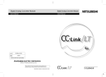
COMPLIANCE WITH THE EMC, LOW VOLTAGE, AND MACHINERY DIRECTIVES
To configure a system meeting the requirements of the EMC, Low Voltage,
and Machinery Directives when incorporating the Mitsubishi programmable
controller (EMC, Low Voltage, and Machinery Directives compliant) into
other machinery or equipment, refer to the userAfs manual for the CPU
module used.
The CE mark, indicating compliance with the EMC, Low Voltage,
and Machinery Directives, is printed on the rating plate of the
programmable controller.
A - 12
ABOUT THE GENERIC TERMS AND ABBREVIATIONS
This manual uses the following generic terms and abbreviations to describe
the QS0J61BT12 CC-Link Safety system master module, unless otherwise
specified.
Generic Term/
Description
Abbreviation
PLC
Safety PLC
Standard PLC
Abbreviation for Programmable Controller.
General name for safety CPU module, safety power supply module, safety main base unit,
CC-Link safety master module and CC-Link safety remote I/O module.
General name of each module for MELSEC-Q series, MELSEC-QnA series, MELSEC-A series
and MELSEC-FX series. (Used for distinction from safety PLC.)
QS0J61BT12
Abbreviation for QS0J61BT12 CC-Link Safety System Master Module
Safety master module
Other name for QS0J61BT12.
Standard master module
General name for CC-Link system master modules
Safety CPU module
Abbreviation for QS001CPU type safety CPU module.
Cyclic transmission
Safety master station
Safety remote I/O station
Transmission method to periodically communicate the contents of remote I/O and remote
registers.
Station which controls the CC-Link Safety system.
One station is required per system.
Remote station which handles only the informaion in bit units.
Compatible with the safety communications.
Standard remote I/O
Remote station which handles only the information in bit units.
station
Not compatible with the safety communications.
Remote I/O station
Remote device station
Safety remote station
Standard remote station
Remote station
Slave station
General name for safety remote I/O station and standard remote I/O station
Remote station which handles information in both bit and word units.
Not compatible with the safety communications.
Other name for safety remote I/O station
General name for standard remote I/O station and remote device station
General name for safety remote I/O station, standard remote I/O station and remote device
station. They are controlled by the safety master station.
General name for safety remote I/O station, standard remote I/O station and remote device
station
Link special relay (for CC-Link safety system)
SB
Bit information that indicates the module operating status and data link status of the master
station. (Expressed as SB for convenience)
Link special register (for CC-Link safety system)
SW
16-bit information that indicates the module operating status and data link status of the master
station. (Expressed as SW for convenience)
Remote input (for CC-Link safety system)
RX
Information entered in bit units from the remote station to the master station. (Expressed as RX
for convenience)
Remote output (for CC-Link safety system)
RY
Information output in bit units from the master station to the remote station. (Expressed as RY for
convenience)
Remote register (Write area for CC-Link safety system)
RWw
Information output in 16-bit units from the master station to the remote device station.
(Expressed as RWw for convenience)
A - 13
Generic Term/
Description
Abbreviation
Remote register (Read area for CC-Link safety system)
RWr
Information entered in 16-bit units from the remote device station to the master station.
(Expressed as RWr for convenience)
GX Developer
A - 14
General product name for the models, SW8D5C-GPPW, SW8D5C-GPPW-A,
SW8D5C-GPPW-V and SW8D5C-GPPW-VA.
PRODUCT COMPONENTS
The components of the QS0J61BT12 are listed below.
Item name
QS0J61BT12 main unit
Terminating resistor 110
Quantity
1
, 1/2 W (brown-brown-brown)
(used when wiring with the Version 1.10 compatible CC-Link dedicated cable or CC-Link
2
dedicated cable)
A - 15
Memo
A - 16
1
OVERVIEW
1
CC-Link Safety system
master module
Model
QS0J61BT12
QS0J61BT12-K
Description
A module which is mounted on a safety main base
unit and establishes connection to CC-Link Safety
An S-mark*1 certified CC-Link Safety system
3
master module
1.1 Overview
4
FUNCTIONS
The CC-Link Safety system is a network system for which the communication error
detection function of the CC-Link system has been enhanced, and thus it can be applied to
the cases where safety is required in machine controls.
SPECIFICATIONS
Product Name
2
SYSTEM
CONFIGURATION
This manual describes the specifications, part names and settings of the QS0J61BT12
CC-Link Safety system master module (hereinafter referred to as the QS0J61BT12) which
is used with the MELSEC-QS series programmable controller CPUs.
When applying the following program examples to the actual system, make sure to
examine the applicability and confirm that it will not cause system control problems.
OVERVIEW
CHAPTER1 OVERVIEW
DATA LINK PROCESSING
TIME AND STATION STATUS
AT ERROR OCCURRENCE
5
PARAMETER SETTINGS
6
PROCEDURE BEFORE
STARTING THE DATA
LINK
7
PROGRAMMING
SPECIFICATIONS
8
1.1 Overview
1-1
1
OVERVIEW
1.2 Compatibility with CC-Link
This product supports the following CC-Link functions and performance.
Cyclic transmission
Less restrictions on the station-to-station cable length
CC-Link Safety
1.3 Features
The CC-Link Safety system and the QS0J61BT12 feature the following.
(1) Safety network system of the highest level
The CC-Link Safety system is a safety network system which has obtained the
highest safety level (EN954-1 Category 4, ISO13849-1 PL e, IEC61508 SIL3)
applicable to programmable controllers. This allows easy construction of safety
network system with high safety.
(2) Communication possible in a network comprising safety remote stations and
standard remote stations
Safety remote stations and standard remote stations can be installed together on the
same network. Safety I/O devices such as emergency stop buttons, light curtains and
safety relays can be installed together with standard I/O devices such as start buttons,
reset buttons and indicators on the same network.
(3) Safety remote station parameter setting function
With GX Developer, safety remote station parameters can be set easily.
(4) Identifying the communication target station (remote I/O station)
By presetting the model name and production information of a safety remote station in
network parameter setting, safety remote stations different from the setting can be
detected when connected.
(5) Error history registration function
Error information received from safety remote stations and the one occurred during
communication with safety remote stations are registered to the error history in the
safety CPU.
Use GX Developer to read such error history information, making troubleshooting
easy for the CC-Link Safety system and safety remote stations.
1-2
1.2 Compatibility with CC-Link
2
SYSTEM CONFIGURATION
1
OVERVIEW
CHAPTER2 SYSTEM CONFIGURATION
The system configuration for the CC-Link Safety system is described below.
Up to 64 stations in total of safety remote I/O stations, standard remote I/O stations and
remote device stations can be connected to a single safety master station.
However, the following conditions must all be satisfied.
3
a: Number of modules occupying 1 station
Condition 1
{(1 a)+{(2 b)+{(3 c)+{(4 d)}=64
b: Number of modules occupying 2 stations
c: Number of modules occupying 3 stations
A
B+C
64
SPECIFICATIONS
d: Number of modules occupying 4 stations
A: Number of standard remote I/O stations
B: Number of remote device stations
42
{(16 A)+{(54 (B+C))}
2304
C: Number of safety remote I/O stations
4
FUNCTIONS
Power supply/CPU/CC-Link Safety master module
CC-Link Safety remote I/O station
DATA LINK PROCESSING
TIME AND STATION STATUS
AT ERROR OCCURRENCE
5
CC-Link Safety
GX Developer
(Version 8.40S or later)*1
Standard Remote device station
Standard remote I/O station
CC-Link Safety
remote I/O station
6
Light curtain
PARAMETER SETTINGS
Emergency stop switch
CC-Link Safety
remote I/O station
Emergency stop switch
PROCEDURE BEFORE
STARTING THE DATA
LINK
7
Safety relay
* 1 : The available functions vary depending on the version. For details, refer to the following manual.
8
QSCPU User's Manual(Function Explanation,Program Fundamentals)
PROGRAMMING
SPECIFICATIONS
Condition 2
SYSTEM
CONFIGURATION
2
2.1 System Configuration
2.1 System Configuration
2-1
2
SYSTEM CONFIGURATION
2.2 Applicable System
This section explains applicable PLC CPU models and the number of mountable modules.
2.2.1 Applicable modules and number of mountable modules
(1) Applicable modules and number of mountable modules
The CPU module for which the QS0J61BT12 can be mounted and its mountable
number are listed in the table below.
Number of mountable
Applicable module
Safety CPU
module
Remark
modules
QS001CPU
Up to 2
(2) Applicable base unit
The QS0J61BT12 can be mounted in any I/O slot of a safety main base unit.
Product name
Model name
Safety main base unit
QS034B
Remarks
(3) Applicable software package
The software package available for the QS0J61BT12 is listed below:
Product name
Model name
GX Developer
SWnD5C-GPPW*1
Remarks
Required MELSEC PLC programming
software.
"n" in the model name is 8 or greater.
* 1 Product in version 8.40S or later is required.
(4) Usable slave stations
Slave station types supported by the QS0J61BT12 are listed below.
:Connectable
Remote station type
Safety
Remote I/O station
Remote device station
Standard
Intelligent device station
Local station
Standby master station
2-2
:Not connectable
Remote I/O station
2.2 Applicable System
2.2.1 Applicable modules and number of mountable modules
Ver.1-compatible
Ver.1-compatible
Ver.2-compatible
Ver.1-compatible
Ver.2-compatible
Ver.1-compatible
Ver.2-compatible
Ver.1-compatible
Ver.2-compatible
SYSTEM CONFIGURATION
1
OVERVIEW
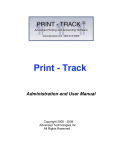
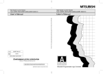
2.2.2 How to check the function version
The following shows how to check the function version.
(1) How to check the function version of the QS0J61BT12
2
CC-Link Safety MASTER UNIT PASSED
MODEL QS0J61BT12
SYSTEM
CONFIGURATION
(a) Checking the "SERIAL" of the rating plate on the module side
3
Serial No. (first 5 digits)
SPECIFICATIONS
Function version
SERIAL 080910000000000 - A
Standard symbol for
conformance is described.
4
MADE IN JAPAN
FUNCTIONS
(b) See Section 9.4 for how to check the function version with GX Developer.
2.2.3 Module Replacement
5
Module
Replacement Cycle
CC-Link Safety system master module
10 years
DATA LINK PROCESSING
TIME AND STATION STATUS
AT ERROR OCCURRENCE
Replace the module according to the following replacement cycle.
PARAMETER SETTINGS
6
PROCEDURE BEFORE
STARTING THE DATA
LINK
7
8
PROGRAMMING
SPECIFICATIONS
2
2.2 Applicable System
2.2.2 How to check the function version
2-3
3
SPECIFICATIONS
CHAPTER3 SPECIFICATIONS
This section describes the specifications of the QS0J61BT12.
3.1 Performance Specifications
Table3.1 shows the performance specifications of the QS0J61BT12.
Refer to the User’s Manual of the CPU for the general specifications of the QS0J61BT12.
Table3.1 Performance Specifications
Item
Specifications
Transmission rate
Select from 156kbps/625kbps/2.5Mbps/5Mbps/10Mbps
Maximum overall cable distance
Differs according to transmission rate (Refer to Section 3.1.1)
(Maximum transmission distance)
Maximum No. of connectable modules
64 modules
Remote I/O (RX, RY): 2048 points
Maximum No. of link points per system
Remote register (RWr): 256 points (remote device station
Remote register (RWw): 256 points (master station
Station
type
Safety remote station
master station)
remote device station)
Standard remote station
Number
of
Link points per remote station
1 station
1 station
2 stations
3 stations
4 stations
RX
32 points
32 points
64 points
96 points
128 points
128 points
occupied
stations
RY
32 points
32 points
64 points
96 points
RWr
0 points
4 points
8 points
12 points
16 points
RWw
0 points
4 points
8 points
12 points
16 points
Communication method
Broadcast polling method
Synchronization method
Flag synchronous system
Coding method
NRZI method
Transmission path
Bus (RS-485)
Transmission format
HDLC compliant
CRC32 *2
(X32+X26+X23+X22+X16+X12+X11+X10+X8+X7+X5+X4+X2+X+1)
Error control system
CRC16
(X16+X12+X5+1)
Recommended connection cable
No. of I/O occupied points
Version 1.10 compatible CC-Link dedicated cable *1
32 points (I/O assignment: 32 intelligent points)
5V DC internal current consumption
0.46A
Weight
0.12kg
*1
CC-Link dedicated cable (Ver.1.00) or CC-Link dedicated high-performance cable can be also
used. Using a cable together with another type of cable is not allowed. Attach terminating
resistors which match the cable type.(Refer to Section 7.6)
* 2 Error detection using CRC32 is not performed for communication with standard remote I/O
stations or remote device stations.
3-1
3.1 Performance Specifications
SPECIFICATIONS
1
OVERVIEW
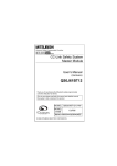
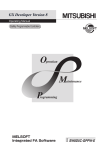
3.1.1 Maximum overall cable distance (for Ver. 1.10)
The relation of the transmission speed and maximum overall cable distance when
configuring the entire system with Version 1.10 modules and cable is shown below.
Remote I/O station
or remote
device station
Remote I/O station
or remote
device station
Remote I/O station
or remote
device station
Station to station
cable length
3
Maximum overall cable distance
Version 1.10 compatible CC-Link dedicated cable (terminating resistor of 110W used)
625kbps
2.5Mbps
Station to station cable length
Maximum overall cable distance
1200m
20cm or longer
5Mbps
10Mbps
900m
400m
4
160m
100m
FUNCTIONS
Transmisson Speed
156kbps
SPECIFICATIONS
Remote I/O station
or remote
device station
3.1.2 Maximum overall cable distance (for Ver. 1.00)
For the relation between the transmission rate and the maximum overall cable distance,
refer to the following:
CC-Link Partner Association website: http://www.cc-link.org/
5
DATA LINK PROCESSING
TIME AND STATION STATUS
AT ERROR OCCURRENCE
Master Station
SYSTEM
CONFIGURATION
2
PARAMETER SETTINGS
6
PROCEDURE BEFORE
STARTING THE DATA
LINK
7
8
PROGRAMMING
SPECIFICATIONS
3
3.1 Performance Specifications
3.1.1 Maximum overall cable distance (for Ver. 1.10)
3-2
3
SPECIFICATIONS
3.2 CC-Link Dedicated Cable
Use CC-Link dedicated cables in the CC-Link Safety systems.
Performance of the CC-Link Safety system cannot be guaranteed if any cables other than
CC-Link dedicated cables are used.
For the specifications and any inquiries on the CC-Link dedicated cables, refer to the
following:
CC-Link Partner Association website: http://www.cc-link.org/
Remark
For details, refer to the CC-Link Cable Wiring Manual issued by the CC-Link
Partner Association.
3-3
3.2 CC-Link Dedicated Cable
3.1.2 Maximum overall cable distance (for Ver. 1.00)
4
FUNCTIONS
1
OVERVIEW
CHAPTER4 FUNCTIONS
This chapter explains the functions of the QS0J61BT12.
Table4.1 below lists the functions.
Table4.1 Function list (1/2)
Reference
section
stations.
Exchanges ON/OFF information and numerical data across a
composed of safety and standard
network composed of both safety remote stations and standard
remote stations
remote stations.
Refreshes devices (RX/RY/RWr/RWw) on CC-Link Safety to/from
Automatic refresh function
any devices on the safety CPU, based on the setting in GX
Developer.
Identifying the communication target
Identifies the safety remote station connected, judging whether or
station (remote I/O station)
not it is the correct one.
Station number overlap checking
function
Section
4.2.2
Section
Checks for overlapping in number of occupied stations of remote
stations, and whether more than one master station (station No.
0) exist in the system or not.
because of power off, and continues the data link among normal
modules only.
When a module, which has been disconnected from the data link
Section
Section
4.2.5
Section
4.2.6
Section
Automatic return function
because of power off, returns to the normal status, it automatically
Data link stop function at safety CPU
joins the data link.
Stops the data link when a stop error occurred on the safety CPU
error
module.
Clearing inputs from data link faulty
Clears input (received) data from a station where a data link error
stations
occurred due to power-off, etc.
Slave station forced clear function at
Forcibly clears output data to slave stations when the safety CPU
Section
safety CPU stop
stops.
Transfers error information that is generated on safety remote
4.2.10
Error history registration function
stations and CC-Link Safety to the safety CPU, and registers the
Section
Section
4.2.9
By assigning modules that will be connected in the future as
reserved stations, they will not be treated as data link faulty
stations.
Section
4.2.11
Section
4.2.12
5
6
7
8
PROGRAMMING
SPECIFICATIONS
Reserved station function
4.2.7
4.2.8
information as error history.
4
4.2.3
4.2.4
Disconnects the module that cannot continue the data link
Slave station cut-off function
4.2.1
SPECIFICATIONS
O stations
Communication across a network
3
Section
FUNCTIONS
Performs on/off data communication with safety remote I/O
DATA LINK PROCESSING
TIME AND STATION STATUS
AT ERROR OCCURRENCE
Communication with safety remote I/
PARAMETER SETTINGS
Description
PROCEDURE BEFORE
STARTING THE DATA
LINK
Item
SYSTEM
CONFIGURATION
2
4.1 Function List
4.1 Function List
4-1
4
FUNCTIONS
Table 4.1 Function list (2/2)
Item
Description
Reference
section
Synchronous mode: Performs link scan in synchronization with
Scan synchronization function
sequence scan.
Section
Asynchronous mode: Performs link scan not in synchronization
4.2.13
with sequence scan.
When a communication error occurs between a safety master
Safety remote station interlock
station and a safety remote station, this function prevents
Section
function
automatic restart of input and output from the relevant safety
4.2.14
remote station(s).
4-2
4.1 Function List
FUNCTIONS
1
OVERVIEW
4.2 Detailed Explanation of Functions
This section provides detailed explanation on the functions of the QS0J61BT12.
4.2.1 Communication with safety remote I/O stations
The QS0J61BT12 exchanges ON/OFF data of safety components (e.g. emergency stop
buttons, light curtains) and safety relays connected to safety remote I/O stations using its
remote input (RX) and remote output (RY).
Remote stations can be connected in any order, and their station number can also be set
in any order.
Safety master module
(1)
Network parameters
Safety remote I/O station
Network
parameters
(2)
(2)
Safety remote station
parameters
Safety remote
station parameters
3
Initial setting
Safety remote
station parameters
SPECIFICATIONS
Safety CPU module
SYSTEM
CONFIGURATION
2
4
FUNCTIONS
Automatic refresh
parameters
Buffer memory
Automatic refresh
Y
Automatic refresh
(3)
Remote input
RX
Link scan
Remote output
RY
Link scan
5
Input
DATA LINK PROCESSING
TIME AND STATION STATUS
AT ERROR OCCURRENCE
(4)
X
(6)
(5)
Output
(1) After the safety PLC system is powered on, network parameters in the safety
CPU module are transferred to the safety master module, and then a data link is
started up.
(2) The safety master module sends "safety remote station parameters", which are
stored in the safety CPU module, to the linked safety remote I/O stations. The
safety remote I/O stations start I/O operations upon reception of the "safety
remote station parameters".
7
PROCEDURE BEFORE
STARTING THE DATA
LINK
[Data link startup]
PARAMETER SETTINGS
6
8
PROGRAMMING
SPECIFICATIONS
4
4.2 Detailed Explanation of Functions
4.2.1 Communication with safety remote I/O stations
4-3
4
FUNCTIONS
[Remote input]
(3) The safety master module reads input status data of safety remote I/O stations,
and saves them in its remote input (RX) area.
(4) The safety CPU module saves the remote input (RX) data of the safety master
module to the CPU device that is specified with the auto refresh parameter.
This is performed in the END processing of the sequence scan.
Safety CPU module
Safety master module
X400
RX0F to RX00
(4)
to
(3)
Safety remote I/O station
(Station number 2,
1 occupied station)
X0F to X00
RX1F to RX10
RX2F to RX20
X43F
Safety remote I/O station
(Station number 1,
1 occupied station)
X0F to X00
(3)
RX3F to RX30
X1F to X10
RX4F to RX40
to
RX7FF to RX7F0
16-point module
4-4
4.2 Detailed Explanation of Functions
4.2.1 Communication with safety remote I/O stations
32-point module
4
FUNCTIONS
1
(6) The safety master module sends the remote output (RY) values to safety
remote I/O stations.
Safety CPU module
Safety remote I/O station Safety remote I/O station
(station No.3, 1
(station No.4, 1
occupied station)
occupied station)
Safety master module
RY0F to RY00
2
SYSTEM
CONFIGURATION
(5) The safety CPU module saves the CPU device value set by the auto refresh
parameter into the remote output (RY) area of the safety master module. This is
performed in the END processing of the sequence scan.
OVERVIEW
[Remote output]
3
RY1F to RY10
SPECIFICATIONS
RY2F to RY20
RY3F to RY30
Y440
RY6F to RY60
Y47F
(6)
Y0F to Y00
RY5F to RY50
Y0F to Y00
(6)
RY7F to RY70
4
Y1F to Y10
FUNCTIONS
RY8F to RY80
to
RY7FF to RY7F0
16-point module
32-point module
5
POINT
In remote registers RWw and RWr of safety remote I/O stations, the system uses
4 words per station. The automatic refresh setting is not necessary for them.
DATA LINK PROCESSING
TIME AND STATION STATUS
AT ERROR OCCURRENCE
to
RY4F to RY40
(5)
PARAMETER SETTINGS
6
PROCEDURE BEFORE
STARTING THE DATA
LINK
7
PROGRAMMING
SPECIFICATIONS
8
4.2 Detailed Explanation of Functions
4.2.1 Communication with safety remote I/O stations
4-5
4
FUNCTIONS
4.2.2 Communication across a network composed of safety remote stations
and standard remote stations
The following is a simplified figure showing how communication is performed when safety
remote stations and standard remote stations are connected on the same network.
When these remote stations are connected together on the same network, there are no
restrictions on the order of connections and station numbers.
POINT
Before creating a program for a network where both safety remote stations and
standard remote stations are installed, refer to the programming precautions
explained in Safety Application Guide.
Safety master station
Safety remote I/O station
Remote device station
Standard remote I/O station
Safety master station
Safety remote I/O station
(Station No.1, 1
occupied station)
RX
RX
Station No.1
Station No.1
Station No.2
Standard remote I/O station
(Station No.2, 1
occupied station)
RX
Station No.2
Station No.3
RX
Station No.3
Station No.4
Station No.4
RY
RY
Station No.1
Station No.1
Station No.2
Remote device station
(Station No.3, 2
occupied stations)
RY
Station No.2
RY
Station No.3
Station No.3
Station No.4
Station No.4
RWr
Station No.1
Station No.2
RWr
Station No.3
Station No.3
Station No.4
Station No.4
RWw
Station No.1
Station No.2
4-6
RWw
Station No.3
Station No.3
Station No.4
Station No.4
4.2 Detailed Explanation of Functions
4.2.2 Communication across a network composed of safety remote
FUNCTIONS
1
Data in remote input (RX) and remote register (RWr) areas of remote stations are
stored into the safety master station.
Remote input (RX)
Remote input (RX)
RX0F to RX00
X0F to X00
RX1F to RX10
X1F to X10
Standard remote I/O station
(Station No.2, 1
occupied station)
Remote device station
(Station No.3, 2
occupied stations)
2
SYSTEM
CONFIGURATION
Safety master station
Safety remote I/O station
(Station No.1, 1
occupied station)
Remote input (RX)
RX2F to RX20
X0F to X00
RX3F to RX30
X1F to X10
RX4F to RX40
Remote input (RX)
RX0F to RX00
RX5F to RX50
RX1F to RX10
OVERVIEW
[Remote input, Remote register (RWr)]
3
RX6F to RX60
SPECIFICATIONS
RX7F to RX70
to
RX7FF to RX7F0
Remote register (RWr)
*1
Used by the
system
4
RWr4
RWr5
Remote register (RWr)
RWr8
RWr0
RWr9
RWr1
RWrA
RWr2
RWrB
RWr3
RWrC
RWr4
RWrD
RWr5
RWrE
RWr6
RWrF
RWr7
5
DATA LINK PROCESSING
TIME AND STATION STATUS
AT ERROR OCCURRENCE
RWr7
FUNCTIONS
RWr6
to
RWrFF
PARAMETER SETTINGS
6
* 1 On a safety remote I/O station, 4 points of RWr are used by the system.
PROCEDURE BEFORE
STARTING THE DATA
LINK
7
8
PROGRAMMING
SPECIFICATIONS
4
4.2 Detailed Explanation of Functions
4.2.2 Communication across a network composed of safety remote
4-7
4
FUNCTIONS
[Remote output, Remote register (RWw)]
Data in remote output (RY) and remote register (RWw) areas of the safety master
station are sent to respective remote stations.
Safety master station
Remote output (RY)
RY0F to RY00
RY1F to RY10
RY2F to RY20
RY3F to RY30
Safety remote I/O station Standard remote I/O station
(Station No.2, 1
(Station No.1, 1
occupied station)
occupied station)
Remote device station
(Station No.3, 2
occupied stations)
Remote output (RY)
Y0F to Y00
Y1F to Y10
Remote output (RY)
Y0F to Y00
Y1F to Y10
RY4F to RY40
Remote output (RY)
RY0F to RY00
RY5F to RY50
RY1F to RY10
RY6F to RY60
RY7F to RY70
to
RY7FF to RY7F0
Remote register (RWw)
Used by the
system
*1
RWw4
RWw5
RWw6
RWw7
Remote register (RWw)
RWw8
RWw0
RWw9
RWw1
RWwA
RWw2
RWwB
RWw3
RWwC
RWw4
RWwD
RWw5
RWwE
RWw6
RWwF
RWw7
to
RWwFF
* 1 On a safety remote I/O station, 4 points of RWw are used by the system.
4-8
4.2 Detailed Explanation of Functions
4.2.2 Communication across a network composed of safety remote
FUNCTIONS
1
(1) Settable devices
Devices settable for the auto refresh function are as follows:
Buffer memory
X
Remote input (RX)
Y
–
Bit device
M
B
: Settable, –: Not settable
F
SB
–
–
–
–
Remote output (RY)
–
Remote register (RWr)
–
–
–
–
Remote register (RWw)
–
–
–
–
Link special relay (SB)
–
–
–
–
–
–
–
SW
–
–
–
–
–
–
–
–
–
–
–
–
–
–
4
FUNCTIONS
–
–
DATA LINK PROCESSING
TIME AND STATION STATUS
AT ERROR OCCURRENCE
5
6
PARAMETER SETTINGS
(SW)
–
3
7
PROCEDURE BEFORE
STARTING THE DATA
LINK
Link special register
D
Word device
W
T
ST C
SPECIFICATIONS
Table4.2 Devices settable for auto refresh
2
SYSTEM
CONFIGURATION
With this function, data in the following devices are refreshed all together to the devices of
the safety CPU module when it executes END processing: remote input (RX), remote
output (RY) and remote registers (RWr, RWw) of remote stations, and link special relay
(SB) and like special register (SW) of the safety master module.
OVERVIEW
4.2.3 Auto refresh function
8
PROGRAMMING
SPECIFICATIONS
4
4.2 Detailed Explanation of Functions
4.2.3 Auto refresh function
4-9
4
FUNCTIONS
(2) Operation in auto refresh
When the auto refresh parameters are set, the relation between the CPU devices and
the refresh-target devices (remote input (RX), remote output (RY), remote registers
(RWr, RWw), link special relay (SB) and like special register (SW)) is as shown on the
system configuration example below.
Safety CPU module
Allocate as
follows:
RX to X400
RY to Y400
RWw to W0
RWr to W100
SB to SB0000
SW to SW0000
Safety master module
Remote device station
Safety remote I/O station
Station No.1
1 occupied station
Remote
device station
Station No.2
2 occupied stations
Station No.5
2 occupied stations
Standard remote
I/O station
Station No.4
1 occupied station
The relation between the CPU devices and the devices of each remote station is as
shown below. Note that this figure is illustrated based on the following setting: remote
input (RX) is set to X400, remote output (RY) is set to Y400, remote registers (RWr,
RWw) are set to W0 and W100 respectively, link special relay (SB) is set to SB0000
and link special register (SW) is set to SW0000.
Station No.1
Station No.2
Station No.4
Station No.5
Station No.1
Station No.2
Station No.4
Station No.5
Station No.1
Station No.2
Station No.4
Station No.5
Station No.1
Station No.2
Station No.4
Station No.5
Safety CPU module
Safety master module
Safety remote I/O station
(Station No.1, 1
occupied station)
X41F to X400
RX1F to RX00
X1F to X00
X43F to X420
RX3F to RX20
RX1F to RX00
X45F to X440
RX5F to RX40
RX3F to RX20
X47F to X460
RX7F to RX60
X49F to X480
RX9F to RX80
RX1F to RX00
X4BF to X4A0
RXBF to RXA0
RX3F to RX20
W3 to W0
Used by the system
Remote device station
(Station No.2, 2
occupied stations)
Remote device station
(Station No.5, 2
occupied stations)
X1F to X00
Used by the system
W7 to W4
RWr7 to RWr4
RWr3 to RWr0
WB to W8
RWrB to RWr8
RWr7 to RWr4
WF to WC
RWrF to RWrC
W13 to W10
RWr13 to RWr10
RWr3 to RWr0
W17 to W14
RWr17 to RWr14
RWr7 to RWr4
Y41F to Y400
RY1F to RY00
Y43F to Y420
RY3F to RY20
RY1F to RY00
Y45F to Y440
RY5F to RY40
RY3F to RY20
Y47F to Y460
RY7F to RY60
Y49F to Y480
RY9F to RY80
RY1F to RY00
Y4BF to Y4A0
RYBF to RYA0
RY3F to RY20
W103 to W100 *1
Used by the system
W107 to W104
RWw7 to RWw4
RWw3 to RWw0
W10B to W108
RWw13 to RWw8
RWw7 to RWw4
Y1F to Y00
Y1F to Y00
Used by the system
W10F to W10C
RWwF to RWwC
W113 to W110
RWw13 to RWw10
RWw3 to RWw0
W117 to W114
RWw17 to RWw14
RWw7 to RWw4
SB1FF to SB0
SB1FF to SB0
SW1FF to SW0
SW1FF to SW0
*1: The CPU devices assigned to RWw of safety remote I/O stations are not refreshed automatically.
4 - 10
Standard remote I/O station
(Station No.4, 1
occupied station)
4.2 Detailed Explanation of Functions
4.2.3 Auto refresh function
4
FUNCTIONS
1
1) On each of safety remote I/O stations, 4 words in the remote register (RWr,
RWw) areas are used by the system.
2) When the automatic refresh setting is not made for remote input (RX), remote
output (RY), remote register (RWr, RWw), link special relay (SB), and link
special register (SW), the resulting operation is shown in "Table4.3 When the
automatic refresh setting is not made".
from
remote station
sequence
program
Read/write
from GX
Developer
Remote input (RX)
–
–
Remote output (RY)
0*1
0*2
Remote register (RWr)
–
Remote register (RWw)
0*1
Link special relay (SB)
Link special register
–
allowed
–
*3
Read/write
allowed
–
0*2
–
Read/write not
allowed
*3
Read/write
allowed
–
5
DATA LINK PROCESSING
TIME AND STATION STATUS
AT ERROR OCCURRENCE
* 1: Forced output to slave stations using GX Developer is also not allowed.
* 2: Forced output to slave stations using GX Developer is allowed.
* 3: To read or write data from the sequence program, perform the automatic refresh setting.
[Setting method]
For the specification of automatic refresh parameters, refer to CHAPTER 6
PARAMETER SETTINGS
6
PROCEDURE BEFORE
STARTING THE DATA
LINK
7
8
PROGRAMMING
SPECIFICATIONS
(SW)
Read/write not
4
FUNCTIONS
Data output to
Standard remote station
Read/write
Read/write
Data output to
from
from GX
remote station
sequence
Developer
program
SPECIFICATIONS
3
Table4.3 When the automatic refresh setting is not made
Safety remote station
Read/write
2
SYSTEM
CONFIGURATION
The following are precautions for setting the automatic refresh parameters.
OVERVIEW
(3) Precautions for setting the automatic refresh parameters
4.2 Detailed Explanation of Functions
4.2.3 Auto refresh function
4 - 11
4
FUNCTIONS
4.2.4 Identifying the communication target station (remote I/O station)
This function determines whether a safety remote station is properly connected or not.
Standard remote stations are not identified by this function.
The following shows the identification methods of the safety master station and the ranges
allowable for respective methods.
(1) Identification by link ID
(2) Identification by product model name
(3) Identification by module technical version
(4) Identification by production information
Safety master station Safety master station
with link ID 1
with link ID 3
(1) Identifies the station having
the same link ID.
4 - 12
(2) Identifies the station having
the same model name
(3) Identifies the station having
the same module technical
version.
(4) Identifies the station having
the production information
matched.
4.2 Detailed Explanation of Functions
4.2.4 Identifying the communication target station (remote I/O station)
FUNCTIONS
1
Safety master station
with link ID 1
Safety master station
with link ID 3
Safety remote station
with link ID 3
2
SYSTEM
CONFIGURATION
Whether the link ID set in a safety master station matches the one set in a safety
remote station or not is determined.
By using this function, a mistake in connection with the master station can be found.
When these link IDs do not match, CC-LINK RECEIVED DATA ERROR (Error code
8332) is saved in the error history of the safety CPU module on the safety master
station.
OVERVIEW
(1) Identifying a safety remote station by link ID
3
SPECIFICATIONS
Mismatch in link ID
4
FUNCTIONS
The connection is
wrong.
Safety remote station
with link ID 1
DATA LINK PROCESSING
TIME AND STATION STATUS
AT ERROR OCCURRENCE
5
PARAMETER SETTINGS
6
PROCEDURE BEFORE
STARTING THE DATA
LINK
7
8
PROGRAMMING
SPECIFICATIONS
4
4.2 Detailed Explanation of Functions
4.2.4 Identifying the communication target station (remote I/O station)
4 - 13
4
FUNCTIONS
(2) Identifying a safety remote station by product model name
Whether the name of the model mounted on a safety remote station matches the one
set with a network parameter or not is determined.
If they do not match, CC-LINK PRODUCT INFO. MISMATCH (Error code 8310) is
saved in the error history of the safety CPU module.
Network parameter setting
Station No.1
Safety remote I/O station
Product model name "ZZZZZZ"
Station No.1
Safety remote I/O station
Product model name "XXXXXX"
Mismatch in product
model name
4 - 14
4.2 Detailed Explanation of Functions
4.2.4 Identifying the communication target station (remote I/O station)
FUNCTIONS
1
Network parameter setting
Station No.1
Safety remote I/O station
Module technical version "A"
2
SYSTEM
CONFIGURATION
Whether the module technical version of the model mounted on a safety remote
station matches the one selected for the network parameter or not is determined.
If they do not match, CC-LINK PRODUCT INFO. MISMATCH (Error code 8310) is
saved in the error history of the safety CPU module.
OVERVIEW
(3) Identifying a safety remote station by module technical version
Station No.1
Safety remote I/O station
Module technical version "B"
SPECIFICATIONS
3
Mismatch in
module technical
versions
FUNCTIONS
4
DATA LINK PROCESSING
TIME AND STATION STATUS
AT ERROR OCCURRENCE
5
PARAMETER SETTINGS
6
PROCEDURE BEFORE
STARTING THE DATA
LINK
7
8
PROGRAMMING
SPECIFICATIONS
4
4.2 Detailed Explanation of Functions
4.2.4 Identifying the communication target station (remote I/O station)
4 - 15
4
FUNCTIONS
(4) Identifying a safety remote station by production information
When product information has been specified in the network parameter setting,
whether it matches the actual one or not is determined.
If the product information set in the network parameter setting does not match that of
the actual safety remote station, CC-LINK PRODUCT INFO. MISMATCH (Error code
8310) is saved in the error history of the safety CPU module.
Network parameter setting
Station No.1
Safety remote I/O station
Product model name "ZZZZZZ"
Production information 123
Station No.1
Safety remote I/O station
Product model name "ZZZZZZ"
Production information 125
Mismatch in
production
information
[Setting method]
For the specification of link ID, product model name, module technical version, or
product information, refer to CHAPTER 6.
4 - 16
4.2 Detailed Explanation of Functions
4.2.4 Identifying the communication target station (remote I/O station)
FUNCTIONS
1
This function checks the status of the remote stations connected to the safety master
station to check if there is duplication in occupied station numbers and if more than one
station have station number 0 in the system.
OVERVIEW
4.2.5 Station number overlap checking function
2
When the PLC is powered OFF and then ON or when data link is started due to reset
cancellation of the safety CPU module, this function checks remote stations for any
duplication in occupied station numbers.
3
(Example) There is duplication in occupied station numbers.
SPECIFICATIONS
Station
number 2
2) Even if an overlap exists, the safety master station continues the data link with
the remaining normally functioning stations.
3) Correct the station number setting of the remote station and reset the PLC
CPU on the safety master station. Doing so will turn off the "ERR." LED on the
safety master module, clearing the data stored in SW0098 to SW009B.
(2) Checking for duplication of station number 0
When the PLC is powered OFF and then ON or when data link is started due to reset
cancellation of the safety CPU module, this function checks if any other master station
(station number set to 0) exists on the same network and is performing
communication.
1) When duplication is detected, the "ERR." LED on the safety master module
turns ON, and an error code is stored to SW006A (switch setting status),
turning ON SB006A (switch setting status).
2) Reducing the safety master stations to one and resetting its PLC CPU will turn
off the "ERR." LED and clear the data of SW006A.
5
DATA LINK PROCESSING
TIME AND STATION STATUS
AT ERROR OCCURRENCE
1) When duplication is detected, the "ERR." LED on the safety master module
flashes, and the status of the detected duplication is stored to SW0098 to
SW009B (station No. duplication status).
FUNCTIONS
4
Overlap
6
PARAMETER SETTINGS
Safety remote I/O station (station number 2,
number of occupied stations: 1)
Station
Station
number 1 number 2
7
PROCEDURE BEFORE
STARTING THE DATA
LINK
Remote device station (station number 1,
number of occupied stations: 2)
SYSTEM
CONFIGURATION
(1) Checking for occupied station number overlap
8
PROGRAMMING
SPECIFICATIONS
4
4.2 Detailed Explanation of Functions
4.2.5 Station number overlap checking function
4 - 17
4
FUNCTIONS
4.2.6 Slave station cut-off function
When a remote station becomes incapable of continuing data link due to a reason such as
power-off or a safety monitoring timeout error, this function disconnects that remote station
only, allowing the other normal stations to continue the data link.
Safety
master
station
Down
Remote
station
Remote
station
Terminating
resistor
Terminating
resistor
Continues data link excluding faulty stations.
[About the safety monitoring timeout error]
If no signal has been normally received from a safety remote station for the period of
the safety refresh monitoring time or longer, a safety monitoring timeout error is
detected. If this occurs, the safety master station disconnects only the relevant
safety remote station, and CC-LINK DATA RECEPTION TIMEOUT (Error code 8320
to 8329) is stored in the error history of the safety CPU module.
Safety refresh monitoring time
Normal reception
Safety master station
Safety remote station
4 - 18
4.2 Detailed Explanation of Functions
4.2.6 Slave station cut-off function
Start
Measuring time
Stop
Normal reception
Start
Measuring time
Stop
Start
Safety refresh
monitoring timer
Safety monitoring
timeout error
occurred.
Measuring time
Data error
Data error
Safety master station
stops data link with
the target station.
FUNCTIONS
1
Safety
master
station
Remote
station
2
SYSTEM
CONFIGURATION
In the event of cable disconnection, the data link cannot be performed because
there is no terminating resistor. (The "ERR." LED on the safety master module
turns ON.)
OVERVIEW
POINT
Remote
station
3
Terminating
resistor
SPECIFICATIONS
Disconnection
FUNCTIONS
4
DATA LINK PROCESSING
TIME AND STATION STATUS
AT ERROR OCCURRENCE
5
PARAMETER SETTINGS
6
7
PROCEDURE BEFORE
STARTING THE DATA
LINK
Terminating
resistor
8
PROGRAMMING
SPECIFICATIONS
4
4.2 Detailed Explanation of Functions
4.2.6 Slave station cut-off function
4 - 19
4
FUNCTIONS
4.2.7 Automatic return function
This function allows remote stations that have been disconnected from the data link due to
a cause such as power-off to automatically reconnect to the data link when they return to
the normal status.
[Setting method]
Set the "Automatic reconnection station count" value in the network parameters on the
GX Developer. For more details on the setting, see Section 6.3.
4 - 20
4.2 Detailed Explanation of Functions
4.2.7 Automatic return function
FUNCTIONS
1
This function stops the data link when "an error that stops operation" occurred on the PLC
CPU of the safety master station.
OVERVIEW
4.2.8 Data link stop function at safety CPU error
SYSTEM
CONFIGURATION
2
SPECIFICATIONS
3
FUNCTIONS
4
DATA LINK PROCESSING
TIME AND STATION STATUS
AT ERROR OCCURRENCE
5
PARAMETER SETTINGS
6
PROCEDURE BEFORE
STARTING THE DATA
LINK
7
8
PROGRAMMING
SPECIFICATIONS
4
4.2 Detailed Explanation of Functions
4.2.8 Data link stop function at safety CPU error
4 - 21
4
FUNCTIONS
4.2.9 Clearing inputs from data link faulty stations
The safety master station clears (turns OFF) input data (RX) received from a remote
station that has a data link error.
Note that remote register (RWr) data is held.
(1) Input (received) data that are cleared
The following figure shows the target buffer memory areas.
Safety master station
Remote I/O station Remote device station
(Station No.1)
(Station No.2)
Remote input (RX)
Station No.1
Station No.2
Input
Remote output (RY)
Station No.1
Station No.2
Output
Remote input (RX)
Remote output (RY)
Remote register
(RWr)
Station No.1
Station No.2
Remote register
(RWr)
Remote register
(RWw)
Station No.1
Station No.2
Remote register
(RWw)
Area that is cleared
Area that is not cleared (is held)
4 - 22
4.2 Detailed Explanation of Functions
4.2.9 Clearing inputs from data link faulty stations
FUNCTIONS
1
Remote input (RX)
Station No.1
Station No.2
Remote output (RY) Forced clear
Station No.1
0
Station No.2
0
Remote output (RY)
Station No.1
Station No.2
Remote device station
(Station No.2)
SYSTEM
CONFIGURATION
4
Input
Remote input (RX)
FUNCTIONS
Remote input (RX)
Station No.1
Station No.2
Remote I/O station
(Station No.1)
Output
Remote output (RY)
Remote register
(RWw)
Station No.1
Station No.2
Remote register
(RWw)
Remote register
(RWr)
Station No.1
Station No.2
Remote register
(RWr)
Station No.1
Station No.2
Remote register
(RWr)
DATA LINK PROCESSING
TIME AND STATION STATUS
AT ERROR OCCURRENCE
5
Remote register
(RWw)
Station No.1
Station No.2
6
Area that is forcibly cleared
The forced clear of slave stations in case of safety CPU stop works on the remote output
(RY). It does not function on remote input (RX), remote register (RWw) and remote
register (RWr).
POINT
Specifying the forced clear disables the forced output to slave stations by GX
Developer when the safety CPU module stops.
PARAMETER SETTINGS
Safety master station
3
7
PROCEDURE BEFORE
STARTING THE DATA
LINK
Safety CPU module
2
SPECIFICATIONS
This function forcibly clears the remote output (RY) to slave stations when the safety CPU
module is stopped.
The following is applied depending on the remote output (RY) refresh device setting of the
automatic refresh parameter.
• When "Y" is specified, the remote output (RY) turns off regardless of the
parameter setting.
• When "any other than Y (e.g. M)" is specified, whether to clear the remote output
(RY) forcibly or not can be selected with a parameter. (The parameter setting is
effective only when the safety CPU is in TEST mode. In SAFETY mode or in the
wait-for-restart-SAFETY state, the remote output (RY) is forcibly cleared
regardless of the parameter setting.)
The figure below shows the target buffer memory areas.
OVERVIEW
4.2.10 Slave station forced clear function at safety CPU stop
8
PROGRAMMING
SPECIFICATIONS
4
4.2 Detailed Explanation of Functions
4.2.10 Slave station forced clear function at safety CPU stop
4 - 23
4
FUNCTIONS
[Setting method]
In GX Developer, make setting in "Operational setting" of the network parameter and in
"Case of CPU STOP setting".
For more details on the setting, see Section 6.3.
4 - 24
4.2 Detailed Explanation of Functions
4.2.10 Slave station forced clear function at safety CPU stop
FUNCTIONS
1
When a moderate error (causing I/O stop) occurs at a safety remote station, or when a
communication fault occurs between a safety master station and a safety remote station,
the error information is saved in the safety CPU module as an error log.
OVERVIEW
4.2.11 Error history registration function
2
(3) Error information transferred from the
safety master module is registered to
the error history.
SYSTEM
CONFIGURATION
(1) When a moderate error occurred on a safety remote station
Safety CPU module
Safety master module
3
Safety remote
I/O station
(1) If a moderate error is
detected, this station sends
an error notification to the
safety master module.
Safety remote I/O station
4
FUNCTIONS
Safety remote I/O station
SPECIFICATIONS
(2) Error information from a safety remote
station is transferred to the safety CPU
module.
(2) When a communication error occurred between the safety master station and
safety remote stations
(2) Error information transferred from
the safety master module is registered
to the error history.
DATA LINK PROCESSING
TIME AND STATION STATUS
AT ERROR OCCURRENCE
5
6
PARAMETER SETTINGS
Safety CPU module
Safety master module
(1) When an error is detected in
communication with a safety remote
station, the error information is
transferred to the safety CPU.
7
Safety remote I/O station
Safety remote I/O station
PROCEDURE BEFORE
STARTING THE DATA
LINK
Safety remote I/O station
Communication
fault occurred
8
PROGRAMMING
SPECIFICATIONS
4
4.2 Detailed Explanation of Functions
4.2.11 Error history registration function
4 - 25
4
FUNCTIONS
4.2.12 Reserved station function
This function prevents safety remote I/O stations, standard remote I/O stations and remote
device stations that are not connected (that will be connected in the future) from being
treated as "Data link faulty station" by the safety master station.
Station that will be connected in the future
Safety master station
Station No.1
Station No.2
Safety remote I/O
station
(1 occupied station)
Remote device
station
(2 occupied stations)
(Reserved station)
Station No.4
Remote device
station
(2 occupied stations)
(Reserved station)
Station No.6
Standard remote
I/O station
(1 occupied station)
Station No.7
Safety remote
I/O station
(1 occupied station)
POINT
When any of safety remote I/O stations, standard remote I/O stations and remote
device stations that are already connected is specified as a reserved station, the
data link with the specified station is disabled.
[Setting method]
Set reserved stations in "Station information setting" of the network parameters using the
GX Developer.
For more details on the setting, see Section 6.3.
4 - 26
4.2 Detailed Explanation of Functions
4.2.12 Reserved station function
4
FUNCTIONS
1
[Synchronous mode]
Link scan is synchronized with sequence scan. Therefore longer sequence scan
causes longer link scan interval.
IMPORTANT
The sequence scan time must not exceed the time given in the listed below. If the
scan time exceeds the limit, a time out error occurs at each station.
625kbps
400ms
2.5Mbps
100ms
5Mbps
50ms
10Mbps
50ms
3
If the sequence scan time exceeds the above-listed value, reduce the transmission
rate or change the mode to Asynchronous mode.
Especially, when using 10Mbps or 5Mbps, the sequence scan time may exceeds
50ms due to instantaneous power failure of the master station. Therefore, take
preventive measures using external devices such as a UPS (Uninterruptible Power
Supply).
Data flow in the synchronous mode is shown below.
4
5
Link scan
DATA LINK PROCESSING
TIME AND STATION STATUS
AT ERROR OCCURRENCE
(a) Sequence scan
SPECIFICATIONS
Sequence scan time
800ms
FUNCTIONS
Transmission rate
156kbps
2
SYSTEM
CONFIGURATION
Whether to make the link scan synchronized with the sequence scan or not is selected.
OVERVIEW
4.2.13 Scan synchronization function
Safety CPU module
(Sequence scan)
Safety master module buffer memory
(Remote input RX/
remote output RY)
6
Link scan
b
c
Transmission delay time (reception)
d
e
Sequence processing
time
f
g
h
7
Transmission delay
time (transmission)
a: Delay time due to a response delay of a safety remote I/O station
b: Delay time due to data transmission from a safety remote I/O station to the safety
master module
c: Delay time elapsed from the time the safety master module receives the data until it
stores them to the buffer memory
d: Delay time elapsed until the data on the safety master module are refreshed to the
safety CPU module
e: Execution time of sequence processing
4.2 Detailed Explanation of Functions
4.2.13 Scan synchronization function
4 - 27
PROCEDURE BEFORE
STARTING THE DATA
LINK
a
Output
8
PROGRAMMING
SPECIFICATIONS
Input
PARAMETER SETTINGS
Response time of first station
Response time of target station
Response time of last station
Safety remote I/O station response
4
FUNCTIONS
f: Delay time due to data transmission from the safety master module to a safety remote
I/O station
g: Delay time due to internal processing of a safety remote I/O station
h: Delay time due to a response delay of a safety remote I/O station
(b) Sequence scan < Link scan
Safety CPU module
(Sequence scan)
Safety master module
buffer memory
(Remote input RX/
remote output RY)
Link scan
Response time of first station
Response time of target station
Response time of last station
Safety remote I/O station response
Input
Output
g
a
b
c
Transmission delay time (reception)
d
e
Sequence
processing time
f
h
i
Transmission delay time
(transmission)
a: Delay time due to a response delay of a safety remote I/O station
b: Delay time due to data transmission from the safety remote I/O station to the safety
master module
c: Delay time elapsed from the time the safety master module receives the data until it
stores them to the buffer memory
d: Delay time elapsed until the data on the safety master module are refreshed to the
safety CPU module
e: Execution time of sequence processing
f: Delay time due to data saving from the safety CPU module to the buffer memory
g: Delay time due to data transmission from the safety master module to a safety remote
I/O station
h: Delay time due to internal processing of a safety remote I/O station
i: Delay time due to a response delay of a safety remote I/O station
4 - 28
4.2 Detailed Explanation of Functions
4.2.13 Scan synchronization function
4
FUNCTIONS
1
[Asynchronous mode]
OVERVIEW
Data link is performed without synchronization with the sequence scan.
Safety CPU module
(Sequence scan)
2
SYSTEM
CONFIGURATION
Safety master module
buffer memory
(Remote input RX/
remote output RY)
Link scan
Response time of first station
Response time of target station
Response time of last station
Safety remote
I/O station response
3
Output
Input
Transmission delay time (reception)
e
Sequence
processing time
f
g
h
Transmission
delay time
(transmission)
a: Delay time due to a response delay of a safety remote I/O station
b: Delay time due to data transmission from the safety remote I/O station to the safety
master module
c: Delay time elapsed from when the safety master module receives the data until it stores
them to the buffer memory
d: Delay time elapsed until the data on the safety master module are refreshed to the
safety CPU module
e: Execution time of sequence processing and delay time in storage from the safety CPU
module to the buffer memory
f: Delay time due to data transmission from the safety master module to the safety remote
I/O station
g: Delay time due to internal processing of the safety remote I/O station
h: Delay time due to a response delay of the safety remote I/O station
SPECIFICATIONS
d
4
FUNCTIONS
c
b
5
DATA LINK PROCESSING
TIME AND STATION STATUS
AT ERROR OCCURRENCE
a
6
PARAMETER SETTINGS
[Setting method]
For the specification of the scan mode, refer to CHAPTER 6.
PROCEDURE BEFORE
STARTING THE DATA
LINK
7
PROGRAMMING
SPECIFICATIONS
8
4.2 Detailed Explanation of Functions
4.2.13 Scan synchronization function
4 - 29
4
FUNCTIONS
4.2.14 Safety remote station interlock function
When an error causing I/O stop occurs at a safety remote station, or when a
communication error occurs between a safety master station and a safety remote station,
this function prevents automatic restart of input/output to/from the relevant safety remote
station(s).
If the safety master station detects an error in communication with a safety remote station,
the corresponding station No. is identified as "Safety station interlock status".
[Safety monitoring timeout error]
A safety remote station monitors the time intervals between sending data to the safety
master station and receiving next data from the safety master station using the safety
refresh monitoring time and safety data monitoring time.
The safety remote station disconnects from the safety master station and waits for
reconnection if not being able to receive data from the safety master station exceeding the
safety refresh monitoring time or safety data monitoring time after sending data.
Safety master station
Safety remote station
Normal reception
Normal reception
STOP
Measuring time
Data error
S TA RT
STOP
Measuring time
S TA RT
STOP
S TA RT
Safety refresh
monitoring timer
Normal reception
Measuring time
A safety remote station
disconnects from the
safety master
Safety monitoring
timeout error
occurred.
Safety refresh monitoring timer
STOP
STOP
S TA RT
Measuring time
Measuring time
S TA RT
STOP
Safety data
monitoring time 2)
S TA RT
Safety data
monitoring time 1)
Measuring time
Measuring time
Safety refresh monitoring timer
4 - 30
4.2 Detailed Explanation of Functions
4.2.14 Safety remote station interlock function
Safety monitoring
timeout error
occurred.
4
FUNCTIONS
1
In special register SD1076 to SD1079 (Safety station interlock clear request), turn
the bit corresponding to the station No. from OFF to ON.
If the safety remote station is connected to the second safety master module, make
a clear request at the special register SD1276 to SD1279.
POINT
3
4
FUNCTIONS
For the special registers (SD), refer to the QSCPU User's Manual (Function
Explanation, Program Fundamentals).
SYSTEM
CONFIGURATION
[How to clear the interlock]
2
SPECIFICATIONS
The interlock status can be confirmed by the fact that the bit corresponding to the
station number is ON in the special register SD1072 to SD1075 (Safety station
interlock status).
If the safety remote station is connected to the second safety master module, check
the special register SD1272 to SD1275.
(If the bit corresponding to the station No. is OFF, it does not indicate the interlock
status.
OVERVIEW
[How to confirm the interlock status]
ON
ON
OFF
5
OFF
ON
DATA LINK PROCESSING
TIME AND STATION STATUS
AT ERROR OCCURRENCE
Safety station interlock
status
OFF
(SD1072)
ON
Safety station interlock
OFF
clear request
(SD1076)
OFF
Recognizes it
turned OFF.
PARAMETER SETTINGS
6
END processing END processing
END processing
7
Error in
Clears interlock status,
communication with starting initial communication.
safety remote station
PROCEDURE BEFORE
STARTING THE DATA
LINK
Error in
Clears interlock status,
communication with starting initial communication.
safety remote station
PROGRAMMING
SPECIFICATIONS
8
4.2 Detailed Explanation of Functions
4.2.14 Safety remote station interlock function
4 - 31
5
DATA LINK PROCESSING TIME
STATUS AT ERROR OCCURRENCE
AND
STATION
CHAPTER5 DATA LINK PROCESSING TIME AND STATION
STATUS AT ERROR OCCURRENCE
This chapter explains the data link processing time including the link scan time and
transmission delay time, and status of each station at error occurrence.
5.1 Link Scan Time
The following shows how to culculate the link scan time for the CC-Link Safety systems.
[Link scan time (LS)]
LS= BT {27+(NI 4.8)+(NW 9.6)+(N 30)+(ni 4.8)+(nw 9.6)+TR}+ST+RT+F
[ s]
BT: Constant
Transmission rate
156kbps
625kbps
2.5Mbps
5Mbps
10Mbps
BT
51.2
12.8
3.2
1.6
0.8
NI : The last station number in A and B
(Including occupied stations but excluding reserved stations. It must be a
multiple of 8.)
NW The last station number in B
(Including occupied stations but excluding reserved stations. It must be a
multiple of 8.)
A : The last station No. of standard remote I/O stations
B : The last station No. of safety remote I/O stations and remote device
stations (including occupied stations)
Last
station
1 to 8
9 to 16
17 to 24
25 to 32
33 to 40
41 to 48
49 to 56
57 to 64
8
16
24
32
40
48
56
64
number
NI,NW
N : Number of connected stations (excluding reserved stations)
ni : a + b (excluding reserved stations)
a: The total number of occupied standard remote I/O stations
b: The total number of occupied safety remote I/O stations and remote
device stations
nw : b (excluding reserved stations)
TR : Constant
5-1
Constant
Value
TR
38.4
5.1 Link Scan Time
AND
STATION
1
ST : Constant (For Asynchronous mode only. For Synchronous mode, ST = 0)
(1) or 2), whichever is greater. Ignore 2) when B = 0.)
15)
OVERVIEW
1) 800 + (A
2) 900 + (B 50)
RT : Retry processing time (only when a faulty station is detected)
+
2
(No. of detected faulty stations - 1)
st
[(200+R) x Preset No. of retries + 200]
R: 51.6 + (NI
4.8) + (NW
9.6)
: Retry-and-return processing time for 2nd or subsequent module
F
BT [(200+P) Preset No. of retries + 200]
P: 10.8
: Return processing time (only when a faulty station exists)
BT
218
3
No. of auto-return modules
Standard
remote
I/O station
BT =0.8
NI =9 16
NW =9 16
N
ni
nw
TA
LS
Station No.5
(4 occupied
stations)
Reserved
station
Remote
device station
Station No.9
(1 occupied
station)
5
Safety remote
I/O station
DATA LINK PROCESSING
TIME AND STATION STATUS
AT ERROR OCCURRENC
Safety
remote
I/O station
Station No.3
(2 occupied
stations)
6
a=1, b=6
PARAMETER SETTINGS
Station No.2
(1 occupied
station)
=4
=7
=6
=38.4
7
=0.8 {27+(16 4.8)+(16 9.6)+(4 30)+(7 4.8)+(6 9.6)+38.4}
=405.6[ s]
=0.41[ms]
PROCEDURE BEFORE
STARTING THE DATA
LINK
Safety
master
station
Station No.1
(1 occupied
station)
4
FUNCTIONS
(Example) When the transmission rate is 10Mbps and the scan mode is Synchronous
mode in the following system configuration (assuming that there is no faulty
station.)
SPECIFICATIONS
BT
SYSTEM
CONFIGURATION
: Retry-and-return processing time for 1 module
8
PROGRAMMING
SPECIFICATIONS
5
DATA LINK PROCESSING TIME
STATUS AT ERROR OCCURRENCE
5.1 Link Scan Time
5-2
5
DATA LINK PROCESSING TIME
STATUS AT ERROR OCCURRENCE
AND
STATION
5.2 Transmission Delay Time
This section explains the transmission delay time (the length of time before data
transmission is completed).
5.2.1 Safety master station
Safety remote I/O station
(1) Safety refresh monitoring time
The safety refresh monitoring time is used to check that safety data link is normally
performed between the safety master station and safety remote stations. If a
response from a safety remote station is not received within the safety refresh
monitoring time, a safety monitoring timeout occurs, and safety I/O data turn OFF.
The safety refresh monitoring time is set as a network parameter.
The following shows how to calculate the safety refresh monitoring time.
The time can be calculated in different formulas, depending on the combination of the
versions of safety CPU module, safety master module, and safety remote I/O stations
to be used. For the combination of the versions other than below, refer to Appendix 2.
Serial number (first five digits)
Safety CPU
Safety master
Safety remote station
module
module
QS0J65BTS2-8D, QS0J65BTS2-4T QS0J65BTB2-12DT
10032 or higher
10032 or higher
10031 or higher
10032 or higher
For the safety refresh monitoring time that is used for calculating the maximum value
of safety response time, refer to the "Safety Application Guide".
[Calculation formula]
<Synchronous mode>
Safety refresh monitoring time
[ms]
(SM
n)
3 + ((SM
n)
m)
2 + (SM
)
• SM*1:Sequence scan time of safety CPU module
• LS :Link scan time (Refer to Section 5.1.)
• n :(LS/SM) value that is rounded up to the nearest whole number
• m :{Safety refresh response processing time*2/(SM
rounded up to the nearest whole number
•
:0 when LS
n)} value that is
1.5ms, 1 when LS > 1.5ms.
POINT
When the safety CPU module detects CC-LINK DATA RECEPTION TIMEOUT
(error code: 8320 to 8322), inclease the safety refresh monitoring time as needed.
5-3
5.2 Transmission Delay Time
5.2.1 Safety master station Safety remote I/O station
AND
STATION
(Example) In Synchronous mode, when the sequence scan time of the safety
CPU module is 10ms, the link scan time is 1ms, the safety refresh
response processing time is 9.6ms:
m)
1)
1)
2 + (SM
) [ms]
2 + (10 + 0)
2
* 1: For the calculation of SM, refer to the "QSCPU User's Manual (Function Explanation, Program
Fundamentals)".
For precautions when specifying "Synchronous" mode in the Scan mode setting of Network
parameter, refer to Section 4.2.13.
* 2: For the safety refresh response processing time, refer to the manual of the relevant safety remote
I/O station.
<Asynchronous mode>
Safety refresh monitoring time
(SM
(SM
n)
3 + LS + ((SM
n)
m)
2+
) [ms]
• SM*1:Sequence scan time of safety CPU module
• LS :Link scan time (Refer to Section 5.1.)
• n :(LS/SM) value that is rounded up to the nearest whole number
4
n)} value that is
(Example) In Asynchronous mode, when the sequence scan time of the safety
CPU module is 10ms, the link scan time is 1ms, and the safety
refresh response processing time is 9.6ms:
(SM
n)
= (10 1)
= 51 [ms]
3 + LS + ((SM
3 + 1 + ((10
n)
1)
m)
1)
3
FUNCTIONS
• m :{Safety refresh response processing time*2/(SM
rounded up to the nearest whole number
•
SYSTEM
CONFIGURATION
3 + ((10
n)
SPECIFICATIONS
= (10 1)
= 50 [ms]
3 + ((SM
2+ (SM
) [ms]
2 + (10 + 0)
* 1: For the calculation of SM, refer to the "QSCPU User's Manual (Function Explanation, Program
Fundamentals)".
* 2: For the safety refresh response processing time, refer to the manual of the relevant safety remote
I/O station.
5
DATA LINK PROCESSING
TIME AND STATION STATUS
AT ERROR OCCURRENC
n)
6
PARAMETER SETTINGS
(SM
OVERVIEW
1
PROCEDURE BEFORE
STARTING THE DATA
LINK
7
8
PROGRAMMING
SPECIFICATIONS
5
DATA LINK PROCESSING TIME
STATUS AT ERROR OCCURRENCE
5.2 Transmission Delay Time
5.2.1 Safety master station Safety remote I/O station
5-4
5
DATA LINK PROCESSING TIME
STATUS AT ERROR OCCURRENCE
AND
STATION
(2) Safety data monitoring time
The safety data monitoring time is a monitoring time in a safety remote station, which
is used to check that an operation, from reading a safety input from an external device
to receiving a safety output from a safety master module, is performed normally.
If the operation does not complete within the specified safety data monitoring time, a
safety data monitoring timeout occurs and the safety remote station turns safety input/
output OFF.
The safety data monitoring time is set in Network parameter.
To enable the safety data monitoring time setting, use GX Developer and modules
described below. The same calculation formula can be used for both Synchronous
and Asynchronous modes.
Serial number (first five digits)
GX
Developer
Safety CPU
Safety master
version
module
module
QS0J65BTS2-8D, QS0J65BTS2-4T
QS0J65BTB2-12DT
Ver.8.65T or later
10032 or higher
10032 or higher
10031 or higher
10032 or higher
Safety remote station
[Calculation formula]
Safety data monitoring time
- 10 [ms]
Safety refresh monitoring time
2 - ((SM
n)
m)
• SM*1:Sequence scan time of safety CPU module
• LS :Link scan time (Refer to Section 5.1.)
• n :(LS/SM) value that is rounded up to the nearest whole number
• m :{Safety refresh response processing time*2/(SM
rounded up to the nearest whole number
n)} value that is
(Example) When the sequence scan time of the safety CPU module is 10ms,
and the safety refresh monitoring time is 50ms:
Safety refresh monitoring time
= 50 2 - ((10
= 80 [ms]
1)
2 - ((SM
n)
m - 10 [ms]
1) - 10
* 1: For the calculation of SM, refer to the "QSCPU User's Manual (Function Explanation, Program
Fundamentals)".
* 2: For the safety refresh response processing time, refer to the manual of the relevant safety remote
I/O station.
POINT
When the safety CPU module detects CC-LINK DATA RECEPTION TIMEOUT
(error code: 8320 to 8322), increase the safety refresh monitoring time and safety
data monitoring time as needed.
5-5
5.2 Transmission Delay Time
5.2.1 Safety master station Safety remote I/O station
AND
STATION
1
Safety remote station
Safety master
module
module
QS0J65BTS2-8D, QS0J65BTS2-4T
QS0J65BTB2-12DT
10032 or higher
10032 or higher
10031 or higher
10032 or higher
[Calculation formula]
[Normal value (CC-Link Safety line is stable.)]
n)
3 + (SM
n)
m + Safety remote station input response time*2 [ms]
• m :{Safety refresh response processing time*2/(SM
rounded up to the nearest whole number
n)} value that is
(Example) When the sequence scan time of the safety CPU module is 10ms,
the link scan time is 1ms, the safety refresh response processing
time is 9.6ms, and the safety remote station input response time is
11.2ms:
(SM
n)
3 + (SM
response time [ms]
= 10 + (10
= 51.2 [ms]
1)
3 + (10
n)
1)
4
FUNCTIONS
• SM*1:Sequence scan time of safety CPU module
• LS :Link scan time (Refer to Section 5.1.)
• n :(LS/SM) value that is rounded up to the nearest whole number
3
m + Safety remote station input
5
DATA LINK PROCESSING
TIME AND STATION STATUS
AT ERROR OCCURRENC
(SM
SYSTEM
CONFIGURATION
Serial number (first five digits)
Safety CPU
2
SPECIFICATIONS
The following indicates the time from when a signal is input to a safety remote I/O
station until when a device of the safety CPU module turns OFF (or ON).
The time can be calculated in different formulas, depending on the combination of the
versions of safety CPU module, safety master module, and safety remote I/O stations
to be used. The same calculation formula can be used for both Synchronous and
Asynchronous modes. For the combination of the versions other than below, refer to
Appendix 2.
OVERVIEW
Safety remote I/O station (input)
6
1 + 11.2
* 1: For the calculation of SM, refer to the "QSCPU User's Manual (Function Explanation, Program
Fundamentals)".
* 2 For the safety refresh response processing time and the safety remote station input response
time, refer to the manual of the relevant safety remote I/O station.
PARAMETER SETTINGS
(3) Safety master station (RX)
PROCEDURE BEFORE
STARTING THE DATA
LINK
7
8
PROGRAMMING
SPECIFICATIONS
5
DATA LINK PROCESSING TIME
STATUS AT ERROR OCCURRENCE
5.2 Transmission Delay Time
5.2.1 Safety master station Safety remote I/O station
5-6
5
DATA LINK PROCESSING TIME
STATUS AT ERROR OCCURRENCE
AND
STATION
[Normal value (CC-Link Safety line is unstable.)]
(Safety refresh monitoring time
(((SM
n)
m)
2 + (SM
2) + Safety remote station input response time*2 n) +SM) [ms]
• SM*1:Sequence scan time of safety CPU module
• LS :Link scan time (Refer to Section 5.1)
• n :(LS/SM) value that is rounded up to the nearest whole number
• m :{Safety refresh response processing time*2/(SM
rounded up to the nearest whole number
n)} value that is
(Example) When the sequence scan time of the safety CPU module is 10ms,
the link scan time is 1ms, the safety refresh monitoring time is 50ms,
and the safety remote station input response time is 11.2ms:
(Safety refresh monitoring time
response time - (((SM
n)
m)
= (50 2) + 11.2 - (((10
= 71.2 [ms]
1)
1)
2) + Safety remote station input
2 + (SM
2 + (10
n) +SM) [ms]
1) + 10)
* 1: For the calculation of SM, refer to the "QSCPU User's Manual (Function Explanation, Program
Fundamentals)".
* 2 For the safety refresh response processing time and the safety remote station input response
time, refer to the manual of the relevant safety remote I/O station.
5-7
5.2 Transmission Delay Time
5.2.1 Safety master station Safety remote I/O station
AND
STATION
1
Safety remote station
Safety master
module
module
QS0J65BTS2-8D, QS0J65BTS2-4T
QS0J65BTB2-12DT
10032 or higher
10032 or higher
10031 or higher
10032 or higher
[Calculation formula]
[Normal value (CC-Link Safety line is stable.)
n) + LS + (SM
n)
m + Safety remote station output response time*2 [ms]
• m :Safety refresh response processing time*2/(SM
rounded up to the nearest whole number
n)} value that is
(Example) When the sequence scan time of the safety CPU module is 10ms,
the link scan time is 1ms, the safety refresh monitoring time is
9.6ms, and the safety remote station output response time is
10.4ms:
(SM
n) + LS + (SM
response time [ms]
= (10 1) + 1 + (10
= 31.4 [ms]
1)
n)
4
FUNCTIONS
• SM*1:Sequence scan time of safety CPU module
• LS :Link scan time (Refer to Section 5.1.)
• n :(LS/SM) value that is rounded up to the nearest whole number
3
m + Safety remote station output
5
DATA LINK PROCESSING
TIME AND STATION STATUS
AT ERROR OCCURRENC
(SM
SYSTEM
CONFIGURATION
Serial number (first five digits)
Safety CPU
2
SPECIFICATIONS
The following indicates the time from when a device of the safety CPU module turns
OFF (or ON) until when a safety remote I/O station outputs OFF (or ON).
The time can be calculated in different formulas, depending on the combination of the
versions of safety CPU module, safety master module, and safety remote I/O stations
to be used. The same calculation formula can be used for both Synchronous and
Asynchronous modes. For the combination of the versions other than below, refer to
Appendix 2.
OVERVIEW
Safety remote I/O station (output)
6
1 + 10.4)
* 1: For the calculation of SM, refer to the "QSCPU User's Manual (Function Explanation, Program
Fundamentals)".
* 2 For the safety refresh response processing time and the safety remote station output response
time, refer to the manual of the relevant safety remote I/O station.
PARAMETER SETTINGS
(4) Safety master station (RY)
PROCEDURE BEFORE
STARTING THE DATA
LINK
7
8
PROGRAMMING
SPECIFICATIONS
5
DATA LINK PROCESSING TIME
STATUS AT ERROR OCCURRENCE
5.2 Transmission Delay Time
5.2.1 Safety master station Safety remote I/O station
5-8
5
DATA LINK PROCESSING TIME
STATUS AT ERROR OCCURRENCE
AND
STATION
[Normal value (CC-Link Safety line is unstable.)]
(Safety refresh monitoring time
(((SM
n)
m)
2 + (SM
2) + Safety remote station output response time*2 n) +SM) [ms]
• SM*1:Sequence scan time of safety CPU module
• LS :Link scan time (Refer to Section 5.1.)
• n :(LS/SM) value that is rounded up to the nearest whole number
• m :{Safety refresh response processing time*2/(SM
rounded up to the nearest whole number
n)} value that is
(Example) When the sequence scan time of the safety CPU module is 10ms,
the link scan time is 1ms, the safety refresh monitoring time is 50ms,
and the safety remote station output response time is 10.4ms:
(Safety refresh monitoring time
output response time - (((SM
[ms]
= (50 2) + 10.4 - (((10
= 70.4 [ms]
1)
2) + Safety remote station
n)
1)
m)
2 + (10
2 +(SM
n) + SM)
1) + 10)
* 1: For the calculation of SM, refer to the "QSCPU User's Manual (Function Explanation, Program
Fundamentals)".
* 2 For the safety refresh response processing time and the safety remote station output response
time, refer to the manual of the relevant safety remote I/O station.
5-9
5.2 Transmission Delay Time
5.2.1 Safety master station Safety remote I/O station
AND
STATION
1
3
Serial number (first five digits)
QS0J65BTS2-8D, QS0J65BTS2-4T
QS0J65BTB2-12DT
10032 or higher
10032 or higher
10031 or higher
10032 or higher
[Calculation formula]
Safety remote station input response time + Safety data monitoring time + Safety
remote station output response time [ms]
• Safety data monitoring time = Safety refresh monitoring time
n)
m) - 10
= ((SM
n)
(SM
= ((10
• Response performance
)
1)
3 + ((SM
2 - ((SM
3 + ((10
n)
n)
1)
2 - ((SM
m)
6
2) +
m) - 10
1)
2 + 0)
2
- ((10 1) 1) - 10
= 80 [ms]
= 11.2 + 80 + 10.4
= 101.6 [ms]
PARAMETER SETTINGS
• SM
• Safety remote station
5
7
PROCEDURE BEFORE
STARTING THE DATA
LINK
• Transmission speed
•
: 2 safety remote stations (each of them occupies
one station) (Scan mode: Synchronous mode)
: 10Mbps (LS = 0.22ms)
: 0 due to LS
1.5ms
: 10ms
: Input response time = 11.2ms, Output response
time = 10.4ms3
4
FUNCTIONS
module
DATA LINK PROCESSING
TIME AND STATION STATUS
AT ERROR OCCURRENC
Safety master
module
SPECIFICATIONS
Safety remote station
Safety CPU
(Example)
• No. of connected stations
2
SYSTEM
CONFIGURATION
The response performance is the time from when a signal is input to a remote station
and then sequence processing is performed in the safety CPU module until when a
signal is output from a remote station.
When a safety remote I/O station receiving input signals and another safety remote
I/O station sending output signals are connected to the same safety master module,
the following formulas can be used for calculating the response performance. The
time can be calculated in different formulas, depending on the combination of the
versions of safety CPU module, safety master module, and safety remote I/O stations
to be used. For the combination of the versions other than below, refer to Appendix 2.
OVERVIEW
(5) Response performance
8
PROGRAMMING
SPECIFICATIONS
5
DATA LINK PROCESSING TIME
STATUS AT ERROR OCCURRENCE
5.2 Transmission Delay Time
5.2.1 Safety master station Safety remote I/O station
5 - 10
5
DATA LINK PROCESSING TIME
STATUS AT ERROR OCCURRENCE
5.2.2 Safety master station
AND
STATION
Standard remote I/O station
(1) Safety master station (RX)
Standard remote I/O station (input)
The following indicates the time from the moment a signal is input to a standard
remote I/O station until a device of the safety CPU module turns ON (or OFF).
[Calculation formula]
[Normal value]
(a) Synchronous mode
(SM n) 1 + Remote I/O station input response time *1 [ms]
• SM:Sequence scan time of safety CPU module
• LS :Link scan time (Refer to Section 5.1.)
• n :(LS/SM) value that is rounded up to the nearest whole number
(Example) When the sequence scan time of the safety CPU module is 20ms,
the link scan time is 3ms, and the remote I/O station response time is
20ms:
(SM
n)
= (20 1)
= 40 [ms]
1 + Remote I/O station response time [ms]
1 + 20
(b) Asynchronous mode
SM + LS 1 + Remote I/O station input response time*1 [ms]
• SM:Sequence scan time of safety CPU module
• LS :Link scan time (Refer to Section 5.1.)
(Example) When the sequence scan time of the safety CPU module is 10ms,
the link scan time is 3ms, the safety refresh response processing
time is 9.6ms, and the safety remote I/O station input response time
is 12ms:
SM + LS
1 + Remote I/O station response time [ms]
= 20+3 1+20
= 43 [ms]
5 - 11
5.2 Transmission Delay Time
5.2.2 Safety master station Standard remote I/O station
AND
STATION
1
[Maximum value]
OVERVIEW
(a) Synchronous mode
(SM n) 2 + Remote I/O station input response time *1 [ms]
• SM:Sequence scan time of safety CPU module
• LS :Link scan time (Refer to Section 5.1.)
• n :(LS/SM) value that is rounded up to the nearest whole number
(Example) When the sequence scan time of the safety CPU module is 20ms,
the link scan time is 3ms, and the remote I/O station response time is
20ms:
2 + Remote I/O station response time [ms]
2 + 20
SPECIFICATIONS
3
(b) Asynchronous mode
SM + LS 2 + Remote I/O station input response time*1 [ms]
• SM:Sequence scan time of safety CPU module
• LS :Link scan time (Refer to Section 5.1.)
4
(Example) When the sequence scan time of the safety CPU module is 20ms,
the link scan time is 3ms, and the remote I/O station response time is
20ms:
SM + LS
2 + Remote I/O station response time [ms]
= 20 + 3 2 + 20
= 46 [ms]
5
For the remote I/O station input response time, refer to the manual of the relevant standard
remote I/O station.
PARAMETER SETTINGS
6
7
PROCEDURE BEFORE
STARTING THE DATA
LINK
*1
FUNCTIONS
n)
DATA LINK PROCESSING
TIME AND STATION STATUS
AT ERROR OCCURRENC
(SM
= (20 1)
= 60 [ms]
SYSTEM
CONFIGURATION
2
8
PROGRAMMING
SPECIFICATIONS
5
DATA LINK PROCESSING TIME
STATUS AT ERROR OCCURRENCE
5.2 Transmission Delay Time
5.2.2 Safety master station Standard remote I/O station
5 - 12
5
DATA LINK PROCESSING TIME
STATUS AT ERROR OCCURRENCE
(2) Safety master station (RY)
AND
STATION
Standard remote I/O station (output)
The following indicates the time from the moment a device of the safety CPU module
turns ON (or OFF) until a standard remote I/O station outputs ON (or OFF).
[Calculation formula]
[Normal value]
(a) Synchronous mode
SM n + LS + Remote I/O station output response time *1 [ms]
• SM:Sequence scan time of safety CPU module
• LS :Link scan time (Refer to Section 5.1.)
• n :(LS/SM) value that is rounded up to the nearest whole number
(Example) When the sequence scan time of the safety CPU module is 20ms,
the link scan time is 3ms, and the remote I/O station response time is
20ms:
SM
n + LS + Remote I/O station response time [ms]
= 20 1 + 3 + 20
= 43 [ms]
(b) Asynchronous mode
SM + LS + Remote I/O station output response time*1 [ms]
• SM:Sequence scan time of safety CPU module
• LS :Link scan time (Refer to Section 5.1.)
(Example) When the sequence scan time of the safety CPU module is 20ms,
the link scan time is 3ms, and the remote I/O station response time is
20ms:
SM + LS + Remote I/O station response time [ms]
= 20 + 3 + 20
= 43 [ms]
5 - 13
5.2 Transmission Delay Time
5.2.2 Safety master station Standard remote I/O station
AND
STATION
1
[Maximum value]
OVERVIEW
(a) Synchronous mode
SM n + LS 2 + Remote I/O station output response time*1 [ms]
• SM:Sequence scan time of safety CPU module
• LS :Link scan time (Refer to Section 5.1.)
• n :(LS/SM) value that is rounded up to the nearest whole number
(Example) When the sequence scan time of the safety CPU module is 20ms,
link scan time is 3ms, and the remote I/O station response time is
20ms:
2 + Remote I/O station response time [ms]
2 + 20
SPECIFICATIONS
3
(b) Asynchronous mode
SM + LS 2 + Remote I/O station output response time*1 [ms]
• SM:Sequence scan time of safety CPU module
• LS :Link scan time (Refer to Section 5.1.)
4
(Example) When the sequence scan time of the safety CPU module is 20ms,
the link scan time is 3ms, and the remote I/O station response time is
20ms:
SM + LS
2 + Remote I/O station response time [ms]
= 20 + 3 2 + 20
= 46 [ms]
5
For the remote I/O station output response time, refer to the manual of the relevant standard
remote I/O station.
PARAMETER SETTINGS
6
7
PROCEDURE BEFORE
STARTING THE DATA
LINK
*1
FUNCTIONS
n + LS
DATA LINK PROCESSING
TIME AND STATION STATUS
AT ERROR OCCURRENC
SM
= 20 1 + 3
= 46 [ms]
SYSTEM
CONFIGURATION
2
8
PROGRAMMING
SPECIFICATIONS
5
DATA LINK PROCESSING TIME
STATUS AT ERROR OCCURRENCE
5.2 Transmission Delay Time
5.2.2 Safety master station Standard remote I/O station
5 - 14
5
DATA LINK PROCESSING TIME
STATUS AT ERROR OCCURRENCE
5.2.3 Safety master station
AND
STATION
Remote device station
(1) Safety master station (RX)
Remote device station (input/RWr)
The following indicates the time from the moment a signal is input to a remote device
station until a device of the safety CPU module turns ON (or OFF).
[Calculation formula]
[Normal value]
(a) Synchronous mode
(SM n) 1 + Remote device station processing time *1 [ms]
• SM:Sequence scan time of safety CPU module
• LS :Link scan time (Refer to Section 5.1.)
• n :(LS/SM) value that is rounded up to the nearest whole number
(Example) When the sequence scan time of the safety CPU module is 20ms,
the link scan time is 3ms, and the remote device station processing
time is 20ms:
(SM
n)
= (20 1)
= 40 [ms]
1 + Remote device station processing time [ms]
1 + 20
(b) Asynchronous mode
SM + LS 1 + Remote device station processing time *1 [ms]
• SM:Sequence scan time of safety CPU module
• LS :Link scan time (Refer to Section 5.1.)
(Example) When the sequence scan time of the safety CPU module is 20ms,
the link scan time is 3ms, and the remote device station processing
time is 20ms:
SM + LS
1 + Remote device station processing time [ms]
= 20 +3 1 + 20
= 43 [ms]
5 - 15
5.2 Transmission Delay Time
5.2.3 Safety master station Remote device station
AND
STATION
1
[Maximum value]
OVERVIEW
(a) Synchronous mode
(SM n) 2 + Remote device station processing time *1 [ms]
• SM:Sequence scan time of safety CPU module
• LS :Link scan time (Refer to Section 5.1.)
• n :(LS/SM) value that is rounded up to the nearest whole number
(Example) When the sequence scan time of the safety CPU module is 20ms,
the link scan time is 3ms, and the remote device station processing
time is 20ms:
2 + Remote device station processing time [ms]
2 + 20
SPECIFICATIONS
3
(b) Asynchronous mode
SM + LS 2 + Remote device station processing time *1 [ms]
• SM:Sequence scan time of safety CPU module
• LS :Link scan time (Refer to Section 5.1.)
4
(Example) When the sequence scan time of the safety CPU module is 20ms,
the link scan time is 3ms, and the remote device station processing
time is 20ms:
SM + LS
2 + Remote device station processing time [ms]
= 20 + 3 2 + 20
= 46 [ms]
5
For the remote device station processing time, refer to the manual of the relevant remote device
station.
PARAMETER SETTINGS
6
7
PROCEDURE BEFORE
STARTING THE DATA
LINK
*1
FUNCTIONS
n)
DATA LINK PROCESSING
TIME AND STATION STATUS
AT ERROR OCCURRENC
(SM
= (20 1)
= 60 [ms]
SYSTEM
CONFIGURATION
2
8
PROGRAMMING
SPECIFICATIONS
5
DATA LINK PROCESSING TIME
STATUS AT ERROR OCCURRENCE
5.2 Transmission Delay Time
5.2.3 Safety master station Remote device station
5 - 16
5
DATA LINK PROCESSING TIME
STATUS AT ERROR OCCURRENCE
(2) Safety master station (RY)
AND
STATION
Remote device station (output/RWw)
The following indicates the time from the moment a device of the safety CPU module
turns ON (or OFF) until the remote device station outputs ON (or OFF).
[Calculation formula]
[Normal value]
(a) Synchronous mode
SM n + LS + Remote device station processing time*1 [ms]
• SM:Sequence scan time of safety CPU module
• LS :Link scan time (Refer to Section 5.1.)
• n :(LS/SM) value that is rounded up to the nearest whole number
(Example) When the sequence scan time of the safety CPU module is 20ms,
the link scan time is 3ms, and the remote device station processing
time is 20ms:
SM n + LS + Remote device station processing time [ms]
= 20 1 + 3 + 20
= 43 [ms]
(b) Asynchronous mode
SM + LS + Remote device station processing time*1 [ms]
• SM:Sequence scan time of safety CPU module
• LS :Link scan time (Refer to Section 5.1.)
(Example) When the sequence scan time of the safety CPU module is 20ms,
the link scan time is 3ms, and the remote device station processing
time is 20ms:
SM + LS + Remote device station processing time [ms]
= 20 + 3 + 20
= 43 [ms]
5 - 17
5.2 Transmission Delay Time
5.2.3 Safety master station Remote device station
AND
STATION
1
[Maximum value]
OVERVIEW
(a) Synchronous mode
SM n + LS 2 + Remote device station processing time*1 [ms]
• SM:Sequence scan time of safety CPU module
• LS :Link scan time (Refer to Section 5.1.)
• n :(LS/SM) value that is rounded up to the nearest whole number
(Example) When the sequence scan time of the safety CPU module is 20ms,
the link scan time is 3ms, and the remote device station processing
time is 20ms:
SM + LS 2 + Remote device station processing time [ms]
= 20 + 3 2 + 20
= 46 [ms]
For the remote device station processing time, refer to the manual of the relevant remote device
station.
4
FUNCTIONS
SM + LS 2 + Remote device station processing time*1 [ms]
• SM:Sequence scan time of safety CPU module
• LS :Link scan time (Refer to Section 5.1.)
5
DATA LINK PROCESSING
TIME AND STATION STATUS
AT ERROR OCCURRENC
(b) Asynchronous mode
PARAMETER SETTINGS
6
7
PROCEDURE BEFORE
STARTING THE DATA
LINK
*1
3
SPECIFICATIONS
(Example) When the sequence scan time of the safety CPU module is 20ms,
the link scan time is 3ms, and the remote device station processing
time is 20ms:
SM n + LS 2 + Remote device station processing time [ms]
= 20 1 + 3 2 + 20
= 46 [ms]
SYSTEM
CONFIGURATION
2
8
PROGRAMMING
SPECIFICATIONS
5
DATA LINK PROCESSING TIME
STATUS AT ERROR OCCURRENCE
5.2 Transmission Delay Time
5.2.3 Safety master station Remote device station
5 - 18
5
DATA LINK PROCESSING TIME
STATUS AT ERROR OCCURRENCE
AND
STATION
5.3 Auto Refresh Time
This section explains the auto refresh time (the extended time in the END processing time,
which is spent for automatic refresh processing of the safety CPU module).
[Calculation formula]
KM1 + KM2
[(RX + RY) / 16 + RWw + RWr] + [KM3
stations)] + KM4
(Total number of connected
[(SB / 16) + SW] [ms]
• RX : Remote input (RX) points refreshed by the safety master station
• RY : Remote output (RY) points refreshed by the safety master station
• RWw: Remote register (RWw) points refreshed by the safety master station
• RWr : Remote register (RWr) points refreshed by the safety master station
• SB : Link special relay (SB) points refreshed by the safety master station
• SW : Link special register (SW) points refreshed by the safety master station
• Total number of connected stations:Total number of connected remote stations
(Including reserved stations)
•KM1
: Constant *1
KM1
Number of modules mounted
•KM2
1)
2)
One safety master module is mounted
2.6
5.3
Two safety master modules are mounted
3.9
10.6
: Constant *1
KM2
•KM3
1)
2)
0.0034
0.0043
: Constant *1
KM3
•KM4
1)
2)
0.053
0.066
: Constant *1
KM4
1)
2)
0.003
0.00375
* 1: 1) and 2) in the table indicate the combination of the versions of modules.
1) Combination of the safety CPU module, safety master module, and safety remote I/O
station (QS0J65BTB2-12DT) whose serial number (first five digits) is '10032' or higher.
(For the safety remote I/O station (QS0J65BTS2-8D and QS0J65BTS2-4T), the serial
number (first five digits) '10031' or higher is targeted.)
2) Combination other than 1).
5 - 19
5.3 Auto Refresh Time
AND
STATION
Auto refresh time = KM1 + KM2
[(RX + RY) / 16 + RWw + RWr] +
[KM3 (Total number of connected stations)] + KM4
[(SB / 16) + SW]
= 2.6 + 0.0034
[(1344 + 1344) / 16 + 168 + 168] +
[(512 / 16) + 512]
3
SPECIFICATIONS
(0.053 42) + 0.003
= 8.17 [ms]
2
SYSTEM
CONFIGURATION
(Example) When RX 1344 points, RY 1344 points, RWw 168 points, RWr 168 points,
SB 512 points, and SW 512 points are refreshed in a system including a
single safety master module (The number of connected safety remote I/O
stations is 42):
OVERVIEW
1
FUNCTIONS
4
DATA LINK PROCESSING
TIME AND STATION STATUS
AT ERROR OCCURRENCE
5
PARAMETER SETTINGS
6
PROCEDURE BEFORE
STARTING THE DATA
LINK
7
8
PROGRAMMING
SPECIFICATIONS
5
DATA LINK PROCESSING TIME
STATUS AT ERROR OCCURRENCE
5.3 Auto Refresh Time
5 - 20
5
DATA LINK PROCESSING TIME
STATUS AT ERROR OCCURRENCE
AND
STATION
5.4 Station Status at Error Occurrence
Table5.1 lists station status at error occurrence in classification by station type.
In Table5.1, the data in the "Safety master station" column represent the following:
Remote input (RX)
Remote register (RWr)
Remote output (RY)
Remote register (RWw)
Automatic refresh operation of safety CPU module
Automatic refresh operation of safety CPU module
Status of refresh target CPU device
Status of refresh target buffer memory
Table5.1 Station status at error occurrence (1/3)
Safety master station
Remote
input
(RX)
Data link status
Remote
register
(RWr)
Remote
output
(RY)
Remote I/O station
Remote
register
(RWw)
Input
Output
Remote device station,
Remote
input (RX)
Remote
register
(RWr)
Remote
output
(RY)
Remote
register
(RWw)
Depends
on the
spec. of
the remote
station
Depends
on the
spec. of
the
remote
station
Depends
on the
spec. of
the
remote
station
Depends
on the
spec. of
the
remote
station
Depends
on the
spec. of
the remote
station
Depends
on the
spec. of
the
remote
station
Depends
on the
spec. of
the
remote
station
Depends
on the
spec. of
the
remote
station
The send/receive area of a safety remote I/O station
When the safety CPU
module on the safety
master station is
stopped due to an error
(Data link stop)
Stop
–
Stop
–
Hold
–
Hold*2
–
The send/receive area of a standard remote I/O station
Stop
–
Stop
–
Hold
–
Hold
–
The send/receive area of a remote device station
Stop
Stop
Stop
Stop
Hold
Hold
Hold
Hold
The send/receive area of a safety remote I/O station
Autorefreshes
the clear
data
All points
OFF
–
Stop
–
–
Hold
–
The send/receive area of a standard remote I/O station
When data link for the
entire system is
stopped
(Clears inputs from data
link faulty stations)
Safety remote I/O station
Autorefreshes
the clear
data
All points
OFF
–
Continue
–
–
Update
–
The send/receive area of a remote device station
Autorefreshes
the clear
data
All points
OFF
Stop
Continue
Depends on
external
signals
Standard remote I/O
station
Depends on
external
signals
Update
All points
OFF *1
Safety remote I/O station
Depends on
external
signals
All points
OFF
Standard remote I/O
station
Continue
Depends on
external
signals
Hold
All points
OFF
All points
OFF *1
Update
* 1: Some types of remote I/O stations allow the selection of the output mode (hold/clear) for the case
of a communication error. Their operation differs depending on the setting.
* 2: When the safety CPU module stops due to error detection, the automatic refresh processing is
stopped. Because of this, the remote output (RY) in the buffer memory is held regardless of
whether the slave station forced clear function at safety CPU STOP is enabled or not.
5 - 21
5.4 Station Status at Error Occurrence
5
DATA LINK PROCESSING TIME
STATUS AT ERROR OCCURRENCE
AND
STATION
1
Table5.1 Station status at error occurrence (2/3)
Stop
–
–
Hold
–
The send/receive area of a normal safety or
standard remote I/O station
–
Continue
–
Depends
on the
input
–
Update
–
The send/receive area of a normal remote device
station
Continue
Continue
Continue
Continue
Depends
on the
input
Depends
on the
input
Update
Update
The send/receive area of the standard remote I/O
station with the communication error
Autorefreshes
the clear
data
When a communication
error occurs in a standard
remote I/O station
(Clears inputs from data link
faulty stations)
All points
OFF
–
–
Continue
–
Update
–
The send/receive area of a normal safety or
standard remote I/O station
Depends
on
external
signals
Continue
–
Continue
–
Depends
on the
input
–
Update
–
The send/receive area of a normal remote device
station
Continue
Continue
Continue
Continue
Depends
on the
input
Depends
on the
input
Update
Update
2
All points
OFF
Continue
Continue
Continue
Continue
Continue
3
4
Station with the
communication error
(standard station)
Depends
on
external
signals
All points
OFF *1
Normal station
Continue
Remote
register
(RWw)
Station with the
communication error
(safety station)
Normal station
Continue
Remote
output
(RY)
SYSTEM
CONFIGURATION
When a communication
error occurs in a safety
remote I/O station
(Clears inputs from data link
faulty stations)
All points
OFF
–
Remote
register
(RWr)
Continue
5
Continue
Continue
Continue
Continue
6
Continue
* 1: Some types of remote I/O stations allow the selection of the output mode (hold/clear) for the case
of a communication error. Their operation differs depending on the setting.
7
PROCEDURE BEFORE
STARTING THE DATA
LINK
Autorefreshes
the clear
data
Output
SPECIFICATIONS
The send/receive area of the safety remote I/O
station with the communication error
Input
Remote device station,
Remote
input
(RX)
OVERVIEW
Remote I/O station
Remote
register
(RWw)
FUNCTIONS
Remote
output
(RY)
DATA LINK PROCESSING
TIME AND STATION STATUS
AT ERROR OCCURRENCE
Remote
register
(RWr)
8
PROGRAMMING
SPECIFICATIONS
Data link status
Remote
input
(RX)
PARAMETER SETTINGS
Safety master station
5.4 Station Status at Error Occurrence
5 - 22
5
DATA LINK PROCESSING TIME
STATUS AT ERROR OCCURRENCE
AND
STATION
Table5.1 Station status at error occurrence (3/3)
Safety master station
Data link status
Remote
input
(RX)
Remote
register
(RWr)
Remote I/O station
Remote
output
(RY)
Remote
register
(RWw)
Input
Output
Remote device station,
Remote
input
(RX)
The send/receive area of the remote device station
with the communication error
Autorefreshes
the clear
data
All points
OFF
When a communication
error occurs in a remote
device station
(Clears inputs from data link
faulty stations)
Stop
Continue
Continue
Hold
Update
Update
The send/receive area of a normal safety or
standard remote I/O station
Continue
Continue
Continue
Continue
Depends
on the
input
Depends
on the
input
Update
Update
The send/receive area of a normal remote device
station
Continue
Continue
Continue
Continue
Depends
on the
input
Depends
on the
input
Update
Update
Remote
register
(RWr)
Remote
output
(RY)
Remote
register
(RWw)
faulty station
Depends
on the
spec. of
the remote
station
Depends
on the
spec. of
the remote
station
Depends
on the
spec. of
the remote
station
Depends
on the
spec. of
the remote
station
Normal station
Continue
Continue
Continue
Continue
Continue
Continue
* 1: Some types of remote I/O stations allow the selection of the output mode (hold/clear) for the case
of a communication error. Their operation differs depending on the setting.
5 - 23
5.4 Station Status at Error Occurrence
6
PARAMETER SETTING
1
6.1 Procedure for Parameter Setting and Data Link Startup
The following explains the procedure for setting the parameters and starting the data link.
For procedures for starting operations after the parameter setting, refer to Section 7.1.
3
SPECIFICATIONS
Start
(1) Power on
Turn on the safety power supply module.
(2) Confirm Safety CPU operation mode
Check the LEDs on the safety CPU module to see that TEST MODE
is active. When it is in TEST MODE,
"TEST LED" on the safety CPU module is ON.
4
FUNCTIONS
TEST MODE?
2
SYSTEM
CONFIGURATION
This chapter explains the parameter setting that is required to perform data link in the CCLink Safety systems.
OVERVIEW
CHAPTER6 PARAMETER SETTING
TEST MODE
Not in TEST MODE
5
DATA LINK PROCESSING
TIME AND STATION STATUS
AT ERROR OCCURRENCE
(3) Change to Safety CPU operation mode
Use GX Developer to change the current operation mode to TEST MODE.
For how to change to TEST MODE, refer to QSCPU
User's Manual (Function Explanation, Program Fundamentals).
6
PARAMETER
SETTINGS
(4) Set parameters
In GX Developer, select in order of "Parameter", "Network Parameter",
"CC-Link" to display the "Network parameter CC-Link
list settings" screen, and set network parameters.
(Refer to Section 6.3.)
(5) Write to PLC
In GX Developer, perform write to PLC to write the network
parameters to the safety CPU module. After that, switch the power of the
PLC from OFF to ON, or cancel the reset state of the PLC.*
PROCEDURE BEFORE
STARTING THE DATA
LINK
7
End
* "PARAMETER ERROR" (error code: 3008) occurs on the safety CPU module if a
remote station is powered ON from OFF or is reset without switching the PLC
power from OFF to ON or canceling the reset state of the safety CPU module
after writing the network parameters.
PROGRAMMING
SPECIFICATIONS
8
6.1 Procedure for Parameter Setting and Data Link Startup
6-1
6
PARAMETER SETTING
6.2 Parameter Setting Items
Table6.1 lists the parameter setting items.
Table6.1 Parameter setting items (1/2)
Setting item
Description
Set the number of modules installed with a single safety CPU module.
No. of boards in
Default value: No setting
module
Setting range: 1 to 2
Enter the head I/O number.
Start I/O No.
Default value: No setting
Setting range: 0000 to 03E0
Reference
section
Section 6.3.1
(2)(a)
Section 6.3.1
(2)(b)
Set the output data status of the remote output (RY) for the case of the safety CPU module stop.
Case of safety CPU
STOP setting
Fixed to forced clear if the safety CPU module is in SAFETY MODE.
Default value: Refresh
Setting range: Refresh
Section 4.2.10,
Section 6.3.1
(2)(d)
Clears compulsorily
Set the station number of a remote station for which the line test is performed. Setting is
available only when the mode is set to “Line test”.
Station No.
Default value: 0 (All stations)
Setting range: 0 to 64
–
Set the operation mode.(*)
For communication with slave stations, select "Safety remote net (Ver.1 mode)". For operation
check, select "Hardware test" or "Line test". To disable communication, select "Off line".
Default value: Safety remote net (Ver.1 mode)
Setting range: Safety remote net (Ver.1 mode)
Mode
Section 6.3.1
(2)(e)
Off line
Hardware test
Line test
Set the transmission speed of the module.
Default value: 156kbps
Setting range: 156kbps
Transmission speed
625kbps
2.5Mbps
Section 6.3.1
(2)(f)
5Mbps
10Mbps
Safety refresh
monitoring time
Safety data
monitoring time
Link ID
Set the monitoring time used between the safety master station and safety remote stations.
Default value: 200 (ms)
Setting range: 1 to 65535 (ms)
Set the monitoring time used in a safety remote station.
Default value: 400 (ms)
Setting range: 1 to 65535 (ms)
Set a link ID for each safety master module.
Default value: 0
Setting range: 0 to 7
Section 4.2.6,
Section 5.2.1,
Section 6.3.1
(2)(g)
Section 4.2.14,
Section 5.2.1,
Section 6.3.1
(2)(h)
Section 6.3.1
(2)(i)
Set the number of safety remote I/O stations, standard remote I/O stations and remote device
All connect count
stations that are connected to the safety master station. (including reserved stations)
Default value: 64
Setting range: 1 to 64
Section 6.3.1
(2)(j)
* When "Offline" is set, it does not communicate with remote stations as a safety master station.
"CC-LINK PARAMETER ERROR" occurs if "Hardware test" or "Line test" is set when the safety CPU module is in any other than TEST
MODE.
6-2
6.2 Parameter Setting Items
6
PARAMETER SETTING
1
Table6.1 Parameter setting items (2/2)
Reference
Description
section
Set a device to which remote input (RX) is refreshed by the automatic refresh function.
Remote input (RX)
Default value: No setting
Setting range: X, M, B, D, W (The device number must be within the device range of the
Section 6.3.1
(2)(k)
OVERVIEW
Setting item
2
safety CPU module.)
Remote output (RY)
Default value: No setting
Setting range: Y, M, B, D, W, T, ST, C (The device number must be within the device range of
Section 6.3.1
(2)(l)
the safety CPU module.)
Set a device to which remote register (RWr) is refreshed by the automatic refresh function.
Remote register
(RWr)
Default value: No setting
Setting range: W, D, B, M (The device number must be within the device range of the safety
Section 6.3.1
(2)(m)
CPU module.)
SYSTEM
CONFIGURATION
Set a device to which remote output (RY) is refreshed by the automatic refresh function.
3
Remote register
(RWw)
Default value: No setting
Setting range: W, D, B, M, T, ST, C (The device number must be within the device range of
Section 6.3.1
(2)(n)
the safety CPU module.)
Set a device to which link special relay (SB) is refreshed by the automatic refresh function.
Special relay (SB)
Default value: No setting
Setting range: SB, B, M, W, D (The device number must be within the device range of the
Section 6.3.1
(2)(o)
SPECIFICATIONS
Set a device to which remote register (RWw) is refreshed by the automatic refresh function.
4
safety CPU module.)
Section 6.3.1
(2)(p)
safety CPU module.)
Set the number of retries for the case where a communication error occurs.
Retry count
Automatic
reconnection station
count
Default value: 3 (times)
Setting range: 1 to 7 (times)
(2)(q)
Set the number of safety remote I/O stations, standard remote I/O stations and remote device
stations that can rejoin the network in one link scan.
Section 4.2.7,
Section 6.3.1
Default value: 1
Setting range: 1 to 10
(2)(r)
Specify whether to make the link scan synchronous or asynchronous with the sequence scan.
Scan mode setting
Section 6.3.1
Default value: Synchronous
Setting range: Synchronous or Asynchronous
Section 4.2.1 to
Section 4.2.2,
Section 6.3.1
device station.
setting
“Standard remote I/O station, 1 station occupied, station No. 1,
no reserved station” to “Standard remote I/O station, 1 station
Station information
Setting range
Station type:
occupied, station No. 64, no reserved station”
Safety remote I/O station, standard remote I/O station, remote
Section 6.3.1
(2)(t)
device station
Number of occupied stations: 1 to 4
Station No.:
1 to 64
Reserved station setting:
Not specified, Specified
Safety station
information
6
(2)(s)
Set the type of a connected safety remote I/O station, standard remote I/O station or remote
Default value:
5
DATA LINK PROCESSING
TIME AND STATION STATUS
AT ERROR OCCURRENCE
Default value: No setting
Setting range: SW, W, D, B, M (The device number must be within the device range of the
Set a product model name, production information, etc. of a safety remote I/O station.
Set parameters of safety remote stations.
station setting
For setting details, refer to manual of the safety remote station to be used.
Section 6.3.1
(2)(u)
7
8
PROGRAMMING
SPECIFICATIONS
Safety remote
–
PARAMETER
SETTINGS
(SW)
PROCEDURE BEFORE
STARTING THE DATA
LINK
Special register
FUNCTIONS
Set a device to which link special register (SW) is refreshed by the automatic refresh function.
6.2 Parameter Setting Items
6-3
6
PARAMETER SETTING
6.3 Parameter Setting Example
This section explains the parameter setting on GX Developer. For details on the GX
Developer operation, refer to the GX Developer Operating Manual.
The explanations in this section are based on the following system configuration example.
Safety CPU module
Safety master module
Safety refresh monitoring time: 200ms
Safety data monitoring time: 400ms
Link ID: 1
Transmission speed: 2.5Mbps
Synchronous mode
I/O module
Station No. :1,1 occupied
station, 16-point input/
16-point output
Device module
Station No. : 2
2 occupied stations
Remote
device station
Device module
Station No. : 4
2 occupied stations
I/O
I/Omodule
module
Station
No.
:6 6
Station
No.
setting
11occupied
occupiedstation
station
8-point
output
8 points
forinput/4-point
input/4 points
for output
Production
Productioninformation:
information2001
2001
Safety remote I/O station
Remote
device station
Standard remote I/O station
6.3.1 Safety master station network parameter setting
(1) The following is an example of the parameter settings. See (2) for actual
settings.
6-4
6.3 Parameter Setting Example
6.3.1 Safety master station network parameter setting
PARAMETER SETTING
1
(a) Set the "No. of boards in module " for which the network parameters are to
be set.
OVERVIEW
(2) Set the network parameters in the following steps.
2
Default value : None
Setting range: 1 to 2 (Boards) *
SYSTEM
CONFIGURATION
Example) Set 1 (Board).
(b) Set the "Start I/O No." for the master station.
Default value : None
Setting range: 0000 to 03E0
(c) Set a parameter name for "Operational settings." (Setting no parameter
name will not affect the operation of the CC-Link system).
Default value : None
Setting range: 8 characters or less
SPECIFICATIONS
3
Example) Enter "0000".
4
Example) Enter "SYSTEM1".
FUNCTIONS
(d) Set whether to refresh or forcibly clear data at PLC CPU STOP in
"Operational settings".
Default value : Refresh ("Clears compulsorily " not checked)
Setting range: Refresh ("Clears compulsorily " not checked)
Clears compulsorily
("Clears compulsorily"
checked)
DATA LINK PROCESSING
TIME AND STATION STATUS
AT ERROR OCCURRENCE
5
Example) Select "Clears compulsorily. ("Clears compulsorily" checked.)
PARAMETER
SETTINGS
6
PROCEDURE BEFORE
STARTING THE DATA
LINK
7
8
PROGRAMMING
SPECIFICATIONS
6
6.3 Parameter Setting Example
6.3.1 Safety master station network parameter setting
6-5
6
PARAMETER SETTING
(e) Set a mode of the CC-Link Safety system in "Mode".
Default value: Safety remote net (Ver.1 mode)
Setting range: Safety remote net (Ver.1 mode)
Offline
Hardware test
Line test
Example) Select "Safety remote net (Ver.1 mode)".
(f) Set transmission speed of the CC-Link Safety system in "Transmission
speed".
Default value: 156kbps
Setting range: 156kbps
625kbps
2.5Mbps
5Mbps
10Mbps
Example) Select "2.5Mbps".
(g) Set the monitoring time for a safety remote station in "Safety refresh
monitoring time".
Default value: 200 (ms)
Setting range: 1 to 65535 (ms)
Example) Set to 200ms. (Enter "200".)
(h) Set the monitoring time for a safety remote station in "Safety data
monitoring time".
Default value: 400 (ms)
Setting range: 1 to 65535 (ms)
Example) Set to 400ms. (Enter "200".)
(i) Set a link ID to be allotted for each safety master station in "Link ID".
Default value: 0
Setting range: 0 to 7
Example) Enter "1".
(j) Set the total number of connected stations in the CC-Link safety system
including reserved stations in "All connect count".
Default value : 64
Setting range: 1 to 64
Example) Set to 4 (modules). (Enter "4".)
(k) Specify a refresh device for remote input (RX) in "Remote input (RX)".
Default value : None
Setting range: Device name - Select from X, M, B, D or W.
Device number - Within the range of the device
points that the CPU has.
Example) Enter "X400".
6-6
6.3 Parameter Setting Example
6.3.1 Safety master station network parameter setting
PARAMETER SETTING
1
(l) Specify a refresh device for remote output (RY) in "Remote output (RY)".
OVERVIEW
Default value : None
Setting range: Device name - Select from Y, M, B, D,W,T,ST or C.
Device number - Within the range of the device
points that the CPU has.
2
SYSTEM
CONFIGURATION
Example) Set to Y400.
(m) Specify a refresh device for remote register (RWr) in "Remote register
(RWr)".
Default value : None
Setting range: Device name - Select from W, D, B or M.
Device number - Within the range of the device
points that the CPU has.
SPECIFICATIONS
3
Example) Enter "W0".
(n) Specify a refresh device for remote register (RWw) in "Remote register
(RWw)".
Example) Enter "W100".
(o) Specify a refresh device for link special relay (SB) in "Special relay (SB)".
5
DATA LINK PROCESSING
TIME AND STATION STATUS
AT ERROR OCCURRENCE
Default value : None
Setting range: Device name - Select from SB, B, M, W or D.
Device number - Within the range of the device
points that the CPU has.
FUNCTIONS
4
Default value : None
Setting range: Device name - Select from W, D, B, M, T, ST or C.
Device number - Within the range of the device
points that the CPU has.
Example) Enter "SB0".
(p) Specify a refresh device for link special register (SW) in "Special register
(SW)".
PARAMETER
SETTINGS
Default value : None
Setting range: Device name - Select from SW, W, D, B or M.
Device number - Within the range of the device
points that the CPU has.
6
POINT
When setting X, Y, B, W, SB and SW as refresh devices, make sure that the
settings do not overlap with the device numbers used on other networks, etc.
PROCEDURE BEFORE
STARTING THE DATA
LINK
7
Example) Enter "SW0".
8
PROGRAMMING
SPECIFICATIONS
6
6.3 Parameter Setting Example
6.3.1 Safety master station network parameter setting
6-7
6
PARAMETER SETTING
(q) Set the number of retries to be performed when a communication error
occurs in "Retry count".
Default value : 3 (times)
Setting range: 1 to 7 (times)
Example) Set to 3. (Enter "3".)
(r) Set the number of modules that can rejoin the system in a single link scan in
"Automatic reconnection station count".
Default value : 1
Setting range: 1 to 10
Example) Set to 1. (Enter "1".)
(s) In the "Scan mode setting", set whether to synchronize the link scan with
the sequence scan or not.
Default value: Synchronous
Setting range: Synchronous
Asynchronous
(t) Set the station data in "Station information setting".
Default value: Standard remote I/O station, 1 station occupied, No
reserved station
Setting range: Station type No setting
Safety remote I/O station
Standard remote I/O station
Remote device station
Number of occupied stations -No setting
Occupies 1 station
Occupies 2 stations
Occupies 3 stations
Occupies 4 stations
Reserved station specification
No setting
Reserved station
Example) Select each of station data according to the system configuration
specified in Section 6.3.
6-8
6.3 Parameter Setting Example
6.3.1 Safety master station network parameter setting
PARAMETER SETTING
2
SYSTEM
CONFIGURATION
(u) Click the "Set" button located under the Safety remote station setting on
the "Station information" screen, and set the safety remote station
parameters.
For the settings, refer to the manual of the safety remote module to be used.
Example) The following is a setting example for the QS0J65BTB2-12DT.
OVERVIEW
1
SPECIFICATIONS
3
FUNCTIONS
4
DATA LINK PROCESSING
TIME AND STATION STATUS
AT ERROR OCCURRENCE
5
PARAMETER
SETTINGS
6
PROCEDURE BEFORE
STARTING THE DATA
LINK
7
8
PROGRAMMING
SPECIFICATIONS
6
6.3 Parameter Setting Example
6.3.1 Safety master station network parameter setting
6-9
7
PROCEDURE BEFORE STARTING DATA LINK
CHAPTER7 PROCEDURE BEFORE STARTING DATA LINK
This chapter explains the procedure from the module installation to the data link startup.
7.1 Procedures before System Operation
The following describes the procedure from the module installation to system startup.
Start
(1) Install the modules
Install the safety power supply module and the safety master module on the
safety main base unit and wire the system. After pre-operation check, conduct a
(Refer to
to Section
Section 7.2.)
7.2.)
a hardware test on the safety master module. (Refer
(2) Connect the cables
Connect remote modules to the safety master module via CC-Link dedicated
Refer to
cables, and then make settings of the remote modules. ((Refer
to Section
Section 7.6.)
7.6.)
(3) Write parameters to PLC
Perform write to PLC using GX Developer to write network parameters to the
(Refer to
to Section
Section 6.1.)
6.1.)
safety CPU module. (Refer
(4) Line test
In a line test, check status of a data link between the safety master module and
all the remote modules. If any problem is found in the line test, modify network
parameters and safety parameters according to the results of the test. After
that, check settings of the remote modules and connection status of the CCLink dedicated cables. (Refer
(Refer to Section 7.8.)
(5) Write user program
Perform the write to PLC function of GX Developer to write a user program to
the safety CPU module.
(6) Check operation of the user program
After writing the user program, switch power of the PLC from OFF to ON or
cancel the reset state of the CPU module, and then execute the user program.
Check the CC-Link Safety operation status, I/O signal status, etc. using GX
Developer's monitor function, etc. Make sure the program runs properly.
(7) Change to SAFETY MODE
Change the safety CPU operation mode to SAFETY MODE using GX
Developer. For how to change to SAFETY MODE, refer to the QSCPU
User's Manual (Function Explanation, Program Fundamentals).
End
7-1
7.1 Procedures before System Operation
PROCEDURE BEFORE STARTING DATA LINK
1
The following describes the procedure from the module installation to the operation check
of the safety master module.
OVERVIEW
7.2 Module Installation Procedure
2
SYSTEM
CONFIGURATION
Start
(1) Install the modules
Install the safety power supply module, safety CPU module and safety master
module on the safety main base unit. Fix the modules with screws to prevent
them from being dropped, short-circuit and erroneous operation.
((Refer
Refer to
to Section
Section 7.3.)
7.3.)
3
SPECIFICATIONS
(2) Install remote modules
Install remote modules, such as safety remote I/O modules or safety remote
device modules, to a control panel or a machine. For how to install remote
modules, refer to the manual of each module.
4
FUNCTIONS
(3) Wiring (power supply, I/O)
Connect the safety power supply module and the remote modules to power
supply. Also connect I/O wiring for the remote modules. For the wiring method,
refer to the manual of each module.
DATA LINK PROCESSING
TIME AND STATION STATUS
AT ERROR OCCURRENCE
5
(4) Check before power-on
Check the power supply wiring and power supply voltage for the safety power
supply module and the remote modules. Also check that the
RUN/STOP/RESET switch on the safety CPU module is set to STOP.
PARAMETER SETTINGS
6
(5) Check operation of the safety master module
Turn on the safety power supply module and conduct a hardware test to the
safety master module, and check the operation of the safety master module.
((Refer
Refer to
to Section
Section 7.5.)
7.5.)
7
PROCEDURE
BEFORE STARTING
THE DATA LINK
End
8
PROGRAMMING
SPECIFICATIONS
7
7.2 Module Installation Procedure
7-2
7
PROCEDURE BEFORE STARTING DATA LINK
7.3 Mounting and Installation
Handling precautions to be taken from when unpacking the safety master module until its
installation are described below.
For details on implementation and installation of the module, refer to the "QSCPU User's
Manual (Hardware Design, Maintenance and Inspection)."
7.3.1 Handling Precautions
(1) Since the module case is made of resin, do not drop it or apply strong
impacts on it.
(2) Do not remove the PCB of each module from its case. This may cause a
failure in the module.
(3) Be careful not to let foreign matter such as wire offcuts enter the module
during wiring. If any foreign matter has entered, remove it immediately.
Otherwise, it may cause a fire, failure or malfunction.
(4) The top surface of the module is covered with an ingress prevention
label film to prevent foreign matter such as wire offcuts from entering
the module during wiring. Do not remove this label until the wiring is
complete. Before operating the system, be sure to remove the label to
allow adequate heat dissipation.
(5) Crimp terminals with insulated sleeves cannot be used with the terminal
block. Covering the wiring parts for the crimp terminals with mark tubes
or insulated tubes is recommended.
(6) Always touch a grounded metal to discharge the static electricity
charged in the human body before handling the module.
Failure to do so may cause a failure or malfunctions of the module.
(7) Tighten the module mounting screws within the following ranges.
Screw name
Module mounting screw (M3 screw)
Terminal block terminal screw (M3 screw)
Terminal block mounting screw (M3.5 screw)
Tightening torque range
0.36 to 0.48N m
0.42 to 0.58N m
0.66 to 0.89N m
(8) To mount the module on a base unit, fully insert the module fixing tab
into the fixing hole in the base unit and press the module into position.
Be sure to tighten the module mounting screws within the specified
tightening torque range.
Improper installation may result in malfunction, failure, or drop of the
module.
7-3
7.3 Mounting and Installation
7.3.1 Handling Precautions
PROCEDURE BEFORE STARTING DATA LINK
1
2
SYSTEM
CONFIGURATION
(1) Always turn the power of the corresponding station OFF before mounting or
removing the terminal block. If it is mounted or removed without turning OFF
the power, correct data transmission by the mounted or removed station will
not be guaranteed.
(2) Always power off the system in advance when removing the terminating
resistor to change the system. If it is removed and mounted while the system
is energized, correct data transmission will not be guaranteed.
OVERVIEW
POINT
SPECIFICATIONS
3
FUNCTIONS
4
DATA LINK PROCESSING
TIME AND STATION STATUS
AT ERROR OCCURRENCE
5
PARAMETER SETTINGS
6
PROCEDURE
BEFORE STARTING
THE DATA LINK
7
8
PROGRAMMING
SPECIFICATIONS
7
7.3 Mounting and Installation
7.3.1 Handling Precautions
7-4
7
PROCEDURE BEFORE STARTING DATA LINK
7.3.2 Installation Environment
For the installation environment, refer to the QSCPU User's Manual (Hardware Design,
Maintenance and Inspection).
7-5
7.3 Mounting and Installation
7.3.2 Installation Environment
PROCEDURE BEFORE STARTING THE DATA LINK
1
This section explains the part names of the safety master module, together with the LED
indications and the setting method of the switches.
2
QS0J61BT12
L RUN
1)
RD
L ERR.
SYSTEM
CONFIGURATION
RUN
MST
SD
ERR.
OVERVIEW
7.4 Part Names and Settings
SPECIFICATIONS
3
4
NC
1
NC
DA
2
3
SLD
DB
4
2)
6
7
DATA LINK PROCESSING
TIME AND STATION STATUS
AT ERROR OCCURRENCE
5
PARAMETER SETTINGS
6
7
PROCEDURE
BEFORE STARTING
THE DATA LINK
DG
FUNCTIONS
5
(FG)
8
PROGRAMMING
SPECIFICATIONS
7
7.4 Part Names and Settings
7-6
7
PROCEDURE BEFORE STARTING THE DATA LINK
No.
Name
LED indicators
Details
Indicates the data link state by turning the LEDs ON or OFF.
LED name
RUN
Details
ON: Module is normal
OFF: Watch dog timer error
ON: Communication error in all stations
Turns ON when the following type of error occurs.
• When master station is overlapped on the same line
• When there is an error in the parameter settings
• When the data link monitor timer timed out
ERR.
QS0J61BT12
RUN
MST
SD
ERR.
1)
L RUN
• When the cable is disconnected, or the transmission route is being affected
by noise, etc.
RD
L ERR.
To check the source of the error, see Section 9.4.Or, see Section 8.3.2 for
details regarding SW0058 (detailed LED display status)
Flicker: A communication error station identified, or remote station No.
overlapped.
MST
ON: Operating as master station (during data link control)
L RUN
ON: Executing data link
ON: Communication error (host)
L ERR.
Flickering of inconsistent intervals: The terminating resistor is not attached.
Or, the module and CC-Link dedicated cable are affected by noise.
SD
ON: Sending data
RD
ON: Receiving data
Terminal block
NC
DA
2)
Connect the CC-Link dedicated cable for the data link.
Refer to Section 7.6 for details on the connection methods.
NC
The terminals SLD and FG are connected inside the module.
This is a 2-piece terminal block, and the module can be replaced without disconnecting the
SLD
DB
(FG)
signal wires connected to the terminal block. (Replace the module after turning its power
OFF.)
DG
7-7
7.4 Part Names and Settings
PROCEDURE BEFORE STARTING THE DATA LINK
1
2
SYSTEM
CONFIGURATION
The hardware test checks whether or not each module works properly by itself. Always
perform this hardware test before configuring the system and for each module by itself
without connecting the cable. Otherwise, the hardware test will not be executed properly.
"CC-LINK PARAMETER ERROR" occurs when a hardware test is executed in a safety
CPU operation mode other than TEST MODE.
OVERVIEW
7.5 Checking the Module Status (Hardware Test)
Execute the hardware test using the following procedure.
Start
3
SPECIFICATIONS
(1) Connect a terminating resistor
Connect a terminating resistor between safety master module terminals DA
and DB.
4
FUNCTIONS
(2) Power on
Turn on the safety power supply module.
(3) Confirm TEST MODE
Check the LEDs on the safety CPU module to see that TEST MODE is active.
(Confirm that the "TEST" LED is ON.)
DATA LINK PROCESSING
TIME AND STATION STATUS
AT ERROR OCCURRENCE
5
TEST MODE
TEST MODE?
Not in TEST MODE
6
PARAMETER SETTINGS
(4) Change to TEST MODE
Use GX Developer to change the current operation mode to TEST MODE.
For how to change to TEST MODE, refer to the QSCPU User's Manual
(Function Explanation, Program Fundamentals).
7
PROCEDURE
BEFORE STARTING
THE DATA LINK
(5) Conduct a hardware test
In GX Developer, select "Parameter" - "Network Parameters" - "CC-Link" and
open the "Network parameter CC-Link list settings" screen. Set "Hardware
test" in the mode setting and perform Write to PLC. Turn OFF and ON the
PLC, or reset the safety CPU module and then cancel the reset status. Then,
conduct a hardware test.
8
PROGRAMMING
SPECIFICATIONS
7
To the next page
7.5 Checking the Module Status (Hardware Test)
7-8
7
PROCEDURE BEFORE STARTING THE DATA LINK
From the previous page
(6) Confirm the execution
The "MST" LED on the safety master module flashes during the hardware
test.
(7) Check the result
Check the result of the hardware test with the LEDs on the safety master
module and the safety CPU module. Also refer to the link special relay
(SB006B), which stores the test results.
[Normal result]
The "MST" LED on the safety master module turns OFF, the "ERR." LED
on the safety CPU module flashes *, and the link special relay SB006B
turns OFF.
[Abnormal result]
The "MST" LED on the safety master module turns ON, the "ERR." LED
on the safety CPU module turns OFF, and the link special relay SB006B
turns ON.
If an error is detected, refer to Chapter
Chapter 99 TROUBLESHOOTING and
identify the cause of the error.
End
*
7-9
If the hardware test is completed normally, the safety master module enters the watchdog timer
error state. Accordingly, "INTELLIGENT FUNCTION MODULE DOWN" (error code 1403) is generated on the safety CPU module.
7.5 Checking the Module Status (Hardware Test)
PROCEDURE BEFORE STARTING THE DATA LINK
1
This section explains how to connect the safety master module, safety remote I/O module,
standard remote I/O module and/or remote device module with CC-Link dedicated cables.
(2) Be sure to connect the "terminating resistors" compatible with the cable
type to the modules on both ends of the CC-Link Safety system.
Connect each terminating resistor between "DA" and "DB".
Terminating resistor
CC-Link dedicated cable (Ver.1.00)
(brown-brown-brown)
CC-Link dedicated high-performance cable
3
SPECIFICATIONS
(3) In the CC-Link Safety system, the terminating resistor to be used is
different depending on the applied cable.
SYSTEM
CONFIGURATION
2
(1) The cable connecting sequence is not related with the station No.
Cable type
Version 1.10 compatible CC-Link dedicated cable
OVERVIEW
7.6 CC-Link Dedicated Cable Wiring
110 1/2 W*
4
130 1/2 W
(brown-orange-brown)
(4) The safety master module can be connected to any location other than
both ends.
5
DATA LINK PROCESSING
TIME AND STATION STATUS
AT ERROR OCCURRENCE
(5) Star topology is not allowed.
DA
Remote module
DA
DA
DB
(White)
DB
DB
DG
(Yellow)
DG
DG
SLD
CC-Link dedicated cable
FG
SLD
FG
CC-Link dedicated cable
Terminating
registor
SLD
FG
6
7
IMPORTANT
Each of the CC-Link dedicated cables (for Ver.1.10, Ver.1.00, and highperformance cables) cannot be used together with another type of cable.
If used together, correct data transmission will not be guaranteed.
PROCEDURE
BEFORE STARTING
THE DATA LINK
Terminating
registor
Remote module
(Blue)
PARAMETER SETTINGS
(6) A connection method is shown below.
Safety master module
FUNCTIONS
* This resistors are encosed with QS0J61BT12
8
POINT
Connect the shielded wire of the CC-Link dedicated cable to "SLD" of each
module, and ground the both ends of the shielded wire via "FG". The SLD and FG
are connected in the module.
7.6 CC-Link Dedicated Cable Wiring
7 - 10
PROGRAMMING
SPECIFICATIONS
7
7
PROCEDURE BEFORE STARTING THE DATA LINK
7.7 T-Branch Connection with the CC-Link Dedicated Cable
This section explains how to perform a T-branch connection using the CC-Link dedicated
cable.
7.7.1 T-Branch system configuration
The following shows a system configuration using T-branch connection.
T-branch terminal
block/connecter
(Main line)
Remote I/O station/
remote device station
Terminating registor
[between DA and DB]
Master
station
(Branch line)
Remote I/O station/
remote device station
(Branch line)
Remote I/O station/
remote device station
Remote I/O station/
remote device station
Remote I/O station/
remote device station
Remote I/O station/
remote device station
(Branch
line)
(Branch line)
Terminating registor
[between DA and DB]
Remote I/O station/
remote device station
Remote I/O station/
remote device station
Remote I/O station/
remote device station
Remote I/O station/
remote device station
Remote I/O station/
remote device station
A maximum of 6 stations can be connected
* The number of branch lines is determined by the branch line length
per branch line and the overall branch line length.
7 - 11
7.7 T-Branch Connection with the CC-Link Dedicated Cable
7.7.1 T-Branch system configuration
7
PROCEDURE BEFORE STARTING THE DATA LINK
1
OVERVIEW
7.7.2 T-Branch communication specifications list
The following describes the communication specifications for T branch connection.
For communication specifications not listed below, see Section 3.1.
For 10, 5, or 2.5Mbps, form T-branching using repeaters.
Indicates the length of the cable between terminating
100m
500m
of the main line
(328.1 ft.)
(1640.5 ft.)
resistors. The length of the T branch cable (branch line
length) is not included.
8m(26.25 ft.)
length
Maximum number
of connected
200 m (656.2 ft.)
The total number of connected stations depends on the CC-
6 stations per branch
stations on the
3
Indicates the overall length of the entire branch cable.
Link specifications.
branch line
• Mixing of different brands of Ver. 1.10 compatible CC-Link
dedicated cables is allowed.
• Ver.1.10 compatible CC-Link
Connection cable
• Mixing of different brands of CC-Link dedicated cables is
dedicated cable
not allowed.
• CC-Link dedicated cable
• The CC-Link dedicated high-performance cable cannot be
used.
• Terminal block: Off-the-shelf terminal
T branch terminal
block/connector
block
• When wiring cables for the main line side, try not to remove
• Connector: FA sensor connector
the covering as much as possible.
equivalent to ICE947-5-2 is
Maximum length
recommended.
Ver.1.10 compatible CC-Link dedicated cable, CC-Link dedicated cable (uses 110 W terminating
of main line,
resistor)
distance between
Transmission
Maximum length
Distance between
speed
of main line
T branches
length of cable
625kbps
100 m (328.1 ft.)
between stations
156kbps
500 m (1640.5 ft.)
T branches, and
No limit
Length of cable between
Length of cable between the
the remote I/O stations or
safety master station and the
remote device stations *1
pervious/next station *2
30 cm (11.8 in.) or longer
1m or longer
Maximum length of main line (not including the branch line length)
R
*2
*1
Master
station
*2
*1
R
R
*1
*1
R
*1
R
*1
R
R
R
7
*1
R
R
R
*1
R
*1
Terminal
registor
Distance between T branches
*1
*1
R
*1
R
*1
R
*1
R
6
PROCEDURE
BEFORE STARTING
THE DATA LINK
*2
5
R
8
(Length of branch line: 8m (26.25ft.) or shorter)
R
PROGRAMMING
SPECIFICATIONS
Terminal
registor
4
FUNCTIONS
50 m (164.05 ft.)
Indicates the overall cable length per branch.
DATA LINK PROCESSING
TIME AND STATION STATUS
AT ERROR OCCURRENCE
of the branch line
Overall branch line
SYSTEM
CONFIGURATION
Maximum length
Maximum length
2
Remarks
156kbps
SPECIFICATIONS
Specification
625kbps
PARAMETER SETTINGS
Item
Transmission speed
Indicates a remote I/O station or a remote device station.
(Length of branch line: 8m (26.25ft.) or shorter)
7.7 T-Branch Connection with the CC-Link Dedicated Cable
7.7.2 T-Branch communication specifications list
7 - 12
7
PROCEDURE BEFORE STARTING THE DATA LINK
7.8 Checking the Connection Status (Line Test)
After connecting all the modules with CC-Link dedicated cables, check if the safety remote
I/O stations, standard remote I/O stations and remote device stations are correctly
connected and if a data link is established between them.
Line test 1 checks the status of communication with all modules that have been
connected.
Line test 2 checks the status of communication with specific modules.
Perform the line test according to the following procedure.
Start
(1) Confirm Safety CPU operation mode
Check the LEDs on the safety CPU module to see that TEST MODE is active.
(Confirm that the "TEST" LED is ON.)
TEST MODE
TEST MODE?
Not inTEST MODE
(2) Change to Safety CPU operation mode
Use GX Developer to change the current operation mode to TEST MODE if
the safety CPU module is not in TEST MODE. For how to change to TEST
MODE, refer to the QSCPU User's Manual (Function Explanation, Program
Fundamentals).
(3) Select Line test
In GX Developer, select in order of "Parameter", "Network Parameters", "CCLink" to display the "Network parameter CC-Link list settings" screen. On the
screen, set the mode to "Line test" and specify a transmission speed to be
used.
(4) Specify the test type and station No.
Specify the test type and station No. on the "Network parameter CC-Link list
settings" screen of GX Developer.
1) Line test 1: Specify station No.0.
2) Line test 2: Specify the station No. of the relevant remote station.
To the next page
7 - 13
7.8 Checking the Connection Status (Line Test)
7
PROCEDURE BEFORE STARTING THE DATA LINK
1
OVERVIEW
From the previous page
(5) Conduct a line test
After performing Write to PLC from GX Developer, turn OFF and ON the
PLC, or reset the safety CPU module and then cancel the reset status.
Then, conduct the specified line test.
SYSTEM
CONFIGURATION
2
(6) Check the result
Check the result of the line test with the LED on the safety master module.
Also refer to the link special registers (SW00B4 to SW00B7, SW00B8),
(Refer to
to Table
Table7.1.)
which store the test results.(Refer
7.1.)
3
SPECIFICATIONS
(7) Return to the mode to be used
In GX Developer, change the mode setting from "Line test" to "Safety
remote network-Ver.1 mode", and perform write to PLC.
4
End
Response
present
LEDs on safety master
Results of line test 1
Line test result
module
(SW00B4 to SW00B7 (6B4H to 6B7H))H
(SW00B8 (6B8H))
"MST" LED
: Flashing
"ERR." LED
: OFF
"L RUN" LED : ON
Line test 1
All OFF (All stations are normal.)
Partially OFF (Some stations are normal.)
received responses are updated.)
"MST" LED
: ON
"ERR." LED
: Flashing
"L RUN" LED : OFF
All ON (All stations are abnormal.)
Other
(Station No. data of the stations that
than 0
Normal
"MST" LED
: Flashing
"ERR." LED
: OFF
"L RUN" LED : ON
—
Abnormal
"MST" LED
: ON
"ERR." LED
: Flashing
"L RUN" LED : OFF
—
No
response
5
0: Normal
(Station No. data of the stations that
received responses are updated.)
: Error code
(BA1B) is stored.
6
0: Normal
Line test 2
Other
than 0
DATA LINK PROCESSING
TIME AND STATION STATUS
AT ERROR OCCURRENCE
Status
: Error code
(BA19) is stored.
PARAMETER SETTINGS
Line test type
FUNCTIONS
Table7.1 LED indications and link special register states at the line test completion
PROCEDURE
BEFORE STARTING
THE DATA LINK
7
PROGRAMMING
SPECIFICATIONS
8
7.8 Checking the Connection Status (Line Test)
7 - 14
8
PROGRAMMING SPECIFICATIONS
CHAPTER8 PROGRAMMING SPECIFICATIONS
This chapter explains the specifications involving programming.
For explanations of special relays (SM) and special registers (SD) of the safety CPU
module, refer to QSCPU User's Manual (Function Explanation Program Fundamentals).
8-1
8
PROGRAMMING SPECIFICATIONS
1
This section explains I/O signals used between the safety master module and the safety
CPU module.
Table8.1 shows a list of the I/O signals.
The character "n" in the table indicates the head I/O number of the safety master module
and it depends on the module installation position and the module which is installed before
the master module.
<Example> When the head I/O number of the safety master module is "X/Y20"
SPECIFICATIONS
X20 to X3F
Y20 to Y3F
Table8.1 I/O signal list
Use prohibited
Module ready
Use prohibited
Yn0
Yn1
Yn2
Yn3
Yn4
Yn5
Yn6
Yn7
Yn8
Yn9
YnA
YnB
YnC
YnD
YnE
YnF
Y(n+1)0
Y(n+1)1
Y(n+1)2
Y(n+1)3
Y(n+1)4
Y(n+1)5
Y(n+1)6
Y(n+1)7
Y(n+1)8
Y(n+1)9
Y(n+1)A
Y(n+1)B
Y(n+1)C
Y(n+1)D
Y(n+1)E
Y(n+1)F
4
Signal name
FUNCTIONS
Module error
Host data link status
Use prohibited
Other station data link status
Safety master module
5
DATA LINK PROCESSING
TIME AND STATION STATUS
AT ERROR OCCURRENCE
Signal name
Signal direction: Safety CPU module
Output
number
Use prohibited
6
PARAMETER SETTINGS
Xn0
Xn1
Xn2
Xn3
Xn4
Xn5
Xn6
Xn7
Xn8
Xn9
XnA
XnB
XnC
XnD
XnE
XnF
X(n+1)0
X(n+1)1
X(n+1)2
X(n+1)3
X(n+1)4
X(n+1)5
X(n+1)6
X(n+1)7
X(n+1)8
X(n+1)9
X(n+1)A
X(n+1)B
X(n+1)C
X(n+1)D
X(n+1)E
X(n+1)F
Safety master module
7
PROCEDURE BEFORE
STARTING THE DATA
LINK
Signal direction: Safety CPU module
IMPORTANT
(1)
(2)
3
The input signals of the safety master module cannot be used in programs
created for safety equipment control because they are not safety information.
The output signals are used by the system and use of them is not allowed for
the user. If any of them is used (turned on/off) by the user, normal operations
cannot be guaranteed.
8.1 I/O Signals used for Safety CPU Module
8.1.1 I/O signal list
8-2
8
PROGRAMMING
SPECIFICATIONS
Xn0 to X (n + 1) F
Yn0 to Y (n + 1) F
SYSTEM
CONFIGURATION
2
8.1.1 I/O signal list
Input
number
OVERVIEW
8.1 I/O Signals used for Safety CPU Module
8
PROGRAMMING SPECIFICATIONS
8.1.2 Details of input signals
The following explains the on/off timings and conditions of the input signals shown in
Table8.1:
(1) Module error: Xn0
This signal indicates whether the module is normal or faulty.
OFF : Module normal
ON : Module error
Module error
( Xn0)
Module ready
( XnF)
(2) Host data link status: Xn1
This signal indicates the data link status of the host station.
OFF : Data link is stopped
ON : Data linking in progress
(3) Other station data link status: Xn3
This signal indicates data link status of other stations (safety remote I/O stations,
standard remote I/O stations and remote device stations).
The SB0080 signal has the same contents.
OFF : All stations normal
ON : There is a faulty station (The faulty station status data is stored in SW0080 to
SW0083)
POINT
It takes up to 6 seconds from when a slave station error is identified in the safety
master station until the Other station data link status (Xn3) turns ON.
The time spent to turn it ON varies depending on the system configuration and the
error status.
8-3
8.1 I/O Signals used for Safety CPU Module
8.1.2 Details of input signals
PROGRAMMING SPECIFICATIONS
1
(4) Module ready: XnF
OVERVIEW
This signal indicates whether the module is ready to operate.
(a) When the module reaches ready-to-operate status, this signal turns ON
automatically.
2
SYSTEM
CONFIGURATION
(b) This signal turns OFF when either of the following conditions occurs:
1) When an error is detected in the switch setting of the module
2) When the module error signal (Xn0) turns ON
Power ON
3
SPECIFICATIONS
Module ready
(XnF)
Module error
( Xn0)
FUNCTIONS
4
DATA LINK PROCESSING
TIME AND STATION STATUS
AT ERROR OCCURRENCE
5
PARAMETER SETTINGS
6
PROCEDURE BEFORE
STARTING THE DATA
LINK
7
8
PROGRAMMING
SPECIFICATIONS
8
8.1 I/O Signals used for Safety CPU Module
8.1.2 Details of input signals
8-4
8
PROGRAMMING SPECIFICATIONS
8.2 Buffer Memory
The buffer memory is used for data transfer between the safety master module and safety
CPU module.
Data are stored in the Parameter information area and I/O data (RX, RY, RWr, RWw) are
auto-refreshed to CPU devices according to the parameter settings written to the PLC.
The following buffer memory addresses are used for monitoring or device testing in GX
Developer.
The contents of the buffer memory return to the default when the power is switched from
OFF to ON or a reset state of the safety CPU module is canceled.
8.2.1 Buffer memory list
The buffer memory list is shown in Table8.2.
Table8.2 Buffer Memory List
Address
Item
Description
Read/Write
Reference
section
Hexadecimal
Decimal
0H
0
to
to
DFH
223
E0H
224
to
to
15FH
351
device stations.
Section
160H
352
Stores the status of outputs to safety remote I/O
8.2.2 (2)
to
to
1DFH
479
1E0H
480
to
to
2DFH
735
2E0H
736
to
to
3DFH
991
3E0H
992
to
to
5DFH
1503
5E0H
1504
to
to
5FFH
1535
600H
1536
to
to
7FFH
2047
800H
2048
to
to
7FFFH
32767
8-5
Parameter information
area
Stores the parameter settings.
Read only
Section
8.2.2 (1)
Stores the status of inputs from safety remote I/O
Remote input (RX)
Remote output (RY)
stations, standard remote I/O stations and remote
stations, standard remote I/O stations and remote
Read only
Write only
device stations.
Remote register
(RWw)
Stores the send data to remote device stations.
Write only
Section
8.2.2 (3)
Remote register (RWr) Stores the receive data from remote device stations.
Slave station offset,
Stores the offset and size of RX/RY/RWw/RWr for
size information
each remote station.
Link special relay (SB)
Stores the data link status.
Read only
Read only
Section
8.2.2 (4)
Read/write
Section
enabled (write
8.2.2 (5)
may be disabled
Link special register
(SW)
Use prohibited
8.2 Buffer Memory
8.2.1 Buffer memory list
Stores the data link status.
---
depending on
Section
the device)
8.2.2 (6)
---
---
8
PROGRAMMING SPECIFICATIONS
1
The following explains the details of the items shown in Table8.2, "Buffer Memory List" in
Section 8.3.1.
Table8.3 Parameter Information Area List (1/2)
Address
Dec.
0H
0
Item
(Use prohibited)
Description
Data range
Default value
---
---
---
1 to 64 (modules)
64 (modules)
Stores the number of safety
remote I/O stations, standard
1H
1
Number of
remote I/O stations and remote
connected
device stations that are
modules
connected to the safety master
3
SPECIFICATIONS
This area stores the parameter settings that were written from GX Developer to the
PLC. For the setting details, refer to CHAPTER 6.
SYSTEM
CONFIGURATION
2
(1) Parameter information area
Hex.
OVERVIEW
8.2.2 Buffer memory details
4
station. (including reserved
stations)
Number of retries
be performed to a
1 to 7 (times)
3 (times)
1 to 10 (modules)
1 (module)
communication error station.
3H
3
remote I/O stations, standard
automatic return
remote I/O stations and remote
modules
device stations that can rejoin
the network in one link scan.
Standby master
4H
4
station
specification
5H
5
Stores the station number of the
standby master station.
(Use prohibited)
---
0: No standby master station specified
(Fixed)
0
---
---
0 (Stop) (Fixed)
0
1 (Synchronous) (Fixed)
1
0: Not specified (Fixed)
0
6
6
Safety CPU down
status specified for when a
select
safety CPU module error occurs
PARAMETER SETTINGS
Stores a value of the data link
6H
on the safety master station.
Stores data showing whether
7H
7
Scan mode setting the link scan is synchronous
with the sequence scan or not.
8
9H to FH
9 to 15
10H to 13H
16 to 19
14H to 17H
20 to 23
18H to 1FH
24 to 31
Delay information
setting
Set 0 for the delay time.
(Use prohibited)
---
Reserved station
Stores the reserved station
specification
data.
Error invalid station Stores the error invalid station
specification
(Use prohibited)
data.
---
7
---
---
Bit corresponding to the station number
0 (Not
turns on.
specified)
0: Not specified (Fixed)
0
---
---
8
PROGRAMMING
SPECIFICATIONS
8H
5
DATA LINK PROCESSING
TIME AND STATION STATUS
AT ERROR OCCURRENCE
Stores the number of safety
Number of
PROCEDURE BEFORE
STARTING THE DATA
LINK
2
FUNCTIONS
Stores the number of retries to
2H
8.2 Buffer Memory
8.2.2 Buffer memory details
8-6
8
PROGRAMMING SPECIFICATIONS
Table8.3 Parameter Information Area List (2/2)
Address
Hex.
Dec.
Item
Description
Data range
Default value
0101H ( Remote
20H to 5FH
32 to 95
Station
information
I/O station,
Stores the set data of the
b15
connected remote I/O
Station type
to b12 b11 to
stations and remote device
1H
2H
3H
4H
stations.
Adress 20H :1st station to
Adress 5FH : 64th station
to
b8 b7
Number of
occupied stations
Station
Occupies 1
b0
number
Occupies 1 station
Occupies 2 station
Occupies 3 station
Occupies 4 station
station, Station
No.1) to 0140H
1 to 64
(01H to 40 H)
(Remote I/O
station,
0H remote I/O station
1H remote device station
Occupies 1
station, Station
No.64)
Bit corresponding to the station No. turns ON.
0: Standard remote station
1: Safety remote station
Specification of
60H to 63H
96 to 99
Stores the data of the
safety remote
specified safety remote
station
station.
b15 b14
b13
b12
to
b3
b2
b1
b0
60H
16
15
14
13
to
4
3
2
1
61H
32
31
30
29
to
20
19
18
17
62H
48
47
46
45
to
36
35
34
33
63H
64
63
62
61
to
52
51
50
49
0 (No setting)
Numbers 1 to 64 in the above table indicate the station
numbers.
64H to DFH
8-7
100 to 223
(Use prohibited)
8.2 Buffer Memory
8.2.2 Buffer memory details
---
---
---
8
PROGRAMMING SPECIFICATIONS
1
Safety remote I/O station/standard remote I/O station/
1) Safety master station
• The data input from safety remote I/O stations, standard remote I/O
stations and/or remote device stations are stored.
• An area of 2 words are allocated to each station. The refresh target CPU
devices are specified on the parameter setting screen of GX Developer.
For the setting details, refer to CHAPTER 6.
3
Safety remote I/O station
Standard remote I/O station
(Station No.1, 1 occupied station) (Station No.2, 1 occupied station)
Safety master station
For station No.2
E0h
RX F to RX 0
X0F to X00
E1h
RX1F to RX10
X1F to X10
E2h
RX2F to RX20
X0F to X00
E3h
RX3F to RX30
X1F to X10
SPECIFICATIONS
Address Remote output (RX)
For station No.1
4
RX4F to RX40
For station No.64
to
FUNCTIONS
to
2
SYSTEM
CONFIGURATION
(a) Safety master station
remote device station
OVERVIEW
(2) Remote input (RX) and remote output (RY)
15Eh RX7EF to RX7E0
15Fh RX7FF to RX7F0
DATA LINK PROCESSING
TIME AND STATION STATUS
AT ERROR OCCURRENCE
5
number
Buffer
memory
1
address
E0H to E1H
2
3
Station
number
Buffer
memory
14
address
FAH to FBH
E2H to E3H
E4H to E5H
15
16
4
5
E6H to E7H
E8H to E9H
6
7
Station
number
Buffer
memory
27
address
114H to 115H
FCH to FDH
FEH to FFH
28
29
17
18
100H to 101H
102H to 103H
EAH to EBH
ECH to EDH
19
20
8
9
EEH to EFH
F0H to F1H
10
11
Station
number
Buffer
memory
40
address
12EH to 12FH
116H to 117H
118H to 119H
41
42
30
31
11AH to 11BH
11CH to 11DH
104H to 105H
106H to 107H
32
33
21
22
108H to 109H
10AH to 10BH
F2H to F3H
F4H to F5H
23
24
12
F6H to F7H
13
F8H to F9H
Station
number
Buffer
memory
53
address
148H to 149H
130H to 131H
132H to 133H
54
55
14AH to 14BH
14CH to 14DH
43
44
134H to 135H
136H to 137H
56
57
14EH to 14FH
150H to 151H
11EH to 11FH
120H to 121H
45
46
138H to 139H
13AH to 13BH
58
59
152H to 153H
154H to 155H
34
35
122H to 123H
124H to 125H
47
48
13CH to 13DH
13EH to 13FH
60
61
156H to 157H
158H to 159H
10CH to 10DH
10EH to 10FH
36
37
126H to 127H
128H to 129H
49
50
140H to 141H
142H to 143H
62
63
15AH to 15BH
15CH to 15DH
25
110H to 111H
38
12AH to 12BH
51
144H to 145H
64
15EH to 15FH
26
112H to 113H
39
12CH to 12DH
52
146H to 147H
---
---
8.2 Buffer Memory
8.2.2 Buffer memory details
6
7
8
PROGRAMMING
SPECIFICATIONS
Station
PARAMETER SETTINGS
Table of station numbers and corresponding buffer memory addresses
PROCEDURE BEFORE
STARTING THE DATA
LINK
The following tables show the station numbers and corresponding buffer-memory
addresses.
8-8
8
PROGRAMMING SPECIFICATIONS
(b) Safety master station
remote device station
Safety remote I/O station/standard remote I/O station/
1) Safety master station
• The data output to safety remote I/O stations, standard remote I/O stations
and/or remote device stations are stored.
• An area of 2 words are allocated to each station. The refresh source CPU
devices are specified on the parameter setting screen of GX Developer.
For the setting details, refer to CHAPTER 6.
Safety remote I/O station
Standard remote I/O station
(Station No.1, 1 occupied station) (Station No.2, 1 occupied station)
Safety master station
Address Remote output (RY)
For station No.1
For station No.2
160h
RY F to RY 0
Y0F to Y00
161h
RY1F to RY10
Y1F to Y10
162h
RY2F to RY20
Y0F to Y00
163h
RY3F to RY30
Y1F to Y10
RY4F to RY40
to
For station No.64
to
1DEh RY7EF to RY7E0
1DFh RY7FF to RY7F0
The following tables show the station numbers and corresponding buffer memory
addresses.
Table of station numbers and corresponding buffer memory addresses
Station
number
Buffer
memory
address
Station
number
Buffer
memory
address
Station
number
Buffer
memory
address
Station
number
Buffer
memory
address
Station
number
Buffer
memory
address
1
2
160H to 161H
162H to 163H
14
15
17AH to 17BH
17CH to 17DH
27
28
194H to 195H
196H to 197H
40
41
1AEH to 1AFH
1B0H to 1B1H
53
54
1C8H to 1C9H
1CAH to 1CBH
3
4
164H to 165H
166H to 167H
16
17
17EH to 17FH
180H to 181H
29
30
198H to 199H
19AH to 19BH
42
43
1B2H to 1B3H
1B4H to 1B5H
55
56
1CCH to 1CDH
1CEH to 1CFH
5
6
168H to 169H
16AH to 16BH
18
19
182H to 183H
184H to 185H
31
32
19CH to 19DH
19EH to 19FH
44
45
1B6H to 1B7H
1B8H to 1B9H
57
58
1D0H to 1D1H
1D2H to 1D3H
7
8
16CH to 16DH
16EH to 16FH
20
21
186H to 187H
188H to 189H
33
34
1A0H to 1A1H
1A2H to 1A3H
46
47
1BAH to 1BBH
1BCH to 1BDH
59
60
1D4H to 1D5H
1D6H to 1D7H
9
10
170H to 171H
172H to 173H
22
23
18AH to 18BH
18CH to 18DH
35
36
1A4H to 1A5H
1A6H to 1A7H
48
49
1BEH to 1BFH
1C0H to 1C1H
61
62
1D8H to 1D9H
1DAH to 1DBH
11
12
174H to 175H
176H to 177H
24
25
18EH to 18FH
190H to 191H
37
38
1A8H to 1A9H
1AAH to 1ABH
50
51
1C2H to 1C3H
1C4H to 1C5H
63
64
1DCH to 1DDH
1DEH to 1DFH
13
178H to 179H
26
192H to 193H
39
1ACH to 1ADH
52
1C6H to 1C7H
---
---
8-9
8.2 Buffer Memory
8.2.2 Buffer memory details
PROGRAMMING SPECIFICATIONS
1
Remote device station (RWw)
1) Safety master station
• The data to be sent to the remote register (RWw) of a remote device
station are stored.
• An area of 4 words is allocated to each station. The refresh source CPU
devices are specified on the parameter setting screen of GX Developer.
For the setting details, refer to CHAPTER 6.
Address Remote register (RWr)
Remote device station
Remote device station
(Station No.1, 2 occupied station) (Station No.3, 1 occupied station)
Remote register (RWr)
RWw 0
RWw 0
1E1h
RWw 1
RWw 1
1E2h
RWw 2
RWw 2
1E3h
RWw 3
RWw 3
1E4h
RWw 4
RWw 4
1E5h
RWw 5
RWw 5
1E6h
RWw 6
RWw 6
1E7h
RWw 7
RWw 7
1E8h
RWw 8
RWw 0
1E9h
RWw 9
RWw 1
1EAh
RWw A
RWw 2
1EBh
RWw B
RWw 3
to
5
to
2DCh
RWw FC
2DDh
RWw FD
2DEh
RWw FE
2DFh
RWw FF
For station No.64
Remote register (RWr)
Remote register (RWr)
DATA LINK PROCESSING
TIME AND STATION STATUS
AT ERROR OCCURRENCE
For station No.3
4
6
PARAMETER SETTINGS
For station No.2
7
PROCEDURE BEFORE
STARTING THE DATA
LINK
For station No.1
SPECIFICATIONS
1E0h
3
FUNCTIONS
Safety master station
2
SYSTEM
CONFIGURATION
(a) Safety master station (RWw)
OVERVIEW
(3) Remote registers (RWw and RWr)
8
PROGRAMMING
SPECIFICATIONS
8
8.2 Buffer Memory
8.2.2 Buffer memory details
8 - 10
8
PROGRAMMING SPECIFICATIONS
The following tables show the station numbers and corresponding buffer memory
addresses.
Table of station numbers and corresponding buffer memory addresses
Station
number
Buffer
memory
address
Station
number
Buffer
memory
address
Station
number
Buffer
memory
address
Station
number
Buffer
memory
address
Station
number
Buffer
memory
address
1
1E0H to 1E3H
14
214H to 217H
27
248H to 24BH
40
27CH to 27FH
53
2B0H to 2B3H
2
3
1E4H to 1E7H
1E8H to 1EBH
15
16
218H to 21BH
21CH to 21FH
28
29
24CH to 24FH
250H to 253H
41
42
280H to 283H
284H to 287H
54
55
2B4H to 2B7H
2B8H to 2BBH
4
5
1ECH to 1EFH
1F0H to 1F3H
17
18
220H to 223H
224H to 227H
30
31
254H to 257H
258H to 25BH
43
44
288H to 28BH
28CH to 28FH
56
57
2BCH to 2BFH
2C0H to 2C3H
6
7
1F4H to 1F7H
1F8H to 1FBH
19
20
228H to 22BH
22CH to 22FH
32
33
25CH to 25FH
260H to 263H
45
46
290H to 293H
294H to 297H
58
59
2C4H to 2C7H
2C8H to 2CBH
8
9
1FCH to 1FFH
200H to 203H
21
22
230H to 233H
234H to 237H
34
35
264H to 267H
268H to 26BH
47
48
298H to 29BH
29CH to 29FH
60
61
2CCH to 2CFH
2D0H to 2D3H
10
11
204H to 207H
208H to 20BH
23
24
238H to 23BH
23CH to 23FH
36
37
26CH to 26FH
270H to 273H
49
50
2A0H to 2A3H
2A4H to 2A7H
62
63
2D4H to 2D7H
2D8H to 2DBH
12
20CH to 20FH
25
240H to 243H
38
274H to 277H
51
2A8H to 2ABH
64
2DCH to 2DFH
13
210H to 213H
26
244H to 247H
39
278H to 27BH
52
2ACH to 2AFH
---
---
8 - 11
8.2 Buffer Memory
8.2.2 Buffer memory details
PROGRAMMING SPECIFICATIONS
1
1) Safety master station
• The data to be sent from the remote register (RWr) of a remote device
station are stored.
• An area of 4 words is allocated to each station. The refresh target CPU
devices are specified on the parameter setting screen of GX Developer.
For the setting details, refer to CHAPTER 6.
Address Remote register (RWr)
Remote device station
Remote device station
(Station No.1, 2 occupied station) (Station No.3, 1 occupied station)
Remote register (RWr)
2E0h
RWr 0
RWr 0
2E1h
RWr 1
RWr 1
2E2h
RWr 2
RWr 2
2E3h
RWr 3
RWr 3
2E4h
RWr 4
RWr 4
2E5h
RWr 5
RWr 5
2E6h
RWr 6
RWr 6
2E7h
RWr 7
RWr 7
2E8h
RWr 8
RWr 0
2E9h
RWr 9
RWr 1
2EAh
RWr A
RWr 2
2EBh
RWr B
RWr 3
to
3DCh
RWr FC
3DDh
RWr FD
3DEh
RWr FE
3DFh
RWr FF
For station No.64
SPECIFICATIONS
to
5
DATA LINK PROCESSING
TIME AND STATION STATUS
AT ERROR OCCURRENCE
For station No.3
4
Remote register (RWr)
6
PARAMETER SETTINGS
For station No.2
3
7
PROCEDURE BEFORE
STARTING THE DATA
LINK
For station No.1
2
FUNCTIONS
Safety master station
OVERVIEW
Remote device station (RWr)
SYSTEM
CONFIGURATION
(b) Master station (RWr)
8
PROGRAMMING
SPECIFICATIONS
8
8.2 Buffer Memory
8.2.2 Buffer memory details
8 - 12
8
PROGRAMMING SPECIFICATIONS
The following tables show the station numbers and corresponding buffer memory
addresses. The Slave station offset, size information area is not auto-refreshed. For
checking the data, use the monitoring function of GX Developer.
Table of station numbers and corresponding buffer memory addresses
Station
number
Buffer
memory
address
Station
number
Buffer
memory
address
Station
number
Buffer
memory
address
Station
number
Buffer
memory
address
Station
number
Buffer
memory
address
1
2E0H to 2E3H
2
3
2E4H to 2E7H
2E8H to 2EBH
14
314H to 317H
15
16
318H to 31BH
31CH to 31FH
27
348H to 34BH
40
37CH to 37FH
53
3B0H to 3B3H
28
29
34CH to 34FH
350H to 353H
41
42
380H to 383H
384H to 387H
54
55
3B4H to 3B7H
3B8H to 3BBH
4
5
2ECH to 2EFH
2F0H to 2F3H
17
18
320H to 323H
324H to 327H
30
31
354H to 357H
358H to 35BH
43
44
388H to 38BH
38CH to 38FH
56
57
3BCH to 3BFH
3C0H to 3C3H
6
7
2F4H to 2F7H
2F8H to 2FBH
19
20
328H to 32BH
32CH to 32FH
32
33
35CH to 35FH
360H to 363H
45
46
390H to 393H
394H to 397H
58
59
3C4H to 3C7H
3C8H to 3CBH
8
9
2FCH to 2FFH
300H to 303H
21
22
330H to 333H
334H to 337H
34
35
364H to 367H
368H to 36BH
47
48
398H to 39BH
39CH to 39FH
60
61
3CCH to 3CFH
3D0H to 3D3H
10
11
304H to 307H
308H to 30BH
23
24
338H to 33BH
33CH to 33FH
36
37
36CH to 36FH
370H to 373H
49
50
3A0H to 3A3H
3A4H to 3A7H
62
63
3D4H to 3D7H
3D8H to 3DBH
12
30CH to 30FH
25
340H to 343H
38
374H to 377H
51
3A8H to 3ABH
64
3DCH to 3DFH
13
310H to 313H
26
344H to 347H
39
378H to 37BH
52
3ACH to 3AFH
---
---
(4) Slave station offset, size information
This area stores allocation data for RX/RY/RWw/RWr to each station number.
"Table8.4 Buffer Memory Address Mapping for Station Numbers and RX/RY/RWw/
RWr Offset and Size" shows the relation between buffer memory addresses and
information to be stored.
(a) Offset
The head buffer memory address of RX/RY/RWw/RWr that is allocated to each
station is stored.
If two or more stations are occupied, a value is stored only in the head buffer
address area of the station No.
(For example, if station No.1 occupies two stations, a value is stored only in the
RX/RY/RWw/RWr offset area of station No.1, and the RX/RY/RWw/RWr offset
area of station No.2 stores the head buffer memory address size of the
corresponding area.)
(b) Size
The size of RX/RY/RWw/RWr that is allocated to each station is stored in word
units.
Any size less than 1 word is rounded to 1, and 1 is stored.
For a reserved station, 0000H is stored.
(For example, if station No.1 occupies two stations, a value is stored only to the
RX/RY/RWw/RWr size of station No.1, and the RX/RY/RWw/RWr size of station
No.2 stays at default value (0000H).
8 - 13
8.2 Buffer Memory
8.2.2 Buffer memory details
PROGRAMMING SPECIFICATIONS
1
Table8.4 Buffer Memory Address Mapping for Station Numbers and
Item
Default (Hex.)
Station No. 1 RX offset
Station No. 1 RX size
0000H
0000H
to
to
to
---
45EH
45FH
1118
1119
Station No. 64 RX offset
Station No. 64 RX size
0000H
0000H
460H
461H
1120
1121
Station No. 1 RY offset
Station No. 1 RY size
0000H
0000H
to
to
to
---
4DEH
4DFH
1246
1247
Station No. 64 RY offset
Station No. 64 RY size
0000H
0000H
4E0H
4E1H
1248
1249
Station No. 1 RWw offset
Station No. 1 RWw size
0000H
0000H
to
to
to
---
55EH
55FH
1374
1375
Station No. 64 RWw offset
Station No. 64 RWw size
0000H
0000H
560H
561H
1376
1377
Station No. 1 RWr offset
Station No. 1 RWr size
0000H
0000H
to
to
to
---
5DEH
5DFH
1502
1503
Station No. 64 RWr offset
Station No. 64 RWr size
0000H
0000H
2
SYSTEM
CONFIGURATION
Dec.
992
993
3
SPECIFICATIONS
Hex.
3E0H
3E1H
4
FUNCTIONS
Buffer memory address
OVERVIEW
RX/RY/RWw/RWr Offset and Size
DATA LINK PROCESSING
TIME AND STATION STATUS
AT ERROR OCCURRENCE
5
PARAMETER SETTINGS
6
PROCEDURE BEFORE
STARTING THE DATA
LINK
7
8
PROGRAMMING
SPECIFICATIONS
8
8.2 Buffer Memory
8.2.2 Buffer memory details
8 - 14
8
PROGRAMMING SPECIFICATIONS
(5) Link special relays (SB)
The link special relays store the data link status using bit ON/OFF data.
CPU devices to be refreshed are specified on the parameter setting screen of
GX Developer.
For the setting details, refer to CHAPTER 6.
Buffer memory addresses 5E0H to 5FFH correspond to link special relays SB0000 to
SB01FF.
For details on the link special relays (SB0000 to SB01FF), see Section 8.3.1.
The following table shows the relationship between buffer memory addresses 5E0H
to 5FFH and link special relays SB0000 to SB01FF.
Address
b15
b14
b13
b12
b11
b10
b9
b8
b7
b6
b5
b4
b3
b2
b1
b0
5E0H
5E1H
F
1F
E
1E
D
1D
C
1C
B
1B
A
1A
9
19
8
18
7
17
6
16
5
15
4
14
3
13
2
12
1
11
0
10
5E2H
5E3H
2F
3F
2E
3E
2D
3D
2C
3C
2B
3B
2A
3A
29
39
28
38
27
37
26
36
25
35
24
34
23
33
22
32
21
31
20
30
5E4H
5E5H
4F
5F
4E
5E
4D
5D
4C
5C
4B
5B
4A
5A
49
59
48
58
47
57
46
56
45
55
44
54
43
53
42
52
41
51
40
50
5E6H
5E7H
6F
7F
6E
7E
6D
7D
6C
7C
6B
7B
6A
7A
69
79
68
78
67
77
66
76
65
75
64
74
63
73
62
72
61
71
60
70
5E8H
5E9H
8F
9F
8E
9E
8D
9D
8C
9C
8B
9B
8A
9A
89
99
88
98
87
97
86
96
85
95
84
94
83
93
82
92
81
91
80
90
5EAH
5EBH
AF
BF
AE
BE
AD
BD
AC
BC
AB
BB
AA
BA
A9
B9
A8
B8
A7
B7
A6
B6
A5
B5
A4
B4
A3
B3
A2
B2
A1
B1
A0
B0
5ECH
5EDH
CF
DF
CE
DE
CD
DD
CC
DC
CB
DB
CA
DA
C9
D9
C8
D8
C7
D7
C6
D6
C5
D5
C4
D4
C3
D3
C2
D2
C1
D1
C0
D0
5EEH
5EFH
EF
FF
EE
FE
ED
FD
EC
FC
EB
FB
EA
FA
E9
F9
E8
F8
E7
F7
E6
F6
E5
F5
E4
F4
E3
F3
E2
F2
E1
F1
E0
F0
5F0H 10F
5F1H 11F
10E
11E
10D
11D
10C
11C
10B
11B
10A
11A
109
119
108
118
107
117
106
116
105
115
104
114
103
113
102
112
101
111
100
110
5F2H 12F
5F3H 13F
12E
13E
12D
13D
12C
13C
12B
13B
12A
13A
129
139
128
138
127
137
126
136
125
135
124
134
123
133
122
132
121
131
120
130
5F4H 14F
5F5H 15F
14E
15E
14D
15D
14C
15C
14B
15B
14A
15A
149
159
148
158
147
157
146
156
145
155
144
154
143
153
142
152
141
151
140
150
5F6H 16F
5F7H 17F
16E
17E
16D
17D
16C
17C
16B
17B
16A
17A
169
179
168
178
167
177
166
176
165
175
164
174
163
173
162
172
161
171
160
170
5F8H 18F
5F9H 19F
18E
19E
18D
19D
18C
19C
18B
19B
18A
19A
189
199
188
198
187
197
186
196
185
195
184
194
183
193
182
192
181
191
180
190
5FAH 1AF
5FBH 1BF
1AE
1BE
1AD
1BD
1AC
1BC
1AB
1BB
1AA
1BA
1A9
1B9
1A8
1B8
1A7
1B7
1A6
1B6
1A5
1B5
1A4
1B4
1A3
1B3
1A2
1B2
1A1
1B1
1A0
1B0
5FCH 1CF
5FDH 1DF
1CE 1CD 1CC 1CB
1DE 1DD 1DC 1DB
1CA
1DA
1C9
1D9
1C8
1D8
1C7
1D7
1C6
1D6
1C5
1D5
1C4
1D4
1C3
1D3
1C2
1D2
1C1
1D1
1C0
1D0
5FEH 1EF
5FFH 1FF
1EE
1FE
1EA
1FA
1E9
1F9
1E8
1F8
1E7
1F7
1E6
1F6
1E5
1F5
1E4
1F4
1E3
1F3
1E2
1F2
1E1
1F1
1E0
1F0
8 - 15
1ED
1FD
1EC
1FC
1EB
1FB
8.2 Buffer Memory
8.2.2 Buffer memory details
PROGRAMMING SPECIFICATIONS
1
2
SYSTEM
CONFIGURATION
The link special registers store the data link status using word data.
CPU devices to be refreshed are specified on the parameter setting screen of
GX Developer.
For the setting details, refer to CHAPTER 6.
Buffer memory addresses 600H to 7FFH correspond to link special registers SW0000
to SW01FF.
For more details on the link special registers (SW0000 to SW01FF), see Section
8.3.2.
OVERVIEW
(6) Link special registers (SW)
SPECIFICATIONS
3
FUNCTIONS
4
DATA LINK PROCESSING
TIME AND STATION STATUS
AT ERROR OCCURRENCE
5
PARAMETER SETTINGS
6
PROCEDURE BEFORE
STARTING THE DATA
LINK
7
8
PROGRAMMING
SPECIFICATIONS
8
8.2 Buffer Memory
8.2.2 Buffer memory details
8 - 16
8
PROGRAMMING SPECIFICATIONS
8.3 Link Special Relays and Registers (SB/SW)
The data link status can be checked with bit data (link special relays: SB) and word data
(link special registers: SW).
The SB and SW represent the information in the buffer memory of the safety master
module, which are read into the devices specified with automatic refresh parameters for
use. The applicability of them may vary depending on the safety CPU operation mode.
Example) When SB0200 and SW0200 are specified for SB and SW
respectively, refresh is performed as follows:
SB0000 to SB01FF
SW0000 to SW01FF
SB0200 to SB03FF
SW0200 to SW03FF
Link special relays (SB) : Buffer memory addresses 5E0H to 5FFH
Link special registers (SW): Buffer memory addresses600H to 7FFH
IMPORTANT
(1) SB and SW of the safety master module are not safety information. They
cannot be used in programs created to control safety equipment.
(2) Although SB and SW are stored in the buffer memory, they cannot be read or
written directly. To read or write them, make the auto refresh setting.
(3) Do not write data to any SB/SW that is not specified in this section. Doing so
may cause failure in data link.
8.3.1 Link special relays (SB)
Relays SB0000 to SB001F turn ON/OFF by a sequence program or the device test
function of GX Developer, and SB0020 to SB01FF turn ON/OFF automatically.
The values in parentheses in the number column indicate the buffer memory addresses.
Example) When the buffer memory address is 5E0H and the bit number is 8
5E0H, b8
For the correspondence with the buffer memory, see Section 8.2.2 (5).
Table8.5 Link Special Relay List (1/3)
Availability
( :Available,
Number
Name
Description
Executes line tests for the stations specified by SW0008.
SB0008
(5E0H,b8)
When executing a line test from GX Developer, do not
Line test request
write this by sequence programs or in a device test.
OFF : Not requested
ON : Requested
Indicates the module access (module operation) status.
SB0020
(5E2H,b0)
Since this is information updated by the system, do no
Module status
write this by sequence programs or in a device test.
OFF
ON
: Normal (Module operating normally)
: Error (Module error has occurred)
* 1 Safety remote net (Ver. 1 mode)
* 2 Off line, Hardware test or Line test.
8 - 17
8.3 Link Special Relays and Registers (SB/SW)
8.3.1 Link special relays (SB)
:Not available)
1
Online*
SAFETY
TEST
MODE
MODE
Offline*2
8
PROGRAMMING SPECIFICATIONS
1
Table8.5 Link Special Relay List (2/3)
(
SB004C
(5E4H,b12)
SB004D
(5E4H,b13)
Name
Line test acceptance
status
Line test complete
status
Description
:Available,
:Not available)
Online*1
SAFETY
TEST
MODE
MODE
Offline*2
Indicates the line test request (SB0008) acceptance status.
OFF : Not accepted
ON : Instruction acknowledged
Indicates the line test completion status.
OFF : Not executed
ON : Test complete
3
Indicates the offline test execution status.
(5E5H,b0)
There are the following offline tests: line tests 1 and 2 and
Offline test status
hardware test.
OFF : Not executed
ON : Being executed
SPECIFICATIONS
SB0050
Indicates the setup status of the transmission rate/mode
(5E6H,b0)
SB0061
(5E6H,b1)
SB006A
(5E6H,b10)
Host mode
setting on the host.
OFF : Online
ON : Other than online
4
Indicates the station type of the host.
Host type
OFF (Fixed) : Master station
Indicates the switch setting status.
Switch setting status
FUNCTIONS
SB0060
OFF : Normal
ON : Setting error (Error code stored in SW006A)
5
Indicates the parameter setting status.
(5E6H,b13)
SB006E
(5E6H,b14)
Parameter setting
status
Host station operation
status
OFF : Normal
ON : Setting error (Error code stored in SW0068)
DATA LINK PROCESSING
TIME AND STATION STATUS
AT ERROR OCCURRENCE
SB006D
2
SYSTEM
CONFIGURATION
Number
OVERVIEW
Availability
Indicates the host data link operation status.
OFF : Being executed
ON : Not executed
6
* 1 Safety remote net (Ver. 1 mode)
PARAMETER SETTINGS
* 2 Off line, Hardware test or Line test.
PROCEDURE BEFORE
STARTING THE DATA
LINK
7
PROGRAMMING
SPECIFICATIONS
8
8.3 Link Special Relays and Registers (SB/SW)
8.3.1 Link special relays (SB)
8 - 18
8
PROGRAMMING SPECIFICATIONS
Table8.5 Link Special Relay List (3/3)
Availability
(
Number
Name
Description
::Available,
:Not available)
Online*1
SAFETY
TEST
MODE
MODE
Offline*2
Indicates the information on the reserved stations specified
SB0074
(5E7H,b4)
Reserved station
specified status
by parameters.
OFF : No specification
Specification exists (Information stored in SW0074
ON :
to SW0077)
Slave station refresh/
Indicates the specification of whether to refresh or forcibly
SB007C
forced clear setting
clear slave station data in the case of PLC CPU STOP.
(5E7H,b12)
status for PLC CPU
OFF : Refresh
ON : Clears compulsorily
STOP
Indicates the status of communication with safety remote I/
O stations, standard remote I/O stations and remote device
SB0080
(5E8H,b0)
Other station data link
stations. Reserved stations are excluded.
status*3
OFF : All stations normal
: Faulty station exists (Information stored in SW0080
ON
to SW0083)
Indicates occurrence of a watchdog timer error in other
SB0081
(5E8H,b1)
Other station watchdog
stations. Reserved stations are excluded.
timer error status
OFF : No error
ON : Error occurred
Indicates a fuse blown status at other stations. (Information
SB0082
(5E8H,b2)
Other station fuse blown
status
stored in SW0088 to SW008B) Reserved stations are
excluded.
OFF : No error
ON : Error occurred
Detects changes in setting switches of other stations during
SB0083
(5E8H,b3)
Other station switch
data linking. Reserved stations are excluded.
change status
OFF : No change
ON : Change detected
* 1 Safety remote net (Ver. 1 mode)
* 2 Off line, Hardware test or Line test.
* 3 It takes up to 6 seconds from when a slave station error is identified in the safety master station until the Other station data link
status (SB0080) turns ON.
The Time spent to turn it ON varies depending on the system configuration and faulty status.
8 - 19
8.3 Link Special Relays and Registers (SB/SW)
8.3.1 Link special relays (SB)
8
PROGRAMMING SPECIFICATIONS
1
Data in SW0000 to SW001F are changed with a sequence program or the device test
function of GX Developer, and data are automatically stored in SB0020 to SB01FF. The
values in parentheses in the number column indicate the buffer memory addresses.
OVERVIEW
8.3.2 Link special registers (SW)
2
Availability
(
Number
Name
:Available,
:Not available)
Online*1
Description
SAFETY
TEST
MODE
MODE
Offline*2
3
Sets the station for which line tests are executed.
(608H)
Line test
station setting
0
01 to 64
Default value
: Entire system (executed for all stations)
: Specified station only
:0
SPECIFICATIONS
SW0008
Indicates the status of communication with the safety CPU module.
Since this is information updated by the system, do not write this by
SW0020
(620H)
Module status
SYSTEM
CONFIGURATION
Table8.6 Link Special Register List (1/7)
sequence programs or in a device test.
4
0
: Normal
Other than 0 : Stores an error code for safety CPU
module
SW004D
(64DH)
Line test
result
FUNCTIONS
Indicates the execution result of the line test that was requested by
SB0008.
0
: Normal
Other than 0 : Stores an error code (see Section 9.5)
5
0
1
DATA LINK PROCESSING
TIME AND STATION STATUS
AT ERROR OCCURRENCE
Stores the details of the LED indication status.
: OFF
: ON
b15b14b13b12 b11b10 b9 b8 b7 b6 b5 b4 b3 b2 b1 b0
0
0
0
0
0
0
0
0
LINE(ERROR) : Cable is disconnecyed or the
(658H)
Detailed LED
status
transmission plath is affected by
noise.
6
TIME(ERROR) : Responses cannot be received from
any station due to the cable being
disconnected or the transmision path
being affected by noise.
PARAMETER SETTINGS
SW0058
PRM(ERROR) : Invalid parameter value
M/S(ERROR) : Overlap master station on the same
line
SW(ERROR)
MST
ERR.
RUN
: Error in switch settings
: Operating as the master station
: Error occurrence
: The module is operating normally.
7
PROCEDURE BEFORE
STARTING THE DATA
LINK
* 1 Safety remote net (Ver. 1 mode)
* 2 Off line, Hardware test or Line test.
PROGRAMMING
SPECIFICATIONS
8
8.3 Link Special Relays and Registers (SB/SW)
8.3.2 Link special registers (SW)
8 - 20
8
PROGRAMMING SPECIFICATIONS
Table8.6 Link Special Register List (2/7)
Availability
(
Number
Name
Description
Online*1
Stores the transmission rate setting.
0
1
: Cancel
: Set
b15
SW0059
(659H)
b8 b7 b6 b5 b4 b3 b2 b1 b0
to
0
Transmission
0
0
0
0
rate setting
10Mbps
5Mbps
2.5Mbps
625kbps
156kbps
Stores the mode setting status.
SW0060
(660H)
0
2
3
4
6
Mode setting
status
: Online (Safety remote net (Ver.1 mode)
: Offline
: Line test 1
: Line test 2
: Hardware test
Stores the operation setting status of the module.
b15
0
SW0062
(662H)
b12 b11b10 b9 b8 b7 b6 b5 b4 b3 b2 b1 b0
to
0
Module
operating
status
0
0
0
0 0
0 0
0
0
Station type
0 : Master station (Fixed)
Input status from the data link
faulty station
0: Clear (Fixed)
Slave station refresh/forced
clear setting in case of PLC CPU STOP
0: Refresh
1: Clears compulsorily
* 1 Safety remote net (Ver. 1 mode)
* 2 Off line, Hardware test or Line test.
8 - 21
8.3 Link Special Relays and Registers (SB/SW)
8.3.2 Link special registers (SW)
:Available, : Not available)
SAFETY
TEST
MODE
MODE
Offline*2
8
PROGRAMMING SPECIFICATIONS
1
Table8.6 Link Special Register List (3/7)
(664H)
SW0065
(665H)
No. of retries
No. of
Indicates the setting information for the number of automatic return
automatic
stations during one link scan.
1 to 10 (stations)
return stations
Delay timer
information
SW0067
Parameter
(667H)
information
Host
parameter
status
SAFETY
TEST
MODE
MODE
Offline*2
2
Indicates the retry count setting information when there is an error
response.
1 to 7 (times)
(666H)
(668H)
Online*
information
SW0066
SW0068
Description
Fixed to 0 (
SYSTEM
CONFIGURATION
SW0064
Name
:Not available)
1
3
s)
Stores the parameter information area to be used.
0H : CPU built-in parameters (Fixed)
SPECIFICATIONS
Number
:Available,
Stores the parameter setting status.
0
: Normal
1 to : Stores an error code (see Section 9.5)
Stores the overlap station number status and parameter consistency of
(66DH)
SW006E
(66EH)
SW006F
(66FH)
SW0070
(670H)
SW0071
(671H)
SW0072
(672H)
status
Max. link scan
time
Current link
scan time
Min. link scan
time
Total number
SW0076
(676H)
SW0077
5
Stores the current value of the link scan time.
(in 1ms units)
Stores the minimum value of the link scan time.
(in 1ms units)
Stores the last station number set in the parameter.
1 to 64 (stations)
Max.
Stores the highest station number (setting of the station number setting
6
switch) among stations that are performing data link.
1 to 64 (stations)
station number
connected
Number of
connected
Stores the number of modules that are performing data link.
modules
Stores the reserved station setting status.
0 : Other than reserved station
1 : Reserved station
(674H)
(675H)
Stores the maximum value of the link scan time.
(in 1ms units)
of stations
SW0074
SW0075
Stores the switch setting status.
0
: Normal
1 to : Stores an error code (see Section 9.5)
FUNCTIONS
SW006D
Switch setting
DATA LINK PROCESSING
TIME AND STATION STATUS
AT ERROR OCCURRENCE
(66AH)
*3
PARAMETER SETTINGS
SW006A
status
4
each station.
0
: :Normal
1 to : Stores an error code (see Section 9.5)
Details are stored in SW0098 to 9B and SW009C to 9F.
Reserved
station
specification
status *6
7
b15
b14
b13
b12
to
SW0074
16
15
14
13
to
4
3
2
1
SW0075
32
31
30
29
to
20
19
18
17
SW0076
48
47
46
45
to
36
35
34
33
SW0077
64
63
62
61
to
52
51
50
49
(677H)
b3
b2
b1
PROCEDURE BEFORE
STARTING THE DATA
LINK
(669H)
Installation
b0
8
Numbers 1 to 64 in the above table indicate the station numbers.
PROGRAMMING
SPECIFICATIONS
SW0069
OVERVIEW
Availability
(
* 1 Safety remote net (Ver. 1 mode)
* 2 Off line, Hardware test or Line test.
* 3 This register checks and stores the status only at link startup.
* 6 Only the bit for the head station number is turned on.
8.3 Link Special Relays and Registers (SB/SW)
8.3.2 Link special registers (SW)
8 - 22
8
PROGRAMMING SPECIFICATIONS
Table8.6 Link Special Register List (4/7)
Availability
(
Number
Name
SW0080
Other station
status*4
*5
(682H)
SW0083
b15
b14
b13
b12
to
SW0080
16
15
14
13
to
4
3
2
1
SW0081
32
31
30
29
to
20
19
18
17
SW0082
48
47
46
45
to
36
35
34
33
SW0083
64
63
62
61
to
52
51
50
49
SW0084
Other station
0
1
b15
occurrence
*4
status
b14
b13
b12
to
b3
b2
b1
b0
SW0084
16
15
14
13
4
3
2
1
SW0085
32
31
30
29
to
20
19
18
17
SW0086
48
47
46
45
to
36
35
34
33
SW0087
64
63
62
61
to
52
51
50
49
Stores the fuse blown status of each station. Reserved stations are
excluded.
(688H)
0 : Normal
1 : Abnormal
SW0089
Other station
b15
b14
b13
b12
to
b3
b2
b1
b0
SW0088
16
15
14
13
to
4
3
2
1
SW0089
32
31
30
29
to
20
19
18
17
SW008A
48
47
46
45
to
36
35
34
33
64
63
62
61
to
52
51
50
49
fuse blown
SW008B
b0
Numbers 1 to 64 in the above table indicate the station numbers.
SW0088
(68AH)
b1
to
(687H)
SW008A
b2
: No watchdog timer error
: Watchdog timer error occurred
watchdog
SW0087
(689H)
b3
excluded.
timer error
(686H)
MODE
Indicates the watchdog timer error status. Reserved stations are
(684H)
SW0086
MODE
Offline*2
Numbers 1 to 64 in the above table indicate the station numbers.
(683H)
(685H)
TEST
0 : Normal
1 : Data link error occurred
data link
SW0085
SAFETY
excluded.
SW0081
SW0082
Online*
:Not available)
1
Stores the data link status of each station. Reserved stations are
(680H)
(681H)
Description
:Available,
status *4
SW008B
(68BH)
Numbers 1 to 64 in the above table indicate the station numbers.
* 1 Safety remote net (Ver. 1 mode)
* 2 Off line, Hardware test or Line test.
* 4 Bits for the number of occupied stations are turned on.
* 5 It takes up to 6 seconds from when a slave station error is identified in the safety master station until the Other station data link
status (SW0080 to SW0083) turns on.
The time spent to turn it ON varies depending on the system configuration and the faulty status.
8 - 23
8.3 Link Special Relays and Registers (SB/SW)
8.3.2 Link special registers (SW)
8
PROGRAMMING SPECIFICATIONS
1
Table8.6 Link Special Register List (5/7)
Name
SW008C
SAFETY
TEST
MODE
MODE
Offline*2
2
SYSTEM
CONFIGURATION
data link.
0 : No change
1 : Changed
SW008D
Other station
switch
change
SW008E
:Not available)
Online*1
Indicates the switch change status of other stations that are performing
(68CH)
(68DH)
Description
status
*4
(68EH)
b15
b14
b13
b12
to
b3
b2
b1
b0
SW008C
16
15
14
13
to
4
3
2
1
SW008D
32
31
30
29
to
20
19
18
17
36
35
34
33
52
51
50
49
SW008E
48
47
46
45
to
SW008F
64
63
62
61
to
SW008F
3
SPECIFICATIONS
Number
:Available,
Numbers 1 to 64 in the above table indicate the station numbers.
(68FH)
4
Stores the overlap status when the head station number of each module
SW0098
is not overlapped.
(698H)
0
1
: Normal
: Station number overlapped (Head station number only)
Station
number
overlap
SW009A
(69AH)
SW009B
(69BH)
status
*6, *7
b15
b14
b13
b12
to
b3
b2
b1
b0
SW0098
16
15
14
13
to
4
3
2
1
SW0099
32
31
30
29
to
20
19
18
17
SW009A
48
47
46
45
to
36
35
34
33
61
to
52
51
50
49
SW009B
64
63
62
5
Numbers 1 to 64 in the above table indicate the station numbers.
6
PARAMETER SETTINGS
Safety remote net (Ver. 1 mode)
Off line, Hardware test or Line test.
Only the bits for the number of occupied stations are turned on.
Only the bit for the first station number is turned on.
This is checked and stored only when the data link is started or when parameters are updated.
PROCEDURE BEFORE
STARTING THE DATA
LINK
7
8
PROGRAMMING
SPECIFICATIONS
*1
*2
*4
*6
*7
FUNCTIONS
(699H)
Reserved stations are overlapped.
DATA LINK PROCESSING
TIME AND STATION STATUS
AT ERROR OCCURRENCE
SW0099
OVERVIEW
Availability
(
8.3 Link Special Relays and Registers (SB/SW)
8.3.2 Link special registers (SW)
8 - 24
8
PROGRAMMING SPECIFICATIONS
Table8.6 Link Special Register List (6/7)
Availability
(
Number
Name
Description
Online*
Stores the consistency status between the actual installation and the
parameter settings. Reserved stations are excluded.
SW009C
A matching error occurs in either of the following cases.
(69CH)
1) Station type mismatch*
2) Mismatch in number of occupied stations
* An error is detected only when the actually loaded module is a
remote device station with the parameters set as a safety or
standard remote I/O station. (A matching error does not occur
SW009D
when the actually loaded module is a safety or standard remote I/
(69DH)
O station with the parameters set as a remote device station. Also
no matching error occurs when the actually loaded module is a
safety remote I/O station with the parameters set as a standard
remote I/O station, and vice versa.)
SW009E
Installation
(69EH)
status *3, *6
0 : Normal
1 : Matching error
Example of matching error
Installation
Parameter
Remote device station
Remote I/O station
b15
b14
b13
b12
to
SW009C
16
15
14
13
to
4
3
2
1
SW009D
32
31
30
29
to
20
19
18
17
SW009E
48
47
46
45
to
36
35
34
33
SW009F
64
63
62
61
to
52
51
50
49
SW009F
(69FH)
b3
b2
b1
b0
Numbers 1 to 64 in the above table indicate the station numbers.
Stores the line test 1 result.
SW00B4
(6B4H)
0 : Normal
1 : Abnormal
SW00B5
(6B5H)
SW00B6
result *4
(6B6H)
SW00B7
(6B7H)
SW00B8
(6B8H)
*1
*2
*3
*4
*6
b15
b14
b13
b12
to
b3
b2
b1
b0
SW00B4
16
15
14
13
to
4
3
2
1
SW00B5
32
31
30
29
to
20
19
18
17
SW00B6
48
47
46
45
to
36
35
34
33
SW00B7
64
63
62
61
to
52
51
50
49
Line test 1
Numbers 1 to 64 in the above table indicate the station numbers.
Line test
result
Stores the result of line tests 1/2.
0 :Normal
1 :Stores an error code (see Section 9.5)
Safety remote net (Ver. 1 mode)
Off line, Hardware test or Line test.
This register checks and stores the status only at link startup.
Bits for the number of occupied stations are turned on.
Only the bit for the head station number is turned on.
8 - 25
8.3 Link Special Relays and Registers (SB/SW)
8.3.2 Link special registers (SW)
:Available,
:Not available)
1
SAFETY
TEST
MODE
MODE
Offline*2
8
PROGRAMMING SPECIFICATIONS
1
Table8.6 Link Special Register List (7/7)
Name
Description
Online*
:Not available)
1
SAFETY
TEST
MODE
MODE
Offline*2
2
Indicates the slave stations compatible with CC-Link ver. 2.
SW0140
(740H)
0 : Ver.1 compatible slave station
1 : Ver.2 compatible slave station
SYSTEM
CONFIGURATION
Number
:Available,
SW0141
Compatible
CC-Link ver.
SW0142
information *6
(742H)
SW0143
b15
b14
b13
b12
to
SW0140
16
15
14
13
to
4
3
2
1
SW0141
32
31
30
29
to
20
19
18
17
SW0142
48
47
46
45
to
36
35
34
33
SW0143
64
63
62
61
to
52
51
50
49
(743H)
b3
b2
b1
b0
3
SPECIFICATIONS
(741H)
OVERVIEW
Availability
(
Numbers 1 to 64 in the above table indicate the station numbers.
Stores the CC-Link version matching status between the parameters
and slave stations.
SW0144
4
Reserved stations are excluded. (Remote device stations that can be
(744H)
specified with parameters are Ver.1 compatible remote device stations,
not Ver.2 compatible remote device stations.)
FUNCTIONS
0 : Normal
1 : Matching error
SW0145
(745H)
Example of matching error
(746H)
status
*4
SW0147
(747H)
5
Parameter
Ver.1compatible remote
device station
Ver.2compatible remote
device station
Installation
Ver.2compatible remote
device station
Ver.1compatible remote
device station
installation
b15
b14
b13
b12
to
SW0144
16
15
14
13
to
4
3
2
1
SW0145
32
31
30
29
to
20
19
18
17
SW0146
48
47
46
45
to
36
35
34
33
SW0147
64
63
62
61
to
52
51
50
49
b3
b2
b1
DATA LINK PROCESSING
TIME AND STATION STATUS
AT ERROR OCCURRENCE
SW0146
b0
6
PARAMETER SETTINGS
CC-Link ver.
Numbers 1 to 64 in the above table indicate the station numbers.
(748H)
SW0149
(749H)
mode
Host
parameter
mode
0 : Remote net ver.1 mode (Fixed)
Indicates in which mode the host is operating.
0
7
: Remote net ver.1 mode (Fixed)
Safety remote net (Ver. 1 mode)
Off line, Hardware test or Line test.
Bits for the number of occupied stations are turned on.
Only the bit for the head station number is turned on.
8
PROGRAMMING
SPECIFICATIONS
*1
*2
*4
*6
Parameter
PROCEDURE BEFORE
STARTING THE DATA
LINK
SW0148
Indicates in which mode the system is operating.
8.3 Link Special Relays and Registers (SB/SW)
8.3.2 Link special registers (SW)
8 - 26
8
PROGRAMMING SPECIFICATIONS
The timing when the data in a link special register (SW) is updated differs depending on
the link register number.
Table8.7 lists the update timings of link special registers.
Table8.7 Update timing of the link special registers
Link special
register
SW0060
Data update timing
When SB0060 changes
SW0067
SW0068
SW0069
SW006D
SW006E
SW006F
Updated independently
regardless of SB
Link special register
Data update timing
SW0074 to SW0077
When SB0074 changes
SW0080 to SW0083
SW0088 to SW008B
When SB0080 changes
SW0098 to SW009B
SW009C to SW009F
SW00B4 to SW00B7
SW00B8
Updated independently regardless of
SB
SW0070
SW0071
SW0072
8 - 27
Updated independently
regardless of SB(Update after
each station is stable.)
8.3 Link Special Relays and Registers (SB/SW)
8.3.2 Link special registers (SW)
---
---
9
TROUBLESHOOTING
CHAPTER9 TROUBLESHOOTING
This chapter describes the details of the problems that may occur in the CC-Link Safety
System, and lists the check items and procedures for each of the possible problems.
TROUBLESHOOTING
9
9.1 Checking the Condition by Each Problem
Check item
Check procedure
Check result
Check the CC-Link
dedicated cables (for
Is there any breakage on
CC-Link dedicated
cables?
Corrective action
Remove the cause of the
A cable fault is found.
breakage, short-circuit,
fault and correct the
connection.
incorrect wiring, poor
contact or
nonconformance) visually No cable fault is found.
or by the CC-Link
INDEX
Description of problem
APPENDIX
The following lists the details of the check items and procedures for each problem
occurrence.
Check other items.
diagnostics line test.
Are terminating resistors
connected to the stations
located at both ends of the
CC-Link Safety system?
Visually check the
connection of the
terminating resistors.
Terminating resistors are
Connect the terminating
not connected to the
resistors supplied with the
terminal stations, or they
safety master module to
are connected to any
the terminal stations in the
other stations.
CC-Link Safety system.
Terminating resistors are
connected to the terminal
Check other items.
stations.
Unable to perform data
Are correct terminating
Visually check the
resistors used?
terminating resistors.
link for the entire system.
Terminating resistors
Connect the terminating
other than the ones
resistors supplied with the
supplied with the safety
safety master module to
master module are
the terminal stations in the
connected.
CC-Link Safety system.
Terminating resistors that
are supplied with the
safety master module are
Check other items.
connected.
They are not CC-Link
Use CC-Link dedicated
Are CC-Link dedicated
dedicated cables.
cables.
cables being used?
Different types of CC-Link
Are different types of CCLink dedicated cables
Check the specifications
of the cables.
used together?
dedicated cables are used
together.
Only one type of CC-Link
dedicated cables is used.
"ERR." LED is ON or
Has any error occurred in
Check the "ERR" LED of
the safety CPU module?
the safety CPU module.
flashing.
"ERR." LED is OFF.
Use only one type of CCLink dedicated cables.
Check other items.
Perform troubleshooting
for the safety CPU
module.
Check other items.
Turn OFF the power and
then ON. If the error
Has any error occurred on
Check the "POWER" LED
the safety power supply
on the safety power
safety power supply
module?
supply module.
module.
"POWER." LED is OFF.
"POWER." LED is ON.
persists, replace the
Check other items.
9.1 Checking the Condition by Each Problem
9-1
9
TROUBLESHOOTING
Description of problem
Check item
Check procedure
Check result
Doesn’t the sequence
The maximum scan time
scan time exceed the
exceeds the allowable
allowable value for each
value.
transmission speed?
Check special register
156kbps: 800ms
SD526 (Maximum scan
625kbps: 400ms
time).
Corrective action
Modify the sequence
program to shorten the
scan time, or reduce the
transmission speed.
The maximum scan time
2.5Mbps: 100ms
is the allowable value or
5Mbps : 50ms
less.
Check other items.
10Mbps : 50ms
The set mode is not
"Safety remote network-
Is the mode set for the
safety master module
Check the mode setting in
"Safety remote network-
network parameters.
Ver.1 mode"?
Ver.1 mode".
Change the mode setting
for the safety master
module to "Safety remote
network-Ver.1 mode".
The mode is set to "Safety
remote network-Ver.1
Check other items.
mode".
Check if the safety master
modules on the same
Unable to perform data
base are connected via
link for the entire system
CC-Link or not.
Aren’t there more than
one safety master module
on the same CC-Link
network?
Reset the safety CPU
Connected
Correct the connection.
Not connected
Check other items.
"ERR." LED on the safety
Take measures referring
master module is ON or
to Section 9.2 and 9.3
flashing.
Check with LEDs.
module, or turn the power
Check other items. If all
OFF and then ON, and
the check results are
then check if the "ERR."
LED on the safety master
module flashes.
"ERR." LED on the safety
master module is OFF.
normal, a hardware fault
of the safety master
module may be probable.
Contact your local
Mitsubishi representative.
Select the safety master
An error code is
Take measures referring
module on the system
displayed.
to Section 9.5.
"No Error" is displayed.
Check other items.
monitor, and check the
Has any error occurred on
error code.
the safety master
module?
"ERR" LED on the safety
Take measures referring
Check if the "ERR." LED
master module is ON or
to Section 9.2 and 9.3
on the safety master
flashing.
Check with LEDs.
module is ON or flashing.
"ERR" LED on the safety
master module is OFF.
9-2
9.1 Checking the Condition by Each Problem
Check other items.
9
TROUBLESHOOTING
Check item
Check procedure
Check result
Corrective action
The auto refresh setting
Modify the auto refresh
Is the auto refresh setting Check the auto refresh
is incorrectly made.
setting.
correctly made?
The auto refresh setting
setting.
is correctly made.
Is the remote station
recognized by the safety
master module?
Check other items.
Check the status of the
The remote station is
Modify the network
remote station by the other
not recognized.
parameter setting.
station monitor of the CC-
The remote station is
Link diagnostics.
recognized.
Check other items.
Cancel the reserved station
The remote station is
setting of the remote
Check the status of the
set as a reserved
station by changing the
Is the remote station set
remote station by the other
station.
station information in
as a reserved station?
station monitor of the CCLink diagnostics.
APPENDIX
Description of problem
TROUBLESHOOTING
9
network parameters.
The remote station is
not set as a reserved
Check other items.
station.
remote station
overlapped?
The station No. is
Modify the station No.
Check the station No. of the
overlapped.
setting.
remote station.
The station No. is not
overlapped.
CC-Link diagnostics with all
from a remote station/
A faulty station is found. parameter setting or the
remote station setting.
stations specified, and
Unable to output data
from a remote station
Check other items.
Modify the network
Conduct a line test of the
Unable to receive inputs
INDEX
Is the station No. of the
check if there is a faulty
No faulty station is
station.
found.
Check other items.
Correct the network
parameter setting and write
When safety remote station
Link error
is set in Network parameters
station monitor and check
station that does not
for a link error.
meet the network
remote module.
Link error (***)
Troubleshoot the safety
(*** shows error details.) CPU module.
Communicating
parameter setting?
module, or replace the
remote station with a safety
setting, activate the other
Is there any connected
it to the safety CPU
normally
Check other items.
Correct the network
parameter setting and write
When standard remote
A safety remote station
it to the safety CPU
station is set in Network
is connected.
module, or replace the
remote station with a
parameters setting, check if
standard remote module.
a safety remote station is
connected as the relevant
No difference between
station number.
the network parameter
setting and actual
Check other items.
installation.
9.1 Checking the Condition by Each Problem
9-3
9
TROUBLESHOOTING
Description of problem
Check item
Check procedure
Check if the safety master
modules on the same base
are connected via CC-Link
or not.
Are the safety master
modules on the same
base connected with a
CC-Link dedicated
cable?
Check result
Connected
from a remote station/
connection state.
Not connected
Check other item.
"ERR" LED on the
Take measures referring to
safety master module is
Section 9.2 and 9.3 Check
Reset the safety CPU on the ON or flashing.
with LEDs.
safety master station, or turn
Check other items. If all the
the power OFF and then ON
and check if the "ERR" LED
check results are normal, a
"ERR" LED on the
on the safety master module safety master module is
flashes.
OFF.
Unable to receive inputs
Corrective action
Secure a normal
Unable to output data
hardware fault of the safety
master module may be
probable. Contact your
local Mitsubishi
from a remote station
representative.
"ERR" LED on the
remote station is ON or
flashing.
Has an error occurred on
the remote station?
the remote station.
Check other items. If all the
Check if the "ERR" LED on
check results are normal, a
the remote station is
flashing or not.
Perform troubleshooting for
"ERR." LED on the
remote station is OFF.
hardware fault of the safety
master module or the
remote module. Contact
your local Mitsubishi
representative.
9-4
9.1 Checking the Condition by Each Problem
9
TROUBLESHOOTING
Check item
Check procedure
including ROM writing
Reset the safety CPU or
check if the following has
shown in the left has been
turn OFF the power and
been done.
performed.
then ON.
Switching the
operation mode
(2)
Writing the program
memory to the ROM
been done to the CPU
module?
Corrective action
Any of the operations
(1)
Has any operation
Check result
From GX Developer,
area
(3)
Saving or changing
the CPU access
None of the operations
shown in the left has been
Check other items.
APPENDIX
Description of problem
TROUBLESHOOTING
9
performed.
password
(4)
Initializing the PLC
memory
AC/DC DOWN (Error
registered in the error
Check the error history of
Has the power supply
momentarily stopped?
the PLC diagnostics and
special register SD53
(AD/DC DOWN detection
count).
history, and the count of
special register SD53 has
Change the mode to
Asynchronous, or reduce
the transmission rate.
been increased.
AC/DC DOWN (Error
code: 1500) has not been
registered in the error
history, or the count of
Check other items.
special register SD53 has
not been increased.
A communication error
A CC-Link Safety error
occurs during
(The first two digits of the
Tale measures referring to
communication with a
Is an error information on
In the error history of the
error code is 83) has been
the error code of the
remote station.
communication with the
PLC diagnostics, check
registered in the error
safety CPU module.
remote station registered
the following information:
history.
in the error history?
• No.
A CC-Link Safety error
(Safety remote I/O
• Link ID
(The first two digits of the
stations only)
• Station No.
error code is 83) has not
Check other items.
been registered in the
error history.
Select the safety master
An error code is
module on the system
displayed.
monitor, and check the
Has any error occurred on
error code.
the safety master
module?
Take measures referring
to the error code list in
Section 9.5.
"No Error" is displayed.
Check other items.
"ERR." LED on the safety
Take measures referring
Check if the "ERR." LED
master module is ON or
to Section 9.2 and 9.3
on the safety master
flashing.
Check with LEDs.
module is ON or flashing.
"ERR." LED on the safety
master module is OFF.
Check other items.
Correct the station
information in network
Check if the station No. of
Is the station No. setting of the remote station is
Not matched
parameters or the station
No. setting of the remote
the remote station
matched with the station
station to make them
correct?
information setting in
matched.
network parameters.
Matched
Check other items.
9.1 Checking the Condition by Each Problem
9-5
INDEX
code: 1500) has been
9
TROUBLESHOOTING
Description of problem
Check item
Check procedure
Check result
Corrective action
Correct the transmission
Check if the transmission
Is the transmission speed
speed set in network
setting of the remote
parameters is matched
station correct?
with the one set on the
remote station.
speed set in network
Not matched
parameters or the one set
on the remote station to
make them matched.
Matched
Check other items.
Correct the link ID set in
network parameters or the
Not matched
Check if the link ID set in
remote station correct?
network parameters is
station to make them
(Safety remote I/O
matched with the one set
matched.
stations only)
on the remote station.
Matched
operation has been
Performed
Not performed
The calculated "Safety
occurs during
communication with a
remote station.
Was a correct safety
Check special register
refresh monitoring time"
refresh monitoring time
SD526 (Maximum scan
value is greater than the
set for the scan time?
time) and calculate
set value.
"Safety refresh monitoring
time". (See Section
the safety refresh
monitoring time.
performed from GX
Developer.
Check other items.
Increase the value set for
Check if any online
A communication error
one set on the remote
Is the link ID setting of the
Check other items.
Examine the sequence
program and reduce the
scan time. Or, increase
the set safety refresh
monitoring timer value.
In "Constant scan" on
The calculated "Safety
"PLC RAS setting" of PLC
refresh monitoring time"
parameter, set a value
value is less than the set
greater than "Max. scan
value or is appropriate.
time".Or, check other
Check the safety data
The calculated "Safety
Increase the value set for
monitoring time setting
data monitoring time" is
the safety data monitoring
value.
shorter than the set value. timer.
5.2.1)Check the value set
for the safety refresh
monitoring time.
items.
Increase the constant
Was a correct safety data
monitoring time set?
Check if the maximum
scan time (SD526) is
within the constant scan
time.
scan setting value, and
The maximum scan time
also correct the value for
(SD526) exceeds the
the safety refresh
constant scan time.
monitoring timer and the
safety data monitoring
timer.
Isn’t the station No.
overlapped?
Check the station No.
The station No. is
Correct the station No.
overlapped.
setting.
setting of the remote
station.
The station No. is not
overlapped.
9-6
9.1 Checking the Condition by Each Problem
Check other items.
9
TROUBLESHOOTING
Description of problem
Check item
Check procedure
Check result
Check the CC-Link
dedicated cables (for
Is there any breakage on
CC-Link dedicated
cables?
Corrective action
Remove the cause of the
A cable fault is found.
breakage, short-circuit,
fault and correct the
connection.
incorrect wiring, poor
TROUBLESHOOTING
9
contact or
nonconformance) visually
No cable fault is found.
Check other items.
Terminating resistors are
Connect terminating
not connected to the
resistors suitable for the
terminal stations, or they
cable type to both ends of
are connected to any
the CC-Link Safety
other stations.
network.
or by the CC-Link
Are terminating resistors
connected to the stations
located at both ends of the
CC-Link Safety system?
Visually check the
connection of the
terminating resistors.
Are CC-Link dedicated
cables being used?
Are different types of CCLink dedicated cables
Check the specifications
of the cables.
used together?
They are not CC-Link
Use CC-Link dedicated
dedicated cables.
cables.
Different types of CC-Link
dedicated cables are used
together.
Only one type of CC-Link
dedicated cables is used.
Use only one type of CCLink dedicated cables.
Check other items.
An error has occurred on
Perform troubleshooting
the remote station.
for the remote module.
Check other items. If all
Check the status of the
the check results are
Has any error occurred on
remote station by the
the remote station?
other station monitor of
No error has occurred on
of the safety master
the CC-Link diagnostics.
the remote station.
module or the remote
normal, a hardware fault
module may be probable.
Contact your local
Mitsubishi representative.
Power is not supplied to
the remote station, or
Supply the power properly
Is power properly supplied Check the power supply
power is supplied
to the remote station.
to the remote station?
inproperly.
to the remote station.
Power is properly supplied
to the remote station.
The number of remote
Correct the All connect
stations actually
count value in network
connected is larger than
parameters so that it is
Check the All connect
the All connect count
matched with the number
count value preset in
value preset in network
of remote stations actually
network parameters and
parameters.
connected.
the number of remote
The number of remote
stations actually
stations actually
connected.
connected is not larger
A remote station is not
started.
Is the number of
connected remote stations
larger than the All connect
count value that is preset
in network parameters?
Check other items.
than the All connect count
Check other items.
value preset in network
parameters.
9.1 Checking the Condition by Each Problem
9-7
INDEX
remote station.
Check other items.
stations.
occurs during
communication with a
Terminating resistors are
connected to the terminal
A communication error
APPENDIX
diagnostics line test.
9
TROUBLESHOOTING
Description of problem
Check item
Is the number of
Check procedure
Check if it is within the
connected remote stations allowable range or not
Check result
Corrective action
The number of connected
Reduce the number of
remote stations is
connected remote
exceeding the limit.
stations.
within the allowable
referring to Section 2.1
The number of connected
range?
Overall Configuration.
remote stations is within
Check other items.
the allowable range.
Is the terminal block or
The terminal block or
Correctly connect the
connector for T-branch
terminal block or
connector for T-branch
Visually check the
system is incorrectly
connector for T-branch
system correctly
connection of the terminal
connected.
system.
connected? (If the module
block or connector for T-
The terminal block or
is used in the T-branch
branch system.
connector for T-branch
system.)
system is correctly
Check other items.
connected.
A remote station is not
Is the terminating resistor
started.
connected to the correct
location? (If a repeater is
used.)
Check if the terminating
resistor is connected to
the correct location.
The terminating resistor is
Connect the terminating
connected to an incorrect
resistor to the correct
location.
location.
The terminating resistor is
connected to the correct
Check other items.
location.
Remove the cause of the
Check the CC-Link
A cable fault is found.
connection.
dedicated cables (for
Is there any breakage on
CC-Link dedicated
cables?
Check other items. If all
breakage, short-circuit,
the check results are
incorrect wiring, poor
normal, a hardware fault
contact or
nonconformance) visually
fault and correct the
No cable fault is found.
or by the CC-Link
of the safety master
module or the remote
module may be probable.
diagnostics line test.
Contact your local
Mitsubishi representative.
Unable to detect a faulty
Isn’t the station number
station.
overlapped?
Check the parameters.
The station No. is
Correct the station No.
overlapped.
setting.
The station No. is not
overlapped.
If the transmission speed
An error is generated on a
station depending on the
transmission speed.
is reduced to a lower level
such as 156 kbps, can
communication be
performed without an
error?
Check other items.
Change the transmission
Communication is
Modify the transmission
speed to 156kbps in
performed normally.
speed setting.
network parameters, and
check the communication
status by the other station
monitor of the CC-Link
Change the transmission
A communication error
speed in network
occurs.
parameters again, and
check the result.
diagnostics.
Is there any fault in the
A fault is found in the
Modify the sequence
A remote device station is
program for the remote
Check the sequence
sequence program.
program.
not operating normally.
device station’s initial
program.
There is no fault in the
setting?
9-8
9.1 Checking the Condition by Each Problem
sequence program.
Check other items.
9
TROUBLESHOOTING
Description of problem
Check item
When multiple remote
Does the scan time
stations are powered off
exceed the permitted
at 156 kbps, the "L RUN"
value corresponding to
LED goes off temporarily.
the transmission rate?
Check procedure
Check special register
SD526 (Maximum scan
time).
Check result
The permitted value is
exceeded.
The permitted value is not
exceeded.
Corrective action
Increase the transmission
rate, or reduce the
number of retries.
TROUBLESHOOTING
9
Check other items.
Replace it with a module
of occupied stations and
A disconnected data link
error station does not
auromatically return to the
system even if it was
restored to normal.
station type as the
Has the module been
Check if the settings in
replaced with the one
network parameters are
having the different
matched with the number
When changing the
number of occupied
of occupied station and
number of occupied
stations and station type
station type of the remote
stations or station type,
during data link?
station.
reset the safety master
Not matched
settings.
APPENDIX
that has the same number
station after the change.
Check other items.
INDEX
Matched
Turn ON the bit
If the station that is not
corresponding to the
auto-returned is a safety
relevant station in special
remote station, check
A disconnected data link
error station does not
whether special registers
Has the interlock of the
SD1072 to SD1075
auromatically return to the safety remote station been (Safety station interlock
system even if it was
restored to normal.
deactivated?
The bit corresponding to
the relevant station No. is
ON.
registers SD1076 to
SD1079 (Safety station
interlock cancel request).
(For the second safety
status) have been turned
master module, turn ON
ON. (For the second
the corresponding bit in
SD1276 to SD1279.)
safety master module,
check SD1272 to
The bit corresponding to
SD1275.)
the relevant station No. is
Check other items.
not ON.
9.1 Checking the Condition by Each Problem
9-9
9
TROUBLESHOOTING
9.2 Check with LEDs (1) - at System Start-up
This section explains troubleshooting using the LEDs at system start-up.
9.2.1 When "RUN" LED on the safety master module does not turn ON with
"POWER" LED on the safety power supply module being ON
The "RUN" LED on the safety
master module does not turn ON.
Is "POWER" LED on the safety
power supply module ON?
Yes
Yes
Set the RUN/STOP/RESET
switch on the safety CPU
module to RUN or STOP.
No
Yes
Change the mode setting of the
network parameter to "Safety
remote net (Ver.1 mode)", and
after executing Write to PLC, reset
and stop the safety CPU module.
Refer to the troubleshooting of
the safety power supply module
(or CPU module).
Is the RUN/STOP/RESET
switch on the safety CPU
module set to RESET?
Is "ERR." LED on the safety
CPU module flashing?
Yes
No
No
Check the operations of the
following hardware and identify
a faulty module.
(1) Safety power supply module
(2) Safety CPU module
(3) Safety main base unit
Is the mode in network
parameters set to "Hardware test"?
(The "RUN" LED turns off after
"Hardware test".)
No
Reset and then stop the safety CPU
module with the RUN/STOP/RESET
switch.
Did the "RUN" LED on the safety
master module turn ON?
No
No
A hardware fault of the safety master
module may be probable.
Replace the safety master module.
Check the operations of the
following hardware and identify
a faulty module.
(1) Safety power supply module
(2) Safety CPU module
(3) Safety main base unit
9 - 10
9.2 Check with LEDs (1) - at System Start-up
9.2.1 When "RUN" LED on the safety master module does not turn ON with "POWER" LED on the safety
9
TROUBLESHOOTING
9.2.2 When "ERR." LED on the safety master module turns ON or flashes
with "RUN" LED on the safety master module being ON
Does the setting in network
parameters match the implementedsystem
configuration? (Check if SW009C to SW009F
(buffer memory address 69CH
to 69FH) are 0s.)
APPENDIX
The "ERR." LED on the
safety master module
turns ON or flashes.
TROUBLESHOOTING
9
No
Modify the setting in network
parameters or the implemented
system configuration.
Yes
Yes
Use only one safety master
station on the same network.
Is BBC5 (master module duplication error)
stored in the link special register SW006A
(switch setting status) of the safety
master module?
INDEX
There is duplication of the
safety master stations on
the same line.
No
Check data link status
of the safety master station.
(Check this with the host station monitor
of the CC-Link diagnostics.)
Stop Data linking
Is the scan time not too long
for each transmission speed?
Yes
Shorten the sequence program.
Or, use slower transmission
speeds.
Data linking
No
Check status of other stations on the other
station monitor of the CC-Link
diagnostics, and identify a remote station
with a link error.
No
Turn on the remote station.
Is the remote station powered on?
Yes
Is the remote station a safety remote station?
No
2
Yes
1
9.2 Check with LEDs (1) - at System Start-up
9.2.2 When "ERR." LED on the safety master module turns ON or flashes with "RUN" LED on the safety
9 - 11
9
TROUBLESHOOTING
1
Is the same ID used for the link
ID set in network parameters and the link
ID setting on the remote station?
No
Modify the link ID setting.
Yes
Is "ERR." LED on the safety CPU
module ON?
2
No
Yes
Is the error code in the PLC diagnostics
error history within the range between 8300
and 8499?
Yes
Yes
Refer to the troubleshooting of the
remote station.
Yes
Modify the product information
setting in network parameters.
Yes
Check if the transmission speed
setting is proper and if the
transmission path has any problem.
No
Refer to the troubleshooting of the
safety CPU module.
Is the error code 8300? (Is it a remote
station error ?)
No
Is the error code 8310? (Is there a
mismatch in the safety remote station
product information?)
No
Is the error code 8320 or 8322?
(Is it an initial monitoring time out error ?)
(Is it an error monitoring
time out error ?)
No
Is the error code 8321?
(Is it a safety refresh monitoring timeout error?)
(Is it a safety data monitoring
timeout error?)
No
Yes
Is the scan time exceeding the
value set for the safety refresh monitoring
timer and/or the safety data
monitoring timer?
Yes
Modify the value set for the safety refresh
monitoring timer and/or the safety data
monitoring timer. Or, shorten the sequence
program.
9 - 12
No
Check the operations of the following
hardware and identify a faulty module.
(1) Safety remote module
(2) Safety master module
(3) Safety CPU module
(4) Safety main base unit
9.2 Check with LEDs (1) - at System Start-up
9.2.2 When "ERR." LED on the safety master module turns ON or flashes with "RUN" LED on the safety
9
TROUBLESHOOTING
TROUBLESHOOTING
9
2
Yes
Is "ERR." LED on the remote station
ON? (Is "RUN" LED OFF?)
No
Does the supply voltage conform to
the specifications?
Yes
Use a supply voltage compliant
with the specifications.
No
No
Yes
The switch setting of the remote
station may be incorrect.
Correct the switch setting of the
remote station.
Yes
Yes
The remote station may be faulty.
Refer to the troubleshooting of the
remote module.
INDEX
Is "ERR." LED on the remote station
flashing?
No
APPENDIX
Is "POWER" LED on the remote station
ON?
Is "L ERR." LED on the remote
station ON?
No
Is "L ERR." LED on the remote
station flashing?
Yes
No
Is "RD" LED on the remote station
flashing?
No
3
No
4
Yes
Is "SD" LED on the remote station
flashing?
Yes
No
Check SW009C to 009F
(installation/ parameter match
status), and modify the station
information in network
parameters accordingly.
Is the link special register
SW0069 (installation status) on the
safety master module OFF?
Yes
Is there duplication in station numbers?
(Is the same station number shared by
two or more remote stations?)
Yes
Correct the station number.
No
A hardware fault of the remote station may be
probable.
Replace the remote station.
9.2 Check with LEDs (1) - at System Start-up
9.2.2 When "ERR." LED on the safety master module turns ON or flashes with "RUN" LED on the safety
9 - 13
9
TROUBLESHOOTING
4
Is the transmission speed setting
correctly made?
3
No
Correct the transmission speed
setting.
Yes
Are terminating resistors connected
at both ends?
No
Connect terminating resistors at
both ends.
Yes
Do the terminating resistors
used conform to the CC-Link dedicated
cable specifications?
Yes
Are the CC-Link
dedicated cables properly connected?
(Is it confirmed that none of the following is found?:
wire break, short-circuit, incorrect wiring, faulty connection,
nonconformance with the CC-Link dedicated
cable specifications)
No
Use terminating resistors compliant
with the CC-Link dedicated cable
specifications.
No
Connect the CC-Link dedicated
cables properly.
Yes
Is there noise generated on the CCLink dedicated cable?
Yes
A hardware fault of the remote module may
be probable.
Replace the remote module .
9 - 14
No
Check the following and take a
measure accordingly.
Are the transmission cable and the
power cable placed close to each
other ?
Is FG separated from the power
system grounding ?
Reduce the transmission speed and
check how often the error occurs.
9.2 Check with LEDs (1) - at System Start-up
9.2.2 When "ERR." LED on the safety master module turns ON or flashes with "RUN" LED on the safety
9
TROUBLESHOOTING
9.2.3 When receiving inputs or outputting data from a remote station is not
possible despite "ERR." LED OFF status of the safety master module
TROUBLESHOOTING
9
APPENDIX
Inputs from a remote station
cannot be received/A remote
station cannot output data.
Are remote input RX, remote output
RY, and remote registers RWr/RWw
in buffer memory updated?
(Check this with the buffer memory
batch monitor function.)
No
Is the mode in network parameters
set to "Safety remote network-Ver.1
mode"?
No
INDEX
Change the mode in network
parameters to "Safety remote
network-Ver.1 mode".
Yes
Is the remote station recognized by
the safety master module? (Check
this on the other station monitor of the
CC-Link diagnostics.
No
Modify the network parameter setting.
Yes
Yes
Has an error occurred on the remote
station ? (Check this with the other
station monitor of the CC-Link
diagnostics.)
Yes
Refer to the troubleshooting of
the remote station.
No
Is the remote station set as a
reserved station? (Check this with
the other station monitor of the CCLink diagnostics.)
Yes
Cancel the reserved station setting.
No
Are addresses of remote input RX, remote
output RY and remote registers RWr/RWw
correct?
No
Modify the sequence program and
the auto refresh setting.
Yes
Is there duplication in station
numbers?
Yes
No
Modify the station No. setting of the
remote station.
The hardware of the remote station may be faulty.
Replace the remote station.
9.2 Check with LEDs (1) - at System Start-up
9.2.3 When receiving inputs or outputting data from a remote station is not possible despite "ERR." LED
9 - 15
9
TROUBLESHOOTING
9.3 Check with LEDs (2) - During System Operation
This section explains troubleshooting using the LEDs while the system is in operation.
9.3.1 When "ERR." LED on the safety master module turns ON or flashes
with "RUN" LED on the safety master module being ON
The "ERR." LED on the safety
master module turns ON or flashes.
Check data link status of the safety
master station. (Check this with the
host station monitor of the CC-Link
diagnostics.)
Cut off
Is the scan time not too long for each
transmission speed?
Yes
Data linking
No
Shorten the sequence program. Or,
use slower transmission speeds.
Check status of other stations on the
other station monitor of the CC-Link
diagnostics, and identify the remote
station with a link error.
Is the remote station powered on?
No
Turn on the remote station.
Yes
Is the remote station a safety remote
station?
No
Yes
Is "ERR." LED on the safety CPU
module ON?
No
1
Yes
Is the error code in the error history of
PLC diagnostics within the range from
8300 to 8499?
No
Yes
Yes
An error occurred on a remote
station. Refer to the troubleshooting
of the safety remote module.
Yes
Check the transmission speed
setting and the transmission path
condition.
Refer to the troubleshooting of the
safety CPU module.
Is the error code 8300? (Is it a
remote station error ?)
No
Is the error code 8320 or 8322?
(Is it an initial monitoring time out error ?)
(Is it an error monitoring time out error ?)
No
No
Is the error code 8321?
(Is it a safety refresh monitoring timeout error?)
(Is it a safety data monitoring
timeout error?)
Yes
Is the scan time exceeding the
value set for the safety refresh monitoring
timer and/or the safety data monitoring
timer?
No
Check the operations of the following
hardware and identify a faulty module.
(1) Remote module
(2) Safety master module
(3) Safety CPU module
(4) Safety main base unit
Yes
Modify the value set for the safety refresh
monitoring timer and/or the safety data monitoring
timer. Or, shorten the sequence program.
9 - 16
9.3 Check with LEDs (2) - During System Operation
9.3.1 When "ERR." LED on the safety master module turns ON or flashes with "RUN" LED on the safety
9
TROUBLESHOOTING
TROUBLESHOOTING
9
1
Yes
Is "ERR." LED on the remote station
ON? (Is "RUN" LED OFF?)
No
Does the supply voltage conform to
the specifications?
No
Yes
APPENDIX
Is "POWER" LED on the remote
station ON?
Use a supply voltage compliant
with the specifications.
No
Is "ERR." LED on the remote station
flashing?
No
The switch setting of the remote
station may be incorrect. Modify the
switch setting of the remote station.
Yes
The remote station may be faulty.
Refer to the troubleshooting of the
remote station.
Is "L ERR." LED on the remote
station ON?
INDEX
Yes
Yes
No
Is "L ERR." LED on the remote
station flashing?
Yes
No
Is "RD " LED on the remote station
flashing?
No
2
No
3
Yes
Is "SD" LED on the remote station
flashing?
Yes
The hardware of the remote station may be
faulty.
Replace the remote station.
9.3 Check with LEDs (2) - During System Operation
9.3.1 When "ERR." LED on the safety master module turns ON or flashes with "RUN" LED on the safety
9 - 17
9
TROUBLESHOOTING
3
Is the transmission speed setting
correctly made?
2
No
Connect terminating resistors at
both ends.
Yes
Are a terminating resistors connected
at both ends?
Yes
Do the terminating resistors
used conform to the CC-Link dedicated
cable specifications?
Yes
No
Connect the cables properly.
No
Correct the transmission speed
setting.
No
Use terminating resistors
compliant with the cable
Are the CC-Link
dedicated cables properly connected?
(Is it confirmed that none of the following is found?:
wire break, short-circuit, incorrect wiring, faulty connection,
nonconformance with the CC-Link dedicated
cable specifications)
Yes
Is there noise generated on the
CC-Link dedicated cable?
Yes
The hardware of the remote station may be
faulty. Replace the remote station.
9 - 18
No
Check the following and take a
measure accordingly.
Are the CC-Link dedicated cable
and the power cable placed close
to eachother?
Is FG separated from the power
system grounding?
Reduce the transmission speed and
check how often the error occurs.
9.3 Check with LEDs (2) - During System Operation
9.3.1 When "ERR." LED on the safety master module turns ON or flashes with "RUN" LED on the safety
9
TROUBLESHOOTING
9.3.2 When receiving inputs or outputting data from a remote station is not
possible with "ERR." LED on the safety master module being OFF
TROUBLESHOOTING
9
Has an error occurred on the remote station?
(Check this with the other station monitor
of the CC-Link diagnostics.)
No
APPENDIX
Inputs from a remote station
cannot be received/A remote
station cannot output data.
Yes
Refer to the troubleshooting pages
of the manual for the remote station.
INDEX
The hardware of the safety master module
may be faulty.
Replace the safety master module .
9.3 Check with LEDs (2) - During System Operation
9.3.2 When receiving inputs or outputting data from a remote station is not possible with "ERR." LED on the
9 - 19
9
TROUBLESHOOTING
9.3.3 When "RUN" LED on the safety master module turns OFF suddenly
The "RUN" LED turned
OFF suddenly.
Is "POWER" LED on the safety
power supply module ON?
No
Refer to the troubleshooting of
the safety power supply module.
Yes
No
Is "ERR." LED on the safety
CPU module flashing?
Yes
Reset the safety CPU module with
the RUN/STOP/RESET switch.
Did the "RUN." LED on the safety
master module turn ON?
No
The hardware of the safety master
module may be faulty.
Replace the safety master module.
Yes
Check the operations of the
following hardware and identify a
faulty module.
(1) Safety power supply module
(2) Safety CPU module
(3) Safety main base unit
9 - 20
9.3 Check with LEDs (2) - During System Operation
9.3.3 When "RUN" LED on the safety master module turns OFF suddenly
TROUBLESHOOTING
9.4 CC-Link Diagnostics Using GX Developer
Check the status of each module after connecting all the modules with CC-Link dedicated
cables, and verify that data link can be performed normally.
TROUBLESHOOTING
9
Follow the procedure below to monitor various states including the data link status of
the safety master station (the station to which GX Developer is connected).
(a) Operating procedure
[Diagnostics]
[CC-Link / CC-Link/LT Diagnostics]
1) Select "CC-Link Safety" for "Module Setting".
2) Specify the target module for Host monitoring with "Module No." or "I/O
Address".
APPENDIX
(1) Host monitoring
3) Click the Start Monitoring button.
INDEX
9
(b) Monitoring items
1) Host station
Displays the station type of the station being monitored (Safety master
station).
2) Data link status
Displays the data link status of the host.
3) Action status
Displays the operating status of the host.
4) Switching status
Displays that the data link is controlled by the safety master station.
5) Using Line
Displays the line in use.
6) Line status
Displays the line status.
7) Line type
Displays the line type.
9.4 CC-Link Diagnostics Using GX Developer
9 - 21
9
TROUBLESHOOTING
(2) Other station monitoring
Follow the procedure below to monitor the states such as the data link status of a
remote station (stations other than the one to which GX Developer is connected).
(a) Operating procedure
[Diagnostics]
[CC-Link / CC-Link/LT Diagnostics]
1) Select "CC-Link Safety" for "Module Setting".
2) Specify the target master module for other station monitoring with "Module
No." or "I/O Address".
3) Click the Start Monitoring button.
4) Click the Monitoring other station button.
(b) Monitoring items
1) Station
Displays the head station number of each station.
2) Reserve
Displays whether or not a reserved station is set.
" * ": Reserved station is set.
" ": Reserved station is not set.
3) Invalid error
Not used in CC-Link Safety systems.
4) Station type
Displays the station type.
5) Occupied number
Displays the number of occupied stations.
6) Status
Displays the link status of the module.
7) Transient error
Not used in CC-Link Safety systems.
8) Manufacturer name
Displays the manufacturer name of the remote station.
9 - 22
9.4 CC-Link Diagnostics Using GX Developer
TROUBLESHOOTING
This test checks the operating status of the connected remote stations.
Normal stations are displayed "blue", abnormal stations "red", reserved stations
"green", and unused stations "gray".
The line test is available only when the safety CPU module is in TEST MODE.
(a) Operating procedure
[Diagnostics]
[CC-Link / CC-Link/LT Diagnostics]
1) Select "CC-Link Safety" for "Module Setting".
2) Specify the target master module for the line test with "Module No." or "I/O
Address".
APPENDIX
(3) Line test
TROUBLESHOOTING
9
3) Click the Start Monitoring button.
4) Click the Line Test button.
5) When checking the communication status of all stations
Select "All stations" for "Target station", and click the Execute Test button.
6) When checking the communication status of a specific module
Select "Selected station No." for "Target station", specify the station number,
and click the Execute Test button.
POINT
When conducting a line test, do not write any data to bit 8 (SB0008) of 5E0H and
608H (SW0008) in the buffer memory.
Also, if auto refresh devices are set for SB and SW in the network parameter
setting, do not write any data to the relevant CPU devices.
9.4 CC-Link Diagnostics Using GX Developer
9 - 23
INDEX
9
9
TROUBLESHOOTING
(4) H/W Information
The H/W Information screen displays the operation and setting statuses of the
safety master module.
(a) Operating procedure
[Diagnostics]
[System monitor]
1) Select the QS0J61BT12.
2) Click the Module Detailed Information button.
3) Click the H/W Information
button.
(b) Product information
The function version and serial No. are displayed as follows.
080910000000000-A
Function Version A
Serial No. (first 5 digits) (Example)
9 - 24
9.4 CC-Link Diagnostics Using GX Developer
TROUBLESHOOTING
APPENDIX
TROUBLESHOOTING
9
(c) H/W LED Information
The H/W LED Information area displays the following data link information.
If network parameters are not set, "0" is displayed for each of transmission speeds
"156K to 10M".
Item
Value
RUN
1: Module is operating normally.
0: Watchdog timer error
ERR.
1: All stations are faulty.
Switching between 0 and 1: There is a faulty station.
MST
1: Set to the master station
M/S
1: A master station already exists on the same line.
PRM
1: There is an error in the parameter settings.
TIME
1: The data link monitoring timer was activated.
LINE
1: Cable is disconnected or the transmission path is affected by noise, etc.
156K
1: Transmission speed is set to 156 kbps.
625K
1: Transmission speed is set to 625 kbps.
2.5M
1: Transmission speed is set to 2.5 Mbps.
5M
1: Transmission speed is set to 5 Mbps.
10M
1: Transmission speed is set to 10 Mbps.
TEST
1: Hardware test is being executed
9.4 CC-Link Diagnostics Using GX Developer
9 - 25
INDEX
9
9
TROUBLESHOOTING
(d) H/W SW Information
The H/W SW Information area displays the following information.
Item
9 - 26
Value
STNo.
Station No. setting value
S _STNo.
Unused (Fixed to 0)
B RATE
Transmission speed setting status
00H : 156kbps
01H : 625kbps
02H : 2.5Mbps
03H : 5Mbps
04H : 10Mbps
MODE
Mode setting status
00H : Online
02H : Offline
03H : Line test 1
04H : Line test 2
06H : Hardware test
CONFIG
SW62 (Module operation status)
9.4 CC-Link Diagnostics Using GX Developer
9
TROUBLESHOOTING
9.5 Error Codes
The table below lists the error codes that are stored in the link special registers (SW) and
displayed on the CC-Link diagnostics screen.
TROUBLESHOOTING
9
Table 9.1 Error Code List (1/6)
Error code
(hexadecimal)
Error details
Cause of error occurrence (details)
Corrective action
(1) Check if the safety master module, safety
power supply module, and safety CPU
module are properly mounted on the safety
B000
System error
A system error was detected.
APPENDIX
Perform the following procedures:
base unit.
(2) Check if the operation environment of the
safety master module is within the general
specifications for the safety CPU module.
(4) Check if the hardware of the safety master
module, safety CPU module and safety
base unit is normal, according to each
manual. In the case of failure, please
contact your local Mitsubishi service center
B100
System error
A system error was detected.
or representative for repair.
(5) If the problem is not resolved by the above,
please consult your local Mitsubishi
service center or representative,
explaining a detailed description of the
problem.
B120
Forced termination of the
In the remote device station initialize
remote device station
procedure registration, the instruction device
initialize procedure
of the registration was turned off before
registration
completion of all procedures.
Target station error for
B124
the remote device station
initialize procedure
registration
Parameter for the remote
B125
device station initialize
procedure registration
has not been set.
Remote device station
B126
initialize procedure
registration setting
change error
Turn off the instruction device of the remote
device station initialize procedure registration
after completion of all procedures.
The remote device station initialize procedure
Turn on the remote device station initialization
registration instruction device for a station
procedure registration instruction device for
other than the master station was turned on.
the master station (station No.0).
The remote device station initialize procedure
Set the remote device station initialize
registration instruction device was turned on
procedure registration before turning on the
without setting the procedure registration.
instruction device of the registration.
The initialize procedure execution setting was
Set the remote device station initialize
changed after the initialize procedure start
procedure registration before turning on the
was instructed.
instruction device of the registration.
9.5 Error Codes
9 - 27
INDEX
(3) Check if the power capacity is sufficient.
9
TROUBLESHOOTING
Table 9.1 Error Code List (2/6)
Error code
Error details
(hexadecimal)
Cause of error occurrence (details)
Corrective action
Perform the following procedures:
(1) Check if the safety master module, safety
power supply module, and safety CPU
module are properly mounted on the safety
B200
System error
A system error was detected.
base unit.
(2) Check if the operation environment of the
safety master module is within the general
specifications for the safety CPU module.
(3) Check if the power capacity is sufficient.
(4) Check if the hardware of the safety master
module, safety CPU module and safety
base unit is normal, according to each
manual. In the case of failure, please
contact your local Mitsubishi service center
B300
System error
A system error was detected.
or representative for repair.
(5) If the problem is not resolved by the above,
please consult your local Mitsubishi
service center or representative,
explaining a detailed description of the
problem.
B301
B304
B307
B308
Processing request error
Line test request was issued while the link was
Perform a line test while the link is
during link stop
stopped.
active.
Error station detected by
An error was detected in a remote station
Check if the remote station is operational and
line test
when a line test was performed.
if some cable is disconnected or not.
Prohibited SB was turned on.
Do not turn on prohibited SB.
Station number setting
The station number of a slave station is
Set the station number of the slave station
error (installation status)
outside of the range between "1 and 64".
within the range between "1 and 64".
Data link error on all
stations
The station number of the connected module
B309
Station number overlap
is overlapped (including occupied stations).
error
However, duplication of the head station
Check the modules’ station numbers.
number is excluded.
The station type of the module is different from
the parameter setting.
Example)
B30A
Installation error
Connected
module
Remote
device
Remote
device
B30B
Installation error
Parameter
setting
Remote I/O
Set a correct parameter.
Remote I/O
Remote device
The actual installation status is different from
Make the actual installation status and the
the network parameter setting.
network parameter setting matched.
Line test request was issued before starting
B30D
Initial status
B310
Data link restart error
Prohibited SB was turned on.
Do not turn on prohibited SB.
B311
Data link stop error
Prohibited SB was turned on.
Do not turn on prohibited SB.
9 - 28
9.5 Error Codes
the link.
Issue the request after starting the data link.
9
TROUBLESHOOTING
Table 9.1 Error Code List (3/6)
Error code
(hexadecimal)
Error details
Cause of error occurrence (details)
Corrective action
Perform the following procedures:
(1) Correct the network parameter and write it
B384
Station number setting
error (parameter)
TROUBLESHOOTING
9
to the PLC.
The network parameter is corrupted.
(2) If the error persists after the correction,
there is a hardware error on the safety
master module. Consult your local
(1) Correct the network parameter and write it
B385
Error in total number of
stations (parameter)
The parameter for the total number of
occupied stations set in the station information
exceeded 64.
to the PLC.
APPENDIX
Mitsubishi representative.
Perform the following procedures:
(2) If the error persists after the correction,
there is a hardware error on the safety
master module. Consult your local
Mitsubishi representative.
(1) Correct the network parameter and write it
Setting error in number of All parameters for the number of occupied
B386
occupied stations
stations set in the station information was set
(parameter)
to "0".
to the PLC.
(2) If the error persists after the correction,
there is a hardware error on the safety
master module. Consult your local
Mitsubishi representative.
Perform the following procedures:
(1) Correct the network parameter and write it
B388
Station type setting error
(parameter)
The parameter for the station type in the
station information was set to "other than 0
and1".
to the PLC.
(2) If the error persists after the correction,
there is a hardware error on the safety
master module. Consult your local
Mitsubishi representative.
Perform the following procedures:
(1) Correct the network parameter and write it
B38B
Remote device station
setting error (parameter)
The parameter for the number of remote
device stations was set to "43 or more" in the
station information.
to the PLC.
(2) If the error persists after the correction,
there is a hardware error on the safety
master module. Consult your local
Mitsubishi representative.
Perform the following procedures:
(1) Correct the network parameter and write it
B391
Retry count setting error
The retry count parameter was set to a value
(parameter)
other than "1 to 7".
to the PLC.
(2) If the error persists after the correction,
there is a hardware error on the safety
master module. Consult your local
Mitsubishi representative.
Perform the following procedures:
(1) Correct the network parameter and write it
B392
PLC down select error
(parameter)
to the PLC.
The network parameter is corrupted.
(2) If the error persists after the correction,
there is a hardware error on the safety
master module. Consult your local
Mitsubishi representative.
9.5 Error Codes
9 - 29
INDEX
Perform the following procedures:
9
TROUBLESHOOTING
Table 9.1 Error Code List (4/6)
Error code
Error details
Detectability
Cause of error occurrence (details)
Corrective action
(hexadecimal)
Perform the following procedures:
(1) Correct the network parameter and write it
B393
Scan mode setting
error(parameter)
to the PLC.
The network parameter is corrupted.
(2) If the error persists after the correction,
there is a hardware error on the safety
master module. Consult your local
Mitsubishi representative.
Perform the following procedures:
(1) Correct the network parameter and write it
Automatic reconnection
B394
The parameter for the number of automatic
station count setting error return stations was set to a value other than "1
(parameter)
to 10".
to the PLC.
(2) If the error persists after the correction,
there is a hardware error on the safety
master module. Consult your local
Mitsubishi representative.
Perform the following procedures:
(1) Correct the network parameter and write it
B396
Station number overlap
A overlap station number was specified with
error (parameter)
the station information parameter.
to the PLC.
(2) If the error persists after the correction,
there is a hardware error on the safety
master module. Consult your local
Mitsubishi representative.
The station information parameter setting
does not meet the following condition:
B397
Station information
{16
setting error (parameter)
A: Number of standard remote I/O stations
A + 54
(B + C)}
2304
B: Number of remote device stations
C: Number of safety remote I/O stations
Perform the following procedures:
(1) Correct the network parameter and write it
to the PLC.
(2) If the error persists after the correction,
there is a hardware error on the safety
master module. Consult your local
Mitsubishi representative.
Perform the following procedures:
The number of occupied stations set as the
B398
Exclusive station count
setting error (parameter)
station information parameter is outside the
following range.
(1) Correct the network parameter and write it
to the PLC.
(2) If the error persists after the correction,
Safety remote station: 1 to 2
there is a hardware error on the safety
Standard remote station: 1 to 4
master module. Consult your local
Mitsubishi representative.
Perform the following procedures:
(1) Correct the network parameter and write it
B399
All connect count setting
The number of connected modules was set to
error (parameter)
a value other than "1 to 64".
to the PLC.
(2) If the error persists after the correction,
there is a hardware error on the safety
master module. Consult your local
Mitsubishi representative.
Perform the following procedures:
(1) Correct the network parameter and write it
B39B
Reserved station setting
error
to the PLC.
All stations were set as reserved stations.
(2) If the error persists after the correction,
there is a hardware error on the safety
master module. Consult your local
Mitsubishi representative.
9 - 30
9.5 Error Codes
9
TROUBLESHOOTING
9
TROUBLESHOOTING
Table 9.1 Error Code List (5/6)
Error code
Detectability
Error details
Cause of error occurrence (details)
Corrective action
(hexadecimal)
Perform the following procedures:
B400
System error
A system error was detected.
(1) Check if the safety master module, safety
power supply module, and safety CPU
B500
System error
A system error was detected.
module are properly mounted on the safety
base unit.
B600
System error
A system error was detected.
safety master module is within the general
specifications for the safety CPU module.
(3) Check if the power capacity is sufficient.
B700
System error
A system error was detected.
B800
System error
A system error was detected.
APPENDIX
(2) Check if the operation environment of the
(4) Check if the hardware of the safety master
module, safety CPU module and safety
base unit is normal, according to each
manual. In the case of failure, please
or representative for repair.
B900
System error
A system error was detected.
(5) If the problem is not resolved by the above,
please consult your local Mitsubishi
service center or representative,
BA00
System error
A system error was detected.
explaining a detailed description of the
problem.
BA19
Tested station error
BA1B
All stations error
BA1E
RAM diagnostics error
BA1F
RAM diagnostics error
Communication of the station being tested
was disabled during line test 2.
Communication of all stations was disabled
during line test 1.
Check the cables and the station.
Check the cables.
In diagnosis of RAM, a hardware error was
Perform the following procedures:
detected.
(1) Check if the safety master module, safety
In diagnosis of RAM, the value written to the
power supply module, and safety CPU
target RAM is not matched with the read-out
module are properly mounted on the safety
value.
base unit.
(2) Check if the operation environment of the
safety master module is within the general
specifications for the safety CPU module.
(3) Check if the power capacity is sufficient.
(4) Check if the hardware of the safety master
module, safety CPU module and safety
base unit is normal, according to each
BB00
System error
A system error was detected.
manual. In the case of failure, please
contact your local Mitsubishi service center
or representative for repair.
(5) If the problem is not resolved by the above,
please consult your local Mitsubishi
service center or representative,
explaining a detailed description of the
problem.
9.5 Error Codes
9 - 31
INDEX
contact your local Mitsubishi service center
9
TROUBLESHOOTING
Table 9.1 Error Code List (6/6)
Error code
Detectability
Error details
Cause of error occurrence (details)
Corrective action
(hexadecimal)
Perform the following procedures:
(1) Correct the network parameter and write it
BBC1
Mode setting error
(parameter)
to the PLC.
The network parameter is corrupted.
(2) If the error persists after the correction,
there is a hardware error on the safety
master module. Consult your local
Mitsubishi representative.
Perform the following procedures:
(1) Correct the network parameter and write it
BBC2
Station number setting
error (parameter)
to the PLC.
The network parameter is corrupted.
(2) If the error persists after the correction,
there is a hardware error on the safety
master module. Consult your local
Mitsubishi representative.
BBC5
Master station
overlapping error
BBD3
CPU module type error
BC00
System error
Multiple master stations exist on the same
Reduce the number of master stations on the
line.
same line to one.
Or, line noise was detected at power-on.
Or, check the line status.
The installed CPU module is not a safety CPU
module.
A system error was detected.
A hardware error is detected on any of the
BD86
CPU error is detected
safety CPU module, safety master module and
safety base.
Check the CPU module installed.
Perform the following procedures:
(1) Check if the safety master module, safety
power supply module, and safety CPU
module are properly mounted on the safety
base unit.
(2) Check if the operation environment of the
safety master module is within the general
specifications for the safety CPU module.
(3) Check if the power capacity is sufficient.
(4) Check if the hardware of the safety master
module, safety CPU module and safety
base unit is normal, according to each
BF00
System error
A system error was detected.
manual. In the case of failure, please
contact your local Mitsubishi service center
or representative for repair.
(5) If the problem is not resolved by the above,
please consult your local Mitsubishi
service center or representative,
explaining a detailed description of the
problem.
9 - 32
9.5 Error Codes
APPENDIX
9
TROUBLESHOOTING
APPENDIX
Appendix 1 External Dimensions Diagram
ït
QS0J61BT12
L RUN
RD
L ERR.
98 (3.86)
RUN
MST
SD
ERR.
1:NC
2:NC
3:DA
NC
NC
DA
3
6:(FG)
5:DB
4
5
(FG)
DG
90
(3.54)
4:SLD
2
SLD
DB
1
7:DG
6
7
27.4
(1.08)
Unit: mm (inch)
Appendix 1 External Dimensions Diagram
App -1
INDEX
APPENDIX
This section describes the external dimensions of the QS0J61BT12.
APPENDIX
Appendix 2 Transmission Delay Time when Module whose Serial
Number (First Five Digits) is “10031” or Earlier is Included
When even one module whose serial number (first five digits) is "10031“ or earlier is
included in the system, which is configured with the safety CPU module, safety master
module, and safety remote I/O stations (QS0J65BTB2-12DT), the calculation formula for
transmission delay time (the length of time before data transmission is completed)
between a safety master station and safety remote I/O stations will be as follows.
[Calculation formula]
• SM*1:Sequence scan time of safety CPU module
• LS:Link scan time (Refer to Section 5.1.)
• n:(LS/SM) value that is rounded up to the nearest whole number
• m:{Safety refresh response processing time*2/(SM
to the nearest whole number
n)} value that is rounded up
* 1: For the calculation of SM, refer to the “QSCPU User's Manual (Function Explanation, Program
Fundamentals)”.
To use the constant scan function in the safety CPU module whose serial number (first five digits)
is “10031“ or earlier, set the value to be “the specified constant scan value + 2ms”.
* 2: For the safety refresh response processing time and the safety remote station input/output
response time, refer to the manual of the relevant safety remote I/O station.
(1) Safety refresh monitoring time
<Synchronous mode>
Safety refresh monitoring time
SM*1 + (SM
n)
4 + (SM
SM*1 + (SM
n)
4 + LS + (SM
n)
m [ms]
<Asynchronous mode>
Safety refresh monitoring time
n)
m [ms]
POINT
When the safety CPU module detects CC-LINK DATA RECEPTION TIMEOUT
(error code: 8320 to 8322), increase the safety refresh monitoring time as needed.
(2) Safety master station (RX)
Safety remote I/O station (input)
[Normal value (CC-Link Safety line is stable.)]
SM + (SM
[ms]
n)
3 + (SM
n)
m + Safety remote station input response time*1
[Normal value (CC-Link Safety line is unstable.)]
(Safety refresh monitoring time
time*1
App -2
- (SM
n)
2) + Safety remote station input response
4 [ms]
Appendix 2 Transmission Delay Time when Module whose Serial Number
(First Five Digits) is “10031” or Earlier is Included
APPENDIX
(3) Safety master station (RY)
Safety remote I/O station (output)
[Normal value (CC-Link Safety line is stable.)
(SM
n) + LS + (SM
n)
m + Safety remote station output response time*2 [ms]
ït
[Normal value (CC-Link Safety line is unstable.)]
(Safety refresh monitoring time
n)
2) + Safety remote station output response time*1 -
4 [ms]
APPENDIX
(SM
TROUBLESHOOTING
9
(4) Response performance
[Normal value]
Input transmission delay + SM + Output transmission delay
• Output transmission delay = (SM
station output response time
n)
3 + (SM
n) + LS + (SM
n)
n)
m + Safety remote
m + Safety remote
[Maximum value]
Safety remote station input response time + {(Sarety refresh monitoring time
(SM
n)
3) -
6} + Safety remote station output response time
Appendix 2 Transmission Delay Time when Module whose Serial Number
(First Five Digits) is “10031” or Earlier is Included
App -3
INDEX
• Input transmission delay = SM + (SM
station input response time
INDEX
[A]
Auto refresh function . . . . . . . . . . . . . . . . . . . . . . 4-9
Automatic return function . . . . . . . . . . . . . . . . . . 4-20
[C]
CC-Link dedicated cable . . . . . . . . . . . . . . . . . . . 3-3
CC-Link diagnostics . . . . . . . . . . . . . . . . . . . . . . 9-21
Communication across a network composed of safety
remote stations and standard remote stations . . . 4-6
Communication with safety remote I/O stations
. . . . . . . . . . . . . . . . . . . . . . . . . . . . . . . . . . . . . . . 4-3
Compatibility with CC-Link . . . . . . . . . . . . . . . . . . 1-2
Compliance with the EMC and low voltage directives
. . . . . . . . . . . . . . . . . . . . . . . . . . . . . . . . . . . . . . A-12
[D]
Data link stop function at safety CPU error . . . . 4-21
Details of input signals . . . . . . . . . . . . . . . . . . . . . 8-3
[E]
Error history registration function . . . . . . . . . . . . 4-25
External dimensions diagram . . . . . . . . . . . . . . App-1
[H]
Handling Precautions . . . . . . . . . . . . . . . . . . . . . . 7-3
Hardware Test . . . . . . . . . . . . . . . . . . . . . . . . . . . 7-8
H/W Information . . . . . . . . . . . . . . . . . . . . . . . . . 9-24
[I]
Identifying the communication target station (remote
I/O station) . . . . . . . . . . . . . . . . . . . . . . . . . . . . . 4-12
Internal current consumption . . . . . . . . . . . . . . . . 3-1
I/O signal list . . . . . . . . . . . . . . . . . . . . . . . . . . . . . 8-2
[L]
Led indicators . . . . . . . . . . . . . . . . . . . . . . . . . . . . 7-7
Line test . . . . . . . . . . . . . . . . . . . . . . . . . . . . . . . 9-23
Link special registers(SW) . . . . . . . . . . . . . . . . . 8-20
Link Special Relays(SB) . . . . . . . . . . . . . . . . . . . 8-17
[M]
Maximum overall cable distance . . . . . . . . . . . . . 3-2
[P]
Performance specifications . . . . . . . . . . . . . . . . . 3-1
[R]
Reserved station function . . . . . . . . . . . . . . . . . . 4-26
[S]
Safety remote station interlock function . . . . . . . 4-30
Index - 1
Scan synchronization function . . . . . . . . . . . . . . 4-27
Slave station cut-off function. . . . . . . . . . . . . . . . 4-18
Slave station forced clear function at safety CPU stop
. . . . . . . . . . . . . . . . . . . . . . . . . . . . . . . . . . . . . . 4-23
Station number overlap checking function . . . . . 4-17
[T]
T-Branch Connection . . . . . . . . . . . . . . . . . . . . . 7-11
WARRANTY
Please confirm the following product warranty details before using this product.
1. Limited Warranty and Product Support.
a. Mitsubishi Electric Company ("MELCO") warrants that for a period of eighteen (18) months after date of delivery from the point
of manufacture or one year from date of Customer's purchase, whichever is less, Mitsubishi MELSEC Safety programmable
controllers (the "Products") will be free from defects in material and workmanship.
b. At MELCO's option, for those Products MELCO determines are not as warranted, MELCO shall either repair or replace them or
issue a credit or return the purchase price paid for them.
c. For this warranty to apply:
(1) Customer shall give MELCO (i) notice of a warranty claim to MELCO and the authorized dealer or distributor from whom the
Products were purchased, (ii) the notice shall describe in reasonable details the warranty problem, (iii) the notice shall be
provided promptly and in no event later than thirty (30) days after the Customer knows or has reason to believe that
Products are not as warranted, and (iv) in any event, the notice must given within the warranty period;
(2) Customer shall cooperate with MELCO and MELCO's representatives in MELCO's investigation of the warranty claim,
including preserving evidence of the claim and its causes, meaningfully responding to MELCO's questions and investigation
of the problem, grant MELCO access to witnesses, personnel, documents, physical evidence and records concerning the
warranty problem, and allow MELCO to examine and test the Products in question offsite or at the premises where they are
installed or used; and
(3) If MELCO requests, Customer shall remove Products it claims are defective and ship them to MELCO or MELCO's
authorized representative for examination and, if found defective, for repair or replacement. The costs of removal, shipment
to and from MELCO's designated examination point, and reinstallation of repaired or replaced Products shall be at
Customer's expense.
(4) If Customer requests and MELCO agrees to effect repairs onsite at any domestic or overseas location, the Customer will
pay for the costs of sending repair personnel and shipping parts. MELCO is not responsible for any re-commissioning,
maintenance, or testing on-site that involves repairs or replacing of the Products.
d. Repairs of Products located outside of Japan are accepted by MELCO's local authorized service facility centers ("FA Centers").
Terms and conditions on which each FA Center offers repair services for Products that are out of warranty or not covered by
MELCO's limited warranty may vary.
e. Subject to availability of spare parts, MELCO will offer Product repair services for (7) years after each Product model or line is
discontinued, at MELCO's or its FA Centers' rates and charges and standard terms in effect at the time of repair. MELCO
usually produces and retains sufficient spare parts for repairs of its Products for a period of seven (7) years after production is
discontinued.
f. MELCO generally announces discontinuation of Products through MELCO's Technical Bulletins. Products discontinued and
repair parts for them may not be available after their production is discontinued.
2. Limits of Warranties.
a. MELCO does not warrant or guarantee the design, specify, manufacture, construction or installation of the materials,
construction criteria, functionality, use, properties or other characteristics of the equipment, systems, or production lines into
which the Products may be incorporated, including any safety, fail-safe and shut down systems using the Products.
b. MELCO is not responsible for determining the suitability of the Products for their intended purpose and use, including
determining if the Products provide appropriate safety margins and redundancies for the applications, equipment or systems
into which they are incorporated.
c. Customer acknowledges that qualified and experienced personnel are required to determine the suitability, application, design,
construction and proper installation and integration of the Products. MELCO does not supply such personnel.
d. MELCO is not responsible for designing and conducting tests to determine that the Product functions appropriately and meets
application standards and requirements as installed or incorporated into the end-user's equipment, production lines or systems.
e. MELCO does not warrant any Product:
(1) repaired or altered by persons other than MELCO or its authorized engineers or FA Centers;
(2) subjected to negligence, carelessness, accident, misuse, or damage;
(3) improperly stored, handled, installed or maintained;
(4) integrated or used in connection with improperly designed, incompatible or defective hardware or software;
(5) that fails because consumable parts such as batteries, backlights, or fuses were not tested, serviced or replaced;
(6) operated or used with equipment, production lines or systems that do not meet applicable and commensurate legal, safety
and industry-accepted standards;
(7) operated or used in abnormal applications;
(8) installed, operated or used in contravention of instructions, precautions or warnings contained in MELCO's user, instruction
and/or safety manuals, technical bulletins and guidelines for the Products;
(9) used with obsolete technologies or technologies not fully tested and widely accepted and in use at the time of the Product's
manufacture;
(10) subjected to excessive heat or moisture, abnormal voltages, shock, excessive vibration, physical damage or other
improper environment; or
(11) damaged or malfunctioning due to Acts of God, fires, acts of vandals, criminals or terrorists, communication or power
failures, or any other cause or failure that results from circumstances beyond MELCO's control.
f. All Product information and specifications contained on MELCO's website and in catalogs, manuals, or technical information
materials provided by MELCO are subject to change without prior notice.
g. The Product information and statements contained on MELCO's website and in catalogs, manuals, technical bulletins or other
materials provided by MELCO are provided as a guide for Customer's use. They do not constitute warranties and are not
incorporated in the contract of sale for the Products.
h. These terms and conditions constitute the entire agreement between Customer and MELCO with respect to warranties,
remedies and damages and supersede any other understandings, whether written or oral, between the parties. Customer
expressly acknowledges that any representations or statements made by MELCO or others concerning the Products outside
these terms are not part of the basis of the bargain between the parties and are not factored into the pricing of the Products.
i. THE WARRANTIES AND REMEDIES SET FORTH IN THESE TERMS ARE THE EXCLUSIVE AND ONLY WARRANTIES
AND REMEDIES THAT APPLY TO THE PRODUCTS.
j. MELCO DISCLAIMS THE IMPLIED WARRANTIES OF MERCHANTABILITY AND FITNESS FOR A PARTICULAR PURPOSE.
3. Limits on Damages.
a. MELCO'S MAXIMUM CUMULATIVE LIABILITY BASED ON ANY CLAIMS FOR BREACH OF WARRANTY OR CONTRACT,
NEGLIGENCE, STRICT TORT LIABILITY OR OTHER THEORIES OF RECOVERY REGARDING THE SALE, REPAIR,
REPLACEMENT, DELIVERY, PERFORMANCE, CONDITION, SUITABILITY, COMPLIANCE, OR OTHER ASPECTS OF THE
PRODUCTS OR THEIR SALE, INSTALLATION OR USE SHALL BE LIMITED TO THE PRICE PAID FOR PRODUCTS NOT AS
WARRANTED.
b. Although MELCO has obtained the certification for Product's compliance to the international safety standards IEC61508 and
EN954-1/ISO13849-1 from TUV Rheinland, this fact does not guarantee that Product will be free from any malfunction or
failure. The user of this Product shall comply with any and all applicable safety standard, regulation or law and take appropriate
safety measures for the system in which the Product is installed or used and shall take the second or third safety measures
other than the Product. MELCO is not liable for damages that could have been prevented by compliance with any applicable
safety standard, regulation or law.
c. MELCO prohibits the use of Products with or in any application involving power plants, trains, railway systems, airplanes, airline
operations, other transportation systems, amusement equipments, hospitals, medical care, dialysis and life support facilities or
equipment, incineration and fuel devices, handling of nuclear or hazardous materials or chemicals, mining and drilling, and
other applications where the level of risk to human life, health or property are elevated.
d. MELCO SHALL NOT BE LIABLE FOR SPECIAL, INCIDENTAL, CONSEQUENTIAL, INDIRECT OR PUNITIVE DAMAGES,
FOR LOSS OF PROFITS, SALES, OR REVENUE, FOR INCREASED LABOR OR OVERHEAD COSTS, FOR DOWNTIME OR
LOSS OF PRODUCTION, FOR COST OVERRUNS, OR FOR ENVIRONMENTAL OR POLLUTION DAMAGES OR CLEAN-UP
COSTS, WHETHER THE LOSS IS BASED ON CLAIMS FOR BREACH OF CONTRACT OR WARRANTY, VIOLATION OF
STATUTE, NEGLIGENCE OR OTHER TORT, STRICT LIABILITY OR OTHERWISE.
e. In the event that any damages which are asserted against MELCO arising out of or relating to the Products or defects in them,
consist of personal injury, wrongful death and/or physical property damages as well as damages of a pecuniary nature, the
disclaimers and limitations contained in these terms shall apply to all three types of damages to the fullest extent permitted by
law. If, however, the personal injury, wrongful death and/or physical property damages cannot be disclaimed or limited by law or
public policy to the extent provided by these terms, then in any such event the disclaimer of and limitations on pecuniary or
economic consequential and incidental damages shall nevertheless be enforceable to the fullest extent allowed by law.
f. In no event shall any cause of action arising out of breach of warranty or otherwise concerning the Products be brought by
Customer more than one year after the cause of action accrues.
g. Each of the limitations on remedies and damages set forth in these terms is separate and independently enforceable,
notwithstanding the unenforceability or failure of essential purpose of any warranty, undertaking, damage limitation, other
provision of these terms or other terms comprising the contract of sale between Customer and MELCO.
4. Delivery/Force Majeure.
a. Any delivery date for the Products acknowledged by MELCO is an estimated and not a promised date. MELCO will make all
reasonable efforts to meet the delivery schedule set forth in Customer's order or the purchase contract but shall not be liable for
failure to do so.
b. Products stored at the request of Customer or because Customer refuses or delays shipment shall be at the risk and expense
of Customer.
c. MELCO shall not be liable for any damage to or loss of the Products or any delay in or failure to deliver, service, repair or
replace the Products arising from shortage of raw materials, failure of suppliers to make timely delivery, labor difficulties of any
kind, earthquake, fire, windstorm, flood, theft, criminal or terrorist acts, war, embargoes, governmental acts or rulings, loss or
damage or delays in carriage, acts of God, vandals or any other circumstances reasonably beyond MELCO's control.
5. Choice of Law/Jurisdiction.
These terms and any agreement or contract between Customer and MELCO shall be governed by the laws of the State of New
York without regard to conflicts of laws. To the extent any action or dispute is not arbitrated, the parties consent to the exclusive
jurisdiction and venue of the federal and state courts located in the Southern District of the State of New York. Any judgment there
obtained may be enforced in any court of competent jurisdiction.
6. Arbitration.
Any controversy or claim arising out of, or relating to or in connection with the Products, their sale or use or these terms, shall be
settled by arbitration conducted in accordance with the Center for Public Resources (CPR) Rules for Non-Administered Arbitration
of International Disputes, by a sole arbitrator chosen from the CPR's panels of distinguished neutrals. Judgment upon the award
rendered by the Arbitrator shall be final and binding and may be entered by any court having jurisdiction thereof. The place of the
arbitration shall be New York City, New York. The language of the arbitration shall be English. The neutral organization designated
to perform the functions specified in Rule 6 and Rules 7.7(b), 7.8 and 7.9 shall be the CPR.
SH(NA)-080600ENG-D
SH(NA)-080600ENG-D(1006)MEE
MODEL:
QS0J61BT12-U-SY-E
MODEL CODE: 13JR88
HEAD OFFICE : TOKYO BUILDING, 2-7-3 MARUNOUCHI, CHIYODA-KU, TOKYO 100-8310, JAPAN
NAGOYA WORKS : 1-14 , YADA-MINAMI 5-CHOME , HIGASHI-KU, NAGOYA , JAPAN
When exported from Japan, this manual does not require application to the
Ministry of Economy, Trade and Industry for service transaction permission.
Specifications subject to change without notice.