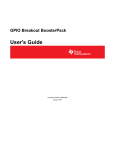
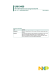
1
UM10722 SSL4120DB1123 - 90 W 1.9 A CC dimmable isolated LED driver demo board Rev. 1.1 — 19 August 2014 User manual Document information Info Content Keywords SSL4120T, LED driver, dimmable, isolated, demo board, power factor corrector, PFC, resonant, LLC, burst mode Abstract The SSL4120DB1123 is a dimmable global mains 90 W LED driver demo board featuring the NXP Semiconductors SSL4120T IC. The board has a two-stage (PFC + resonant) topology to achieve good THD performance (mains current class C compliance) over a wide mains input voltage range and output power range. The SSL4120DB1123 can drive a large LED voltage/current range. UM10722 NXP Semiconductors SSL4120DB1123 - 90 W 1.9 A CC dimmable LED driver Revision history Rev Date Description v 1.1 20140819 updated issue v.1 20130823 first issue Contact information For more information, please visit: http://www.nxp.com For sales office addresses, please send an email to: [email protected] UM10722 User manual All information provided in this document is subject to legal disclaimers. Rev. 1.1 — 19 August 2014 © NXP B.V. 2014. All rights reserved. 2 of 39 UM10722 NXP Semiconductors SSL4120DB1123 - 90 W 1.9 A CC dimmable LED driver 1. Introduction Warning Lethal voltage and fire hazard The non-insulated high voltages that are present when operating this product constitute a risk of electric shock, personal injury, death and/or ignition of fire. This product is intended for evaluation purposes only. It shall be operated in a designated test area by personnel qualified according to local requirements and labor laws to work with non-insulated mains voltages and high-voltage circuits. This product shall never be operated unattended. The SSL4120DB1123 demo board is a dimmable LED driver example using a PFC and an LLC stage. This manual describes the specification and use of the SSL4120DB1123 board. EMI filter PFC HB LLC LED output LED string DIM control DIM setting isolation mains SSL4120 T PFC + HB controller IC Fig 1. Demo board block diagram 1.1 Features and benefits • Efficient PFC and LLC topology • Large input voltage range • Short turn-on delay time • Low mains current harmonics • LLC stage with large output voltage range • Dimmable • Single layer PCB 146 x 60 mm, wave soldering UM10722 User manual All information provided in this document is subject to legal disclaimers. Rev. 1.1 — 19 August 2014 © NXP B.V. 2014. All rights reserved. 3 of 39 UM10722 NXP Semiconductors SSL4120DB1123 - 90 W 1.9 A CC dimmable LED driver 2. Safety warning The board must be connected to mains voltage. Avoid touching the demo board while it is connected to the mains voltage. An isolated housing is obligatory when used in uncontrolled, non-laboratory environments. Galvanic isolation of the mains phase using a variable transformer is always recommended. 019aab173 019aab174 a. Isolated Fig 2. b. Non isolated Variable transformer isolation symbols 3. Board specifications Table 1. Symbol UM10722 User manual Electrical specifications Description Value Condition V mains mains voltage (AC) 90 V to 300 V (AC) t d(on) turn-on delay time < 300 ms P o(max) maximum output power 90 W V o = 48 V Vo output voltage 15 V to 48 V CC mode V o(max) maximum output voltage 49 V fault mode, no LED 0.190 to 1.9 A DIM 10 % to 100 % [1] Io output current ∆I o /∆V mains line regulation <3% ∆I o /∆V o load regulation <3% V I(DIM) DIM input voltage 1 V to 10 V η efficiency > 90 % full load PF power factor > 0.95 full load THD total harmonic distortion < 10 % full load < 20 % quarter load no-load P i(fault) fault mode input power < 3.0 W P i(standby) [2] standby input power < 0.2 W [1] Average [2] P i(standby) is measured with pin SSHBC/EN shorted to ground All information provided in this document is subject to legal disclaimers. Rev. 1.1 — 19 August 2014 © NXP B.V. 2014. All rights reserved. 4 of 39 UM10722 NXP Semiconductors SSL4120DB1123 - 90 W 1.9 A CC dimmable LED driver 4. Demo board connections 4.1 Line voltage and LED module The mains voltage must connect to the IEC C6 type input connector J1. The LED module must connect to the LED output connector J6. J3 D IM J1 m a in s lin e J2 LED n e u tra l Fig 3. Mains connection and LED wiring 4.2 Dimming control secondary side The dimming controller must connect to the DIM input connector J3. The DIM input supports dimming control in two ways: • 1 V to 10 V interface: an external voltage applied to the DIM input; • External pull-down resistor. The output is at maximum output current when the DIM input is not connected. When the DIM input voltage is lower than 1.0 V the output current is 10 % of I o(max) . +13 V +13 V RINT RINT J3 LED driver DIM + VDIM 1 V to 10 V (DC) LED driver GND c. 1 V to 10 V DIM interface Fig 4. DIM J3 + - RDIM 0 kΩ to 100 kΩ GND d. External pull-down resistor DIM interface DIM input connections R INT = 4.7 kΩ; R DIM : 100 kΩ Logarithmic UM10722 User manual All information provided in this document is subject to legal disclaimers. Rev. 1.1 — 19 August 2014 © NXP B.V. 2014. All rights reserved. 5 of 39 UM10722 NXP Semiconductors SSL4120DB1123 - 90 W 1.9 A CC dimmable LED driver 5. Functional description The SSL4120DB1123 LED driver demo board is a dimmable constant current LED driver. This chapter describes some specific design choices for the LED driver. This driver board was especially designed to drive a wide LED voltage/current range. More information about the SSL4120T IC application is described in the SSSL4120T data sheet and the AN11227 application note. 5.1 SSL4120T controller IC The SSL4120T is a very robust and reliable PFC + resonant controller containing many features. The various internal protections ensure fail safe operation of the LED driver under all conditions. COMPPFC 1 24 SNSBOOST SNSMAINS 2 23 RCPROT SNSAUXPFC 3 22 SSHBC/EN SNSCURPFC 4 21 SNSFB SNSOUT 5 20 RFMAX SUPIC 6 GATEPFC 7 PGND 8 17 SNSCURHBC SUPREG 9 16 n.c. GATELS 10 15 HB 19 CFMIN IC 18 SGND n.c. 11 14 SUPHS SUPHV 12 13 GATEHS aaa-003401 Fig 5. SSL4120T IC pin out 5.2 Board topology The board topology is a PFC boost stage to meet the class C lighting requirements and an LLC resonant stage. UM10722 User manual All information provided in this document is subject to legal disclaimers. Rev. 1.1 — 19 August 2014 © NXP B.V. 2014. All rights reserved. 6 of 39 UM10722 NXP Semiconductors SSL4120DB1123 - 90 W 1.9 A CC dimmable LED driver D1 BYV25X-600 GND_SEC L2 696 μH / 2 A C1 100 pF / Y L1 2x20 mH / 1.5 A J1 MAINS BR1 GBU806 2 U R1 P300L 1 C2 220 nF / X2 310 V C4 220 nF / X2 310 V T1 500 μH C3 220 nF 630 V D2 BYV25X-600 9 7 C5 220 nF 630 V VBUS2 C6 47 μF 450 V Q1 FCPF7N60 R10 0.27 Ω R9 0.27 Ω VBUS2 GND_PRI Q2 FCPF7N60 T3 Lp = 710 μH Llk = 204 μH Np:Nsec = 5.545 6 4 Q3 FCPF7N60 C7 8.2 nF 1.6 kV 5 2 7 3 8 GND_PRI D4 BYQ28X-200 C11 47 μF 100 V L3 47 μH / 2 A C39 100 nF 100 V LED+ C45 100 nF 100 V C44 100 nF 100 V R69 0.050 Ω / 1 W J3 LED 1 2 LED- 1 D18 FM4007W C10 3.3 nF / Y GND_SEC GND_SEC Fig 6. Large signal path of the board 5.3 EMI filter The EMI filter consists of a differential mode inductor L2 and a common-mode inductor L1. The differential filter also includes C2, C3, C4 and C5. The common filter capacitors are C1 and C10. 5.4 Power Factor Correction (PFC) The PFC is a boost stage consisting of components T1, Q1, D2 and C6. In normal operation the PFC stage operates in boundary condition mode BCM with valley switching. The section “PFC controller” in the SSL4120T data sheet1 describes the valley switching. The design choices for the PFC stage are based on the following targets: • A wide mains input voltage range from 90 V (AC) to 305 V (AC) • A large output power range must comply with the mains current harmonics class C requirements for lighting equipment of IEC 61000-3-2 The PFC choke inductance is maximized (lowest PFC switching frequency) for a large frequency range. The maximum PFC frequency of the SSL4120T is limited to 380 kHz. The controller keeps the PFC frequency under 380 kHz with valley skipping. The operating mode of the PFC is DCM in case of valley skipping. A large PFC frequency range prevents discrete steps in the mains current which can be caused by the valley skipping. UM10722 User manual All information provided in this document is subject to legal disclaimers. Rev. 1.1 — 19 August 2014 © NXP B.V. 2014. All rights reserved. 7 of 39 UM10722 NXP Semiconductors SSL4120DB1123 - 90 W 1.9 A CC dimmable LED driver The relation between the PFC inductance and the PFC minimum switching frequency is shown in the following equation: 𝐿𝑃𝐹𝐶 = 𝑉𝑚𝑎𝑖𝑛𝑠 2 ×�𝑉𝑏𝑢𝑠(𝑛𝑜𝑚) −𝑉𝑚𝑎𝑖𝑛𝑠 � Where: 2×𝑓𝑠𝑤(𝑝𝑓𝑐)𝑚𝑖𝑛 ×𝑃𝑖 ×𝑉𝑏𝑢𝑠(𝑛𝑜𝑚) • L PFC = PFC inductance • V mains = AC mains voltage (RMS) • P i = input power • V bus(nom) = nominal bus voltage • f sw(pfc)min = PFC minimum switching frequency Table 2 shows the calculated minimum PFC switching frequency for many different conditions and three PFC inductances. Frequencies higher than 380 kHz are limited by the PFC controller by means of valley skipping. Table 2. V mains 90 V (AC) Calculated PFC minimum switching frequency f sw(pfc)mi n Pi L PFC = 250 µH L PFC = 500 µH 99 W 116 kHz 58 kHz L PFC = 750 µH 39 kHz 90 V (AC) 33 W 347 kHz 173 kHz 116 kHz 120 V (AC) 99 W 177 kHz 89 kHz 59 kHz 120 V (AC) 33 W 532 kHz 266 kHz 177 kHz 230 V (AC) 99 W 269 kHz 134 kHz 90 kHz 230 V (AC) 33 W 809 kHz 404 kHz 270 kHz 277 V (AC) 99 W 154 kHz 77 kHz 51 kHz 277 V (AC) 33 W 462 kHz 231 kHz 154 kHz The PFC inductance is 500 µH. Selecting a larger value can cause audible noise at a 300 V high mains voltage and full load because the PFC frequency drops significantly when the peak of the mains voltage is close to the bus voltage. The PFC output voltage V bus is dimensioned for the use of a 450 V rated bus capacitor. V bus(nom) = 435 V, the ripple is ±10 V. For 90 W a capacitor of 47 µF is sufficient when there are no holdup time (mains voltage cycle skipping) requirements. The PFC on-time t on(VGATEPFC) is modulated to increase near the zero crossings of V mains . The increase improves the THD and class C performance significantly. The modulation signal is injected using capacitor C22 into the compensation network on pin COMPPFC. The on-time is represented by the voltage V COMPPFC on pin COMPPFC. UM10722 User manual All information provided in this document is subject to legal disclaimers. Rev. 1.1 — 19 August 2014 © NXP B.V. 2014. All rights reserved. 8 of 39 UM10722 NXP Semiconductors SSL4120DB1123 - 90 W 1.9 A CC dimmable LED driver L1 2x20 mH / 1.5 A 3 4 C2 220 nF R7 1.5 MΩ R8 110 kΩ L2 696 μH / 2 A 2 Vmains 2 BR1 GBU806 1 4 C3 220 nF 3 1 GND_PFC R6 1.5 MΩ U3A SSL4120T R24 390 kΩ C22 1.2 nF 630 V R25 0Ω 3 R26 0Ω 8 2 1 C29 4.7 μF R29 R32 33 kΩ 39 kΩ SNSAUXPFC SNSMAINS PGND SUPHV GATEPFC SNSCURPFC COMPPFC SNSBOOST 12 7 4 24 GND_IC2 C24 100 nF GND_IC2 C25 470 nF GND_IC2 Fig 7. UM10722 User manual PFC on-time modulation with capacitor C22 All information provided in this document is subject to legal disclaimers. Rev. 1.1 — 19 August 2014 © NXP B.V. 2014. All rights reserved. 9 of 39 UM10722 NXP Semiconductors SSL4120DB1123 - 90 W 1.9 A CC dimmable LED driver Upper grid: C1 = V GATEPFC ; C2= l mains ; C4 = V bus Lower grid: C3 = V mains ; F1 = f (VGATEPFC) ; F2 = t on(VGATEPFC) Fig 8. PFC signals at V mains = 230 V (AC); V o = 48 V; I o = 1.9 A Channel F1 shows the frequency of the PFC gate drive signal V GATEPFC . During the zero crossing of V mains the valley skipping of the PFC controller is visible. Channel F2 shows the on time t on(VGATEPFC) of the PFC gate drive signal V GATEPFC . The THD in Fig 8 is about 5.6 %. UM10722 User manual All information provided in this document is subject to legal disclaimers. Rev. 1.1 — 19 August 2014 © NXP B.V. 2014. All rights reserved. 10 of 39 UM10722 NXP Semiconductors SSL4120DB1123 - 90 W 1.9 A CC dimmable LED driver Upper grid: C1 = V GPFC ; C2= l mains ; C4 = V bus Lower grid: C3 = V mains ; F1 = f (VGPFC) ; F2 = t on(VGPFC) Fig 9. PFC signals oscillogram at V mains = 230 V (AC); V o = 15 V; I o = 1.9 A At low load, the PFC frequency increases and the frequency limit of the PFC controller is reached. At the mains angle when the maximum PFC frequency is reached, the valley skipping is active. A discrete step in the mains current is present. The discrete steps and the flat line during the V mains zero crossing mostly determine the THD and class C performance. The THD in Fig 9 is about 13 %. UM10722 User manual All information provided in this document is subject to legal disclaimers. Rev. 1.1 — 19 August 2014 © NXP B.V. 2014. All rights reserved. 11 of 39 UM10722 NXP Semiconductors SSL4120DB1123 - 90 W 1.9 A CC dimmable LED driver 5.5 Half-bridge and LLC output stage The resonant circuit is a LLC topology driven with a half-bridge. The output section consisting of two diodes D4 is the standard half bridge rectification configuration. The LLC output is constant current regulated, intended to drive LED modules as a current source. The LLC design choices are based on the following targets: • High efficiency at full load / normal operating conditions • Large output voltage range support Vbus C15 Q2 T3 Llk 204 μH Lsec N = 5.545 Lm 506 μH C23 Q3 Vo D4 C11 C7 8.2 nF Laux N = 8.71 Fig 10. Simplified LLC circuit with integrated transformer An integrated LLC transformer with m = 3.5 (m = L p / L lk and Lp = L m + L lk ) is used because a smaller frequency range is required to reach a lower V o compared to m = 5 or m = 7. 55 Vo [V] 50 Lm = 1200 µH 45 40 Lm = 800 µH 35 30 25 Lm = 500 µH 20 15 10 Llk = 200 µH, Rload = 80 Ω 5 0 100 120 140 160 180 200 220 240 260 280 300 fsw(HBC) [kHz] Fig 11. LLC voltage transfer for different m = L p / L lk values with 80 Ω load Increasing the capacitance values of C15 and C23 (currently 47 pF) helps to reach a UM10722 User manual All information provided in this document is subject to legal disclaimers. Rev. 1.1 — 19 August 2014 © NXP B.V. 2014. All rights reserved. 12 of 39 UM10722 NXP Semiconductors SSL4120DB1123 - 90 W 1.9 A CC dimmable LED driver slightly lower output voltage level. 5.6 Burst mode LLC operation The large V o and I o range is achieved by the implemented burst mode of the LLC stage. Burst mode operation is implemented to increase the output power range. At I o = 100 %; burst is active under 28 V At I o = 10 %; burst is active under 38 V The drawback of the burst mode is possible audible noise and ripple of the LED current causing visible flicker. The resonant capacitor C7 is a film capacitor because ceramic capacitors can cause audible noise. To prevent visible flicker, the burst frequency is kept well above 1 kHz. Q2 FCPF7N60 15 16 17 18 C14 180 pF 20 21 C20 470 nF R16 75 kΩ 22 23 SUPHS NC1 HB GATELS NC2 SUPREG 10 9 Q3 FCPF7N60 SUPREG C31 470 nF SNSCURHBC C28 2.2 μF SGND RFMAX C23 47 pF 6 SUPIC CFMIN GND_PRI 5 SNSOUT C7 8.2 nF 1.6 kV 6 4 5 2 7 3 8 1 SNSFB SSHBC/EN GND_PRI RCPROT R38 330 kΩ C17 2.2 μF R3 10 Ω R35 0Ω U2 SFH615A-4 WB5 4 C19 1 nF T3 D12 BAS316 GND_PRI C27 10 nF R36 27 kΩ R49 15 kΩ NM C32 2.2 nF GND_PRI GND_PRI 3 R15 15 kΩ 19 C15 47 pF 11 1 14 U3B SSL4120T GATEHS 2 13 GND_PRI SUPREG 8 D14 BAV99 R46 2.2 kΩ R40 100 kΩ R43 8.2 kΩ Q4 BC846B 5 7 6 U4B LM2903PWR 4 U4C LM2903PWR U4A LM2903PWR 2 1 3 R42 33 kΩ R45 33 kΩ R47 3.3 kΩ C33 10 nF R44 33 kΩ C34 2.2 nF GND_PRI Fig 12. LLC burst mode control diagram V SNSFB is an input of the half-bridge frequency control. V SNSFB is also used as input for the burst mode comparator U4B. The PFC is always active (including bust mode) because bursting the PFC reduces the THD performance. Therefore, V SNSOUT is kept above 0.5 V with a diode D14 in series with the collector on Q4. In burst mode, the HB stage is stopped and started via pin SNSOUT, the external UM10722 User manual All information provided in this document is subject to legal disclaimers. Rev. 1.1 — 19 August 2014 © NXP B.V. 2014. All rights reserved. 13 of 39 UM10722 NXP Semiconductors SSL4120DB1123 - 90 W 1.9 A CC dimmable LED driver comparator circuit sets the burst mode level and hysteresis parameters. • Burst level: set the half-bridge frequency during burst f hbc(burst) with resistors R42 and R44 (set to 230 kHz); • Burst hysteresis: adjust the burst repetition frequency f hbc(burst) with resistor R40. In addition to the hysteresis setting of the burst mode comparator, other items influence the minimum burst frequency. In general, using a smaller hysteresis and a faster control loop results in fewer burst pulses, higher burst frequency and low output current ripple. Table 3. Item Minimum burst mode frequency tuning Effect hysteresis burst mode comparator less hysteresis fewer pulses higher f burst(min) LLC output capacitor less capacitance fewer pulses higher f burst(min) LLC CC control loop speed more gain fewer pulses higher f burst(min) The control loop gain is influenced by the following board components: The optocoupler current transfer ratio (CTR), R70, C41, C40, R65, R61, U6B, LLC circuit, C19, R15 = R RFMAX , C14 = C CFMIN . Upper grid: C1 = V o ; C2= l o ; C3 = V SNSFB ; C4 = V HB Lower grid: Z1 = zoom (C1); Z2 = zoom (C2); Z3 = zoom (C3); Z4 = zoom (C4); Fig 13. Output signals oscillogram at V o = 16 V; I o = 0.19 A (real LED load) The minimum burst frequency f burst(min) occurs at condition V o(min) and I o(min) . Because f burst(min) is well above 1 kHz, therefore visible flicker is not an issue3. UM10722 User manual All information provided in this document is subject to legal disclaimers. Rev. 1.1 — 19 August 2014 © NXP B.V. 2014. All rights reserved. 14 of 39 UM10722 NXP Semiconductors SSL4120DB1123 - 90 W 1.9 A CC dimmable LED driver 5.7 IC low-voltage supply circuit An additional auxiliary winding on the PFC transformer provides the SSL4120T lowvoltage supply at pin SUPIC. Because the bus voltage is regulated, the PFC auxiliary winding with a full bridge rectifier generates a fixed supply. Because the fixed supply is independent of V o , it is also independent of the number of LEDs attached in series. Once the PFC starts switching, the PFC auxiliary winding almost immediately charges the SUPIC buffer capacitor C8. The capacitance C26 on pin SUPIC can be small and a short turn-on delay is achieved. D10 BAV23S D9 BAV23S T1 PFC transformer 7 9 R39 1Ω C8 220 μF 3 10 13 14 1 13 14 15 16 17 18 19 20 21 22 23 GND_PRI T3 LLC transformer 12 6 U3B SSL4120T GATEHS SUPHS NC1 HB GATELS NC2 SUPREG SUPIC SNSOUT 2 3 GND_PRI 8 1 9 D8 BAS316 SGND RFMAX 5 7 11 10 SNSCURHBC CFMIN 4 6 5 D11 BAS316 D13 BZX84J-C12 C26 470 nF SNSFB SSHBC/EN GND_PRI RCPROT GND_PRI Fig 14. Low-voltage supply diagram In case of fault/no-load conditions the PFC NMOST gate pulses are too short for the transformer to transfer energy to the IC supply. V o increases to V o(max) and the auxiliary winding voltage of the LLC transformer also increases. The auxiliary winding of the LLC transformer takes over the supply from the PFC auxiliary winding. D13 is in series with D11 because the voltage of the LLC auxiliary winding is normally too high and can cause unnecessary power dissipation. Table 4. V mains UM10722 User manual Turn-on delay times t d(on) 100 V (AC); 60 Hz 272 ms 120 V (AC); 50 Hz 213 ms 230 V (AC); 60 Hz 125 ms 277 V (AC); 60 Hz 129 ms All information provided in this document is subject to legal disclaimers. Rev. 1.1 — 19 August 2014 © NXP B.V. 2014. All rights reserved. 15 of 39 UM10722 NXP Semiconductors SSL4120DB1123 - 90 W 1.9 A CC dimmable LED driver (1) C1 = I o ; C2 = V o ; C4 = V mains Fig 15. Turn-on delay time oscillogram at 100 V (AC); 60 Hz UM10722 User manual All information provided in this document is subject to legal disclaimers. Rev. 1.1 — 19 August 2014 © NXP B.V. 2014. All rights reserved. 16 of 39 UM10722 NXP Semiconductors SSL4120DB1123 - 90 W 1.9 A CC dimmable LED driver 5.8 LLC feedback control loop The LED driver incorporates two regulation features: • A Constant Voltage (CV) regulation • A Constant Current (CC) regulation In normal operation the CC loop is closed and the CV loop is open. The set point of the LED output current is controlled with the DIM input signal. D4 BYQ28X-200 L3 47 μH / 2 A Vo 4 6 1 5 2 7 3 8 1 C11 47 μF 2 C39 100 nF R69 0.050 Ω / 1 W 3 R62 24 kΩ +13 V C44 100 nF 4 D18 FM4007W Vo T3 Lp = 710 μH Llk = 204 μH Np:Nsec = 5.545 C45 100 nF J2 LED 1 LED- +13V R70 2.2 kΩ R67 270 kΩ Q6 BCP56-16 R74 100 Ω R68 4.7 kΩ Q7 BC846B J3 DIM 1 R59 59 kΩ D17 BAS316 DIM 2 GND U5 TLVH431 R71 3.3 kΩ R56 6.2 kΩ CC Set point CC closed loop R65 27 Ω R63 0Ω C40 220 nF D16 BAW56 5 C41 7 1 nF 6 U6B LM2904AV R64 CV 0Ω closed loop U6A LM2904AV 3 1 2 C36 220 nF R72 27 kΩ R73 22 kΩ C43 1 nF Vo R52 82 kΩ +13 V CV Set point R53 9.1 kΩ R60 33 kΩ C37 100 pF R55 8.2 kΩ C42 1 nF R58 22 kΩ R54 5.1 kΩ 8 C35 4.7 μF 1 2 3 4 U2 SFH615A-4 R66 330 kΩ C38 1 nF U6C LM2904AV 4 R61 1.8 kΩ LED+ 2 Fig 16. LLC control loop error amplifiers and output section of the LLC stage The DIM input signal can reduce the CC set point. C37, C38, C43, C47 are placed to prevent HF noise from entering the control loop. UM10722 User manual All information provided in this document is subject to legal disclaimers. Rev. 1.1 — 19 August 2014 © NXP B.V. 2014. All rights reserved. 17 of 39 UM10722 NXP Semiconductors SSL4120DB1123 - 90 W 1.9 A CC dimmable LED driver Vo [V] Vo [V] operating point no-load RLOAD = 20 Ω CV limit = 49 R LOAD = 33 Ω CV limit = 49 Vo = 38 e ad ve operating point R LOAD = 33 Ω lin lo ti sis operating point re 15 15 0.0 Io [A] CC limit = 1.9 A 0.19 0.0 a. Resistive load line, no dimming, CC operation Io = 1.5 CC limit = 1.9 A 0.19 Io [A] b. Resistive load line, no dimming, CV operation Fig 17. I-V diagrams of LED driver with constant voltage and constant current regulation 5.9 LED current control The DIM input controls the constant current regulation set point which is derived from the accurate 13 V supply regulated with U5. The set point varies from 10 mV to 100 mV. • Resistors R66, R71 and R67 set the 10 mV lower limit. • Resistors R66, R71, R68 and R73 set the 100 mV upper limit. The 13 V local supply draws current from V o . The current is minimized by using a low current shunt regulator TLVH431 and a high gain optocoupler. The dissipation in Q6 is minimal for the specified V o range. 120 VR 71 (mV) 100 80 60 40 20 0 0 2 4 6 8 10 Vi(D IM ) (V) 12 Fig 18. Current control set point as function of DIM input voltage UM10722 User manual All information provided in this document is subject to legal disclaimers. Rev. 1.1 — 19 August 2014 © NXP B.V. 2014. All rights reserved. 18 of 39 UM10722 NXP Semiconductors SSL4120DB1123 - 90 W 1.9 A CC dimmable LED driver Fig 19b shows a typical load line of an LED module. The voltage slightly decreases while the LED module is dimmed. Vo [V] Vo [V] R LOAD = 27 Ω CV limit = 49 CV limit = 49 operating point Vo = 38 15 re e ti v s i s d l oa LED module load line Vo = 42 e li n operating point dimming 15 dimming I o = 1.4 0.0 0.19 CC limit = 1.4 A Io = 1.0 Io [A] 1.9 0.0 a. Resistive load line, with dimming, CC operation 0.19 CC limit = 1.0 A Io [A] 1.9 b. LED load line, with dimming, CC operation Fig 19. I-V diagrams of LED driver with constant voltage and constant current regulation 5.10 Output voltage control Operation without a LED module connected is considered a ‘fault mode’ because the LED driver is intended to be connected with a LED module. The voltage control limits the output voltage when no load is connected or when an LED string is broken. When the voltage control loop is closed the CC loop is open. In CV mode the output is V o is regulated at V o(max) = 49 V. UM10722 User manual All information provided in this document is subject to legal disclaimers. Rev. 1.1 — 19 August 2014 © NXP B.V. 2014. All rights reserved. 19 of 39 UM10722 NXP Semiconductors SSL4120DB1123 - 90 W 1.9 A CC dimmable LED driver 5.11 Output short conditions Several features provide protection against component damage when the LED output is shorted. Two conditions must be considered: • Short at start-up • Short during operation The SSL4120T protection features involved during output short are: • LLC current sense input SNSCURHBC via sense resistor R41 • Half-bridge switching node voltage sense input HB • Protection timer RCPROT pin with components R16 and C17 The output undervoltage protection via pin SNSOUT is disabled by the application to support the large V o range. Q2 FCPF7N60 T3 Lp = 710 μH Lk = 204 μH N = 5.545 C15 47 pF Q3 FCPF7N60 D4 BYQ28X-200 6 4 5 2 7 3 L3 47 μH/2 A Vo 1 C23 47 pF C7 8.2 nF 1.6 kV C9 330 pF 1 kV GND_PRI 8 R41 9.1 Ω 13 14 15 R19 1 kΩ C13 1 nF 16 17 18 C14 180 pF R15 15 kΩ 19 20 21 C20 470 nF R16 75 kΩ 22 23 C11 47 μF 2 C39 100 nF R69 0.050 Ω/1 W 1 3 4 C45 100 nF C44 100 nF J2 LED 1 LED+ 2 LED- D18 FM4007W U3B SSL4120T GATEHS NC1 SUPHS HB GATELS NC2 SUPREG 11 10 9 SNSCURHBC SGND CFMIN SUPIC RFMAX SNSOUT 6 5 SNSFB SSHBC/EN RCPROT C17 2.2 μF GND_PRI Fig 20. Part of the circuit diagram relevant for output short conditions 5.11.1 Output short at start-up The SSL4120T performs a soft start. It starts at the highest half-bridge frequency and then ramps down. The half-bridge current is sensed via pin SNSCURHBC and the controller starts to regulate the half-bridge frequency using pin SSHBC/EN when V SNSCURHBC > 0.5 V. During the current regulation the RCPROT fault timer is activated and C17 is charged. The RCPROT fault timer ends when V RCPROT > 4.0 V. The controller stops switching. C17 is discharged by resistor R16 when the fault timer is inactive. The RCPROT timer duty cycle can be programmed by the application, which enables adjustment of the average input power during a short circuit. UM10722 User manual All information provided in this document is subject to legal disclaimers. Rev. 1.1 — 19 August 2014 © NXP B.V. 2014. All rights reserved. 20 of 39 UM10722 NXP Semiconductors SSL4120DB1123 - 90 W 1.9 A CC dimmable LED driver C1 = V SNSCURHBC ; C2 = V RCPROT ; C3 = V SUPIC ; C4 = V SSHBC/EN Fig 21. Output short during start-up oscillogram UM10722 User manual All information provided in this document is subject to legal disclaimers. Rev. 1.1 — 19 August 2014 © NXP B.V. 2014. All rights reserved. 21 of 39 UM10722 NXP Semiconductors SSL4120DB1123 - 90 W 1.9 A CC dimmable LED driver 5.11.2 Output short during operation During operation the output capacitor is charged. Diode D18 (parallel to the LED current sense resistor) limits the sense voltage and protects the sense resistor and error amplifier. (1) (2) (3) (4) C1 = V SNSCURHBC ; C2 = V RCPROT ; C3 = V HB ; C4 = V SSHBC/EN Fig 22. Output short with switch during operation at no load oscillogram (1) Before output short, V o = V o(max) (2) Adaptive non-overlap function delays the HBC oscillator to prevent hazardous switching of the half-bridge MOSFETs. The soft start capacitor C20 on pin SSHBC/EN is discharged. The SSL4120T tries to regulate the frequency to the border between capacitive and inductive mode of the LLC. (3) V (ocp)HBC = 1.0 V is triggered via pin SNSCURHBC. The oscillator frequency is immediately set to the maximum frequency. (4) Half-bridge running at the maximum frequency of 330 kHz until the RCPROT timer ends. UM10722 User manual All information provided in this document is subject to legal disclaimers. Rev. 1.1 — 19 August 2014 © NXP B.V. 2014. All rights reserved. 22 of 39 UM10722 NXP Semiconductors SSL4120DB1123 - 90 W 1.9 A CC dimmable LED driver 6. Mains input measurements 6.1 Efficiency Table 5. V mains Efficiency P o = 100 % P o = 50 % P o = 33 % P o = 25 % 100 V (AC); 60 Hz 90.3 % 87.8 % 89.4 % 88.1 % 120 V (AC); 60 Hz 91.3 % 88.3 % 89.9 % 88.2 % 230 V (AC); 50 Hz 93.1 % 89.0 % 90.1 % 88.0 % 277 V (AC); 60 Hz 93.0 % 88.8 % 89.3 % 87.1 % P o = 100 % P o = 50 % P o = 33 % P o = 25 % 100 V (AC); 60 Hz 0.9982 0.9966 0.9932 0.9872 120 V (AC); 60 Hz 0.9977 0.9937 0.9880 0.9799 230 V (AC); 50 Hz 0.9894 0.9698 0.9425 0.9078 277 V (AC); 60 Hz 0.9738 0.9198 0.8629 0.7927 P o = 33 % P o = 25 % 6.2 Power factor Table 6. V mains Power factor 6.3 Mains current total harmonic distortion Table 7. V mains UM10722 User manual Mains current total harmonic distortion P o = 100 % P o = 50 % 100 V (AC); 60 Hz 3.74 % 2.93 % 4.55 % 6.45 % 120 V (AC); 60 Hz 3.30 % 3.81 % 6.43 % 8.68 % 230 V (AC); 50 Hz 5.59 % 9.83 % 12.7 % 15.0 % 277 V (AC); 60 Hz 9.12 % 16.2 % 18.1 % 19.1 % All information provided in this document is subject to legal disclaimers. Rev. 1.1 — 19 August 2014 © NXP B.V. 2014. All rights reserved. 23 of 39 UM10722 NXP Semiconductors SSL4120DB1123 - 90 W 1.9 A CC dimmable LED driver 6.4 Mains current harmonics Imains 140 [mA] 120 100 80 full load 60 IEC limit 40 20 0 2 3 5 7 9 11 13 15 17 19 21 23 25 27 29 31 33 35 37 39 mains current harmonics order Fig 23. IEC 61000-3-2 mains current harmonics class C compliance at 230 V (AC); 50 Hz; full load 6.5 No-load input power The no-load input power is measured with nothing connected to connectors J2 (LED) and J3 (DIM). Table 8. V mains No load power measurement P i(standby) I mains 100 V (AC); 60 Hz 2.41 W 42.8 mA 120 V (AC); 60 Hz 2.43 W 43.3 mA 230 V (AC); 50 Hz 2.15 W 47.1 mA 277 V (AC); 60 Hz 2.09 W 45.8 mA 6.6 Standby input power Some LED drivers have a standby power supply and a microcontroller to control a main power supply. When using the SSL4120T in the main power supply, a microcontroller can pull-down pin SSHBC/EN using a transistor. The standby input power is measured while the pin SSHBC/EN is shorted to ground. Table 9. V mains UM10722 User manual Standby input power measurement P i(standby) I mains 120 V (AC); 60 Hz 43 mW 30.0 mA 230 V (AC); 50 Hz 117 mW 35.4 mA 277 V (AC); 60 Hz 130 mW 44.9 mA All information provided in this document is subject to legal disclaimers. Rev. 1.1 — 19 August 2014 © NXP B.V. 2014. All rights reserved. 24 of 39 UM10722 User manual All information provided in this document is subject to legal disclaimers. Rev. 1.1 — 19 August 2014 2 HS2 Secondary heatsink HEATSINKS 1 C1 100 pF GNDC FH1 2.5 AT R1 P300L E1 EARTH U R7 1.5 MΩ C4 220 nF 2 GND_PFC 1 HS1 Primary heatsink 2 3 C2 220 nF C22 1.2 nF 630 V R24 390 kΩ R6 1.5 MΩ 1 4 L1 2 x 20 mH / 1.5 A GNDC MH2 MH1 MH4 MH3 3mm5 3mm5 3mm5 3mm5 MOUNTING HOLES wire to E1 and E2 from mains connector R8 110 kΩ E2 EARTH 1 2 J1 MAINS R26 0Ω R25 0Ω 4 3 2 NM=NOT MOUNTED C24 100 nF 12 10 3 13 2 1 8 SNSCURPFC GATEPFC SUPHV 24 4 7 R14 GND_PFC C8 220 μF R22 51 kΩ R18 0Ω C30 220 pF R4 1 kΩ R5 2.21 Ω R28 0Ω R12 3.3 MΩ R13 3.3 MΩ 3.3 MΩ R39 1Ω GND_IC GND_IC2 C21 1 nF R20 5.6 kΩ COMPPFC SNSBOOST PGND SNSMAINS SNSAUXPFC U3A SSL4120T R33 5.1 kΩ 12 R2 1Ω R37 GND_PFC GND_PFC 0Ω 3 1 GND_IC2 R31 15 kΩ GND_IC2 C25 470 nF R32 33 kΩ 39 kΩ R29 14 T1 500 μH 9 7 D1 BYV25X-600 GND_STAR GND_IC2 GND_PFC C3 C5 220 nF 220 nF GND_IC2 C29 4.7 μF 1 BR1 GBU806 L2 696 μH / 2 A D9 BAV23S D10 BAV23S R27 0Ω R10 0.27 Ω W1 W2 GND_PFC R9 0.27 Ω C12 47 pF NM W4 W3 C6 47 μF 450 V WB1 Q1 FCPF7N60 D2 BYV25X-600 VBUS2 GND_PFC GND_STAR GND_HB GND_IC2 C16 33 nF R17 22 kΩ R11 10 Ω D5 BAS316 GND_IC SUPIC NXP Semiconductors UM10722 SSL4120DB1123 - 90 W 1.9 A CC dimmable LED driver 7. Schematic Fig 24. Mains input and PFC stage © NXP B.V. 2014. All rights reserved. 25 of 39 GND_IC R16 75 kΩ R15 15 kΩ C13 1 nF WB3 C19 1 nF C17 2.2 μF C20 470 nF U4C LM2903PWR WB2 R21 10 Ω GND_IC2 C27 10 nF R47 3.3 kΩ R43 8.2 kΩ WB5 U4A LM2903PWR 2 1 3 R3 10 Ω Q4 BC846B D14 BAV99 R36 27 kΩ R35 0Ω U3B SSL4120T 13 GATEHS 11 14 R30 NC1 SUPHS 10 Ω 10 15 HB GATELS 9 16 NC2 SUPREG 17 C31 SNSCURHBC 470 nF 18 SGND 6 19 SUPIC CFMIN 5 20 C26 RFMAX SNSOUT 470 nF 21 SNSFB 22 SSHBC/EN GND_IC2 23 RCPROT GND_IC2 C14 180 pF R19 1 kΩ D3 UF4006 SUPREG C18 330 nF SNSCURHBC SUPREG R40 100 kΩ R42 33 kΩ C33 10 nF 6 5 SUPIC R44 33 kΩ GND_IC2 C32 2.2 nF R38 330 kΩ D8 BAS316 U4B LM2903PWR 7 R45 33 kΩ GND_IC2 WB6 C23 47 pF WB4 Q3 FCPF7N60 C15 47 pF Q2 FCPF7N60 SUPREG C28 GND_HB 2.2 μF SNSCURHBC R34 22 Ω D7 BAS316 R23 22 Ω D6 BAS316 C34 2.2 nF R46 2.2 kΩ C7 8.2 nF 1.6 kV R51 3.9 kΩ NM R58 22 kΩ C36 220 nF D18 FM4007W C42 1 nF C37 100 pF C41 1 nF U5 TLVH431 U6A LM2904AV 3 1 2 5 1 Vo R54 5.1 kΩ R53 9.1 kΩ R72 27 kΩ R68 4.7 kΩ R55 8.2 kΩ R60 33 kΩ +13V C38 1 nF R71 3.3 kΩ R66 330 kΩ Q7 BC846B R67 270 kΩ +13V R52 82 kΩ R70 2.2 kΩ 4 2 L3 47 μH/2 A R69 0.050 Ω / 1 W 3 C39 100 nF R62 24 kΩ U1 SFH615A-4 NM 7 C40 220 nF R65 27 Ω C11 47 μF Vo D15 BZX84-C51 NM D16 BAW56 R63 0Ω NM=NOT MOUNTED R50 10 kΩ NM Q5 BC846B NM Vo GND_IC2 R57 10 kΩ R56 NM 6.2 kΩ R59 C35 4.7 μF 59 kΩ Q6 BCP56-16 Vo D4 BYQ28X-200 6 U6B LM2904AV R64 0Ω U2 SFH615A-4 R61 1.8 kΩ +13V T3 Lp = 710 μH Llk = 204 μH Np:Nsec = 5.545 1 3 8 2 5 4 7 6 R48 10 kΩ NM R49 15 kΩ NM D13 BZX84J-C12 D12 BAS316 D11 BAS316 R41 9.1 Ω C9 330 pF 1 kV GND_PFC C10 3.3 nF / Y2 1 2 VBUS2 8 4 4 3 1 4 Rev. 1.1 — 19 August 2014 3 All information provided in this document is subject to legal disclaimers. 2 User manual U6C LM2904AV C43 1 nF D17 BAS316 R74 100 Ω C44 100 nF C45 100 nF R73 22 kΩ 8 UM10722 4 1 2 1 2 J3 DIM J2 LED GND DIM LED- LED+ NXP Semiconductors UM10722 SSL4120DB1123 - 90 W 1.9 A CC dimmable LED driver Fig 25. LLC stage and LED output © NXP B.V. 2014. All rights reserved. 26 of 39 UM10722 NXP Semiconductors SSL4120DB1123 - 90 W 1.9 A CC dimmable LED driver 8. PCB layout The PCB board information: • Wave soldering • Single layer • Component numbering is starting at the mains connector • Some holes are added where possible for experimentation Fig 26. PCB top side component placing Fig 27. PCB bottom side copper and component placing UM10722 User manual All information provided in this document is subject to legal disclaimers. Rev. 1.1 — 19 August 2014 © NXP B.V. 2014. All rights reserved. 27 of 39 UM10722 NXP Semiconductors SSL4120DB1123 - 90 W 1.9 A CC dimmable LED driver 9. Transformer information 9.1 PFC transformer Wurth Electronics Midcom Inc.; part number 750313715 12 12 1 10 9 5 3 1 37 1 1 3 50 9 3 7 7 4 7 10 6 a. Bottom view b. Top view c. Winding pin out Fig 28. PFC transformer drawings Table 10. PFC transformer electrical specifications Symbol Parameter Value Condition Lp inductance 500 µH I sat saturation current 3.5 A N turns ratio 17.33 (9-7):(12-1) 13.00 (9-7):(3-10) L lk leakage inductance 40 µH tie 1 + 3 + 10 + 12 Vε Dielectric rating 1000 V (AC) pins 1 to 7 R dc UM10722 User manual DC resistance pins 7 to 9 1000 V (AC) pins 3 to 7 2000 V (AC) pin 7 to core 260 mΩ pins 7 to 9 100 mΩ pins 3 to 10 200 mΩ pins 1 to 12 All information provided in this document is subject to legal disclaimers. Rev. 1.1 — 19 August 2014 © NXP B.V. 2014. All rights reserved. 28 of 39 UM10722 NXP Semiconductors SSL4120DB1123 - 90 W 1.9 A CC dimmable LED driver 9.2 Integrated LLC transformer ITACOIL PCB inductive components; part number TRLEV25048A-150213A TRLEV25048A-150213A a. Bottom view b. Side view Fig 29. LLC transformer drawings Table 11. Symbol User manual [1] Condition Lp effective series inductance 710 µH pins 5 to 6 L lk leakage inductance 204 µH tie pins (1 + 2 + 3 + 4 + 7 + 8) m inductance ratio L p /L lk 3.48 N p :N sec primary turns to secondary turns ratio 5.545 N p :N aux primary turns to auxiliary turns ratio 8.714 V bus bus voltage 435 V f sw(HB)nom nominal half-bridge switching frequency 116 kHz Cr resonance capacitor 8.2 nF [1] UM10722 LLC transformer electrical specifications Parameter Value (5-6):(1-2) (5-6):(3-4) (5-6):(7-8) V o = 48 V; P o = 90 W L p = L lk + L m All information provided in this document is subject to legal disclaimers. Rev. 1.1 — 19 August 2014 © NXP B.V. 2014. All rights reserved. 29 of 39 UM10722 NXP Semiconductors SSL4120DB1123 - 90 W 1.9 A CC dimmable LED driver 10. EMI measurement dBµV 100 kHz 100 LIMIT CHECK 1 MHz PASS 10 MHz 90 1 PK MAXH 2 AV MAXH 80 TDF 70 FCC15BVQ 60 FCC15BVA 50 6DB 40 30 20 10 0 30 MHz 9 kHz Fig 30. Conducted emission pre-scan L and N; V mains = 115 V (AC) dBµV 100 kHz 120 LIMIT CHECK 1 MHz PASS 10 MHz EN55015Q 110 1 PK MAXH 2 AV MAXH 100 TDF 90 80 70 6DB 60 EN55015A 50 40 30 20 30 MHz 9 kHz Fig 31. Conducted emission pre-scan L and N; V mains = 230 V (AC) UM10722 User manual All information provided in this document is subject to legal disclaimers. Rev. 1.1 — 19 August 2014 © NXP B.V. 2014. All rights reserved. 30 of 39 UM10722 NXP Semiconductors SSL4120DB1123 - 90 W 1.9 A CC dimmable LED driver dBµV 100 100 kHz LIMIT CHECK 1 MHz PASS 10 MHz 90 1 PK MAXH 2 AV MAXH 80 TDF 70 FCC15BVQ 60 FCC15BVA 50 6DB 40 30 20 10 0 30 MHz 9 kHz Fig 32. Conducted emission pre-scan results L and N; V mains = 277 V (AC) UM10722 User manual All information provided in this document is subject to legal disclaimers. Rev. 1.1 — 19 August 2014 © NXP B.V. 2014. All rights reserved. 31 of 39 UM10722 NXP Semiconductors SSL4120DB1123 - 90 W 1.9 A CC dimmable LED driver 11. Thermal measurement Fig 33. Thermal camera photograph top side PCB; V mains = 90 V (AC); full load Fig 34. Thermal camera photograph bottom side PCB; V mains = 90 V (AC); full load UM10722 User manual All information provided in this document is subject to legal disclaimers. Rev. 1.1 — 19 August 2014 © NXP B.V. 2014. All rights reserved. 32 of 39 UM10722 NXP Semiconductors SSL4120DB1123 - 90 W 1.9 A CC dimmable LED driver 12. Bill Of Materials (BOM) Table 12. Bill of materials Part Reference Description and values Manufacturer Part Number Manufacturer BR1 bridge rectifier; 8 A; 600 V GBU806 Diode Inc C1 capacitor; 100 pF; 10 %; 440 V; Y2 VY2101K29Y5SG63V7 Vishay C2; C4 capacitor; 220 nF; 20 %; 310 V; X2 BFC233922224 Vishay C3; C5 capacitor; 220 nF; 5 %; 630 V ECW-FA2J224J Panasonic C6 capacitor; 47 µF; 20 %; 450 V EEUEE2W470S Panasonic C7 capacitor; 8.2 nF; 5 %; 1.6 kV B32672L1822J000 Epcos C8 capacitor; 220 µF; 20 %; 35 V UPJ1V221MPD1TD Nichicon C9 capacitor; 330 pF; 5 %; 1 kV DEA1X3A331JA2B Murata C10 capacitor; 3.3 nF; 20 %; 300 V; Y2 B32021A3332M Epcos C11 capacitor; 47 µF; 20 %; 100 V UBT2A470MPD Nichicon C12 capacitor; not mounted; 47 pF; 5 %; 630 V; C0G; 1206 GRM31A5C2J470JW01D Murata C15; C23 capacitor; 47 pF; 5 %; 630 V; C0G; 1206 GRM31A5C2J470JW01D Murata C13; C19; C21; C38; C41; C42; C43 capacitor; 1 nF; 10 %; 50 V; C0G; 0603 C0603C102K5GAC Kemet C14 capacitor; 180 pF; 1 %; 50 V; C0G; 0603 GRM1885C1H181FA01D Murata C16 capacitor; 33 nF; 10 %; 50 V; X7R; 0603 C0603C333K5RACTU Kemet C17; C28 capacitor; 2.2 µF; 10 %; 16 V; X7R; 0805 CC0805KKX7R7BB225 Yageo C18 capacitor; 330 nF; 10 %; 50 V; X7R; 0603 C1608X7R1H334K TDK C20; C25; C26; C31 capacitor; 470 nF; 10 %; 50 V; X7R; 0603 C1608X7R1H474K TDK C22 capacitor; 1.2 nF; 5 %; 630 V; C0G; 1206 C3216C0G2J122J TDK C24 capacitor; 100 nF; 10 %; 50 V; X7R; 0603 C0603C104K5RACTU Kemet C27; C33 capacitor; 10 nF; 10 %; 50 V; X7R; 0603 C0603C103K5RACTU Kemet C29; C35 capacitor; 4.7 µF; 10 %; 25 V; X7R; 0805 TMK212AB7475KG-T Taiyo Yuden C30 capacitor; 220 pF; 5 %; 50 V; C0G; 0603 C0603C221J5GACTU Kemet C32; C34 capacitor; 2.2 nF; 10 %; 50 V; X7R; 0603 C0603C222K5RAC7411 Kemet C36; C40 capacitor; 220 nF; 10 %; 25 V; X7R; 0603 GRM188R71E224KA88D Murata C37 capacitor; 100 pF; 5 %; 100 V; C0G ; 0603 GRM1885C2A101JA01J Murata C39; C44; C45 capacitor; 100 nF; 10 %; 100 V; X7R; 0603 GRM188R72A104KA35D Murata D1; D2 diode; 600 V; 5 A; TO220F-2P BYV25X-600,127 NXP Semiconductors D3 diode; 800 V; 1 A UF4006-E3/73 Vishay D4 diode; dual; 200 V; 10 A BYQ28X-200,127 NXP Semiconductors D5; D6; D7; D8; D11; D12; D17 diode; 100 V; 215 mA BAS316,135 NXP Semiconductors D9; D10 diode; dual; 200 V; 225 mA BAV23S,215 NXP Semiconductors D13 diode; zener; 12 V; 550 mW; SOD323F BZX84J-C12,115 NXP Semiconductors UM10722 User manual All information provided in this document is subject to legal disclaimers. Rev. 1.1 — 19 August 2014 © NXP B.V. 2014. All rights reserved. 33 of 39 UM10722 NXP Semiconductors SSL4120DB1123 - 90 W 1.9 A CC dimmable LED driver D14 diode; dual; 100 V; 215 mA BAV99,215 NXP Semiconductors D15 diode; zener; not mounted; 51 V; 250 mW, SOT-23 BZX84-C51,215 NXP Semiconductors D16 diode; dual; 90 V; 215 mA BAW56,235 NXP Semiconductors D18 diode; 1 kV; 1 A; SMX FM4007W-W Rectron FH1 fuse; 2 A; slow SS-5H-2A-APH Cooper Bussmann J1 mains inlet with solder tab 771W-BX2/01 Qualtek J2; J3 header; side entry; 5.08 mm; 2 way 1508060000 Weidmuller L1 choke; common-mode; 20 mH; 1.5 A 744823220 Wurth L2 inductor; 696 µH; 2 A 750312186 Wurth L3 choke; comm. mode; 47 µH; 2 A 744841247 Wurth Q1; Q2; Q3 transistor; MOSFET-N; 600 V; 6.8 A FCPF7N60NT Fairchild Q4; Q7 transistor; BJT; NPN; 65 V; 200 mA BC846B,215 NXP Semiconductors Q5 transistor; not mounted; BJT; NPN; 65 V; 200 mA BC846B,215 Q6 transistor; BJT; NPN; 100 V; 1 A BCP56-16,115 NXP Semiconductors R1 varistor; 300 V; 180 pF V300LA10P Littelfuse R2 resistor; 1 Ω; 1 %; 400 mW; THT MBA02040C1008FC100 Vishay R3 resistor; 10 Ω; 1 %; 400 mW; THT MBA02040C1009FC100 Vishay R4 resistor; 1 k Ω; 1 %; 400 mW; THT MBA02040C1001FC100 Vishay R5 resistor; 2.21 Ω; 1 %; 400 mW; THT MBA02040C2218FC100 Vishay R6, R7 resistor; 1.5 MΩ; 1 %; 250 mW; 1206 HV732BTTD1504F KOA Speer R8 resistor; 110 kΩ; 1 %; 250 mW; 1206 HV732BTTD1103F KOA Speer R9 resistor; 270 mΩ; 1 %; 500 mW; 1206 RCWE1206R270FKEA Vishay/Dale R10 resistor; 270 mΩ; 1 %; 500 mW; 1206 RCWE1206R270FKEA Vishay R11; R21; R30 resistor; 10 Ω; 1 %; 100 mW; 0603 RC0603FR-0710RL Yageo R12; R13; R14 resistor; 3.3 MΩ; 1 %; 250 mW; 1206 RC1206FR-073M3L Yageo R15; R31 resistor; 15 kΩ; 1 %; 100 mW; 0603 RC0603FR-0715KL Yageo R16 resistor; 75 kΩ; 1 %; 100 mW; 0603 RC0603FR-0775KL Yageo R17; R58; R73 resistor; 22 kΩ; 1 %; 100 mW; 0603 RC0603FR-0722KL Yageo R18; R25; R26; R27; R28; R37; R63 resistor; 0 Ω; 250 mW; 1206 RC1206JR-070RL Yageo R19 resistor; 1 kΩ; 1 %; 100 mW; 0603 RC0603FR-071KL Yageo R20 resistor; 5.6 kΩ; 1 %; 100 mW; 0603 AF0603FR-075K6L Yageo R22 resistor; 51 kΩ; 1 %; 100 mW; 0603 RC0603FR-0751KL Yageo R23; R34 resistor; 22 Ω; 1 %; 100 mW; 0603 RC0603FR-0722RL Yageo R24 resistor; 390 kΩ; 1 %; 250 mW; 1206 RC1206FR-07390KL Yageo R29; R42; R44; R45; R60 resistor; 33 kΩ; 1 %; 100 mW; 0603 RC0603FR-0733KL Yageo R32 resistor; 39 kΩ; 1 %; 100 mW; 0603 RC0603FR-0739KL Yageo R33; R54 resistor; 5.1 kΩ; 1 %; 100 mW; 0603 RC0603FR-075K1L Yageo UM10722 User manual All information provided in this document is subject to legal disclaimers. Rev. 1.1 — 19 August 2014 © NXP B.V. 2014. All rights reserved. 34 of 39 UM10722 NXP Semiconductors SSL4120DB1123 - 90 W 1.9 A CC dimmable LED driver R35; R64 resistor; 0 Ω; 1 %; 100 mW; 0603 AC0603FR-070RL Yageo R36; R72 resistor; 27 kΩ; 1 %; 100 mW; 0603 RC0603FR-0727KL Yageo R38; R66 resistor; 330 kΩ; 1%; 100 mW; 0603 RC0603FR-07330KL Yageo R39 resistor; 1 Ω; 1 %; 250 mW; 1206 RK73H2BTTD1R00F KOA Speer R40 resistor; 100 kΩ; 1 %; 100 mW; 0603 RC0603FR-07100KL Yageo R41 resistor; 9.1 Ω; 1 %; 330 mW; 1206 ERJ8BQF9R1V Panasonic R43; R55 resistor; 8.2 kΩ; 1 %; 100 mW; 0603 RC0603FR-078K2L Yageo R46; R70 resistor; 2.2 kΩ; 1 %; 100 mW; 0603 RC0603FR-072K2L Yageo R47; R71 resistor; 3.3 kΩ; 1 %; 100 mW; 0603 RC0603FR-073K3L Yageo R49 resistor; not mounted; 15 kΩ; 1 %; 100 mW; 0603 RC0603FR-0715KL Yageo R48; R50 resistor; 10 kΩ; 1 %; 100 mW; 0603 RC0603FR-1310KL Yageo R51 resistor; not mounted; 3.9 kΩ; 1 %; 250 mW; 1206 RC1206FR-073K9L Yageo R52 resistor; 82 kΩ; 1 %; 100 mW; 0603 RC0603FR-0782KL Yageo R53 resistor; 9.1 kΩ; 1 %; 100 mW; 0603 RC0603FR-079K1L Yageo R56 resistor; 6.2 kΩ; 1 %; 100 mW; 0603 RC0603FR-076K2L Yageo R57 resistor; not mounted; 10 kΩ; 1 %; 100 mW; 0603 RC0603FR-1310KL Yageo R59 resistor; 59 kΩ; 1 %; 100 mW; 0603 RC0603FR-0759KL Yageo R61 resistor; 1.8 kΩ; 1 %; 125 mW; 0805 RC0805FR-071K8L Yageo R62 resistor; 24 kΩ; 1 %; 250 mW; 1206 RC1206FR-0724KL Yageo R65 resistor; 27 Ω; 1 %; 100 mW; 0603 RC0603FR-0727RL Yageo R67 resistor; 270 kΩ; 1 %; 100 mW; 0603 RC0603FR-07270KL Yageo R68 resistor; 4.7 kΩ; 1 %; 100 mW; 0603 RC0603FR-074K7L Yageo R69 resistor; 50 mΩ; 1 %; 1 W; 2512 RL2512FK-070R05L Yageo R74 resistor; 100 Ω; 1 %; 250 mW; 1206 RC1206FR-07100RL Yageo T1 transformer; PFC; 500 µH; 3.5 A; RM10 750313715R01 Wurth T3 transformer; LLC, L p = 710 µH; TRLEV25048A-150213A Itacoil L lk = 204 µH; M = 3.48; N = 5.545 U1 optocoupler; not mounted; CTR 160-320 % SFH615A-4 Vishay U2 optocoupler; CTR 160-320 % SFH615A-4 Vishay U3 IC LED driver controller SSL4120T SSL4120T NXP U4 comparator; dual LM2903PWR Texas Instruments U5 voltage regulator; 1 %; 70 mA TLVH431AQDBZR,215 NXP U6 opamp; dual LM2904AVQDRQ1 Texas Instruments WB1; WB5 wire bridge; green; 5E; AWG22 923345-05-C 3M WB2; WB4 wire bridge; orange; 3E; AWG22 923345-03-C 3M WB3 wire bridge; white; 9E; AWG22 923345-09-C 3M WB6 wire bridge; yellow; 4E; AWG22 923345-04-C 3M UM10722 User manual All information provided in this document is subject to legal disclaimers. Rev. 1.1 — 19 August 2014 © NXP B.V. 2014. All rights reserved. 35 of 39 UM10722 NXP Semiconductors SSL4120DB1123 - 90 W 1.9 A CC dimmable LED driver 13. Appendix 13.1.1 Optional no-load efficiency improvement By default the no-load power consumption P i(no-load) = 2.7 W. In case P i(no-load) reduction is required in this mode, the modification in this appendix can be applied. When a switch is placed between the PCB output and the LED load then the no-load input power P i(no-load) must be specified. According EU Ecodesign regulation No 1194/2012 the following requirements hold for P i(no-load) and P i(standby) must be: < 1.0 W from September 2014 onwards; < 0.5 W from September 2016 onwards. EU Ecodesign regulation No 1194/2012 definitions: ‘no-load mode’ means the condition of a lamp control gear where it is connected to the supply voltage and where its output is disconnected in normal operation from all the primary loads by the switch intended for this purpose (a faulty or missing lamp, or a disconnection of the load by a safety switch is not normal operation); ‘standby mode’ means a mode of lamp control gear where the lamps are switched off with the help of a control signal under normal operating conditions. It applies to lamp control gear with a built-in switching function and permanently connected to the supply voltage when in normal use; In no-load conditions this board can reach P i < 0.5 W when the following list with modifications is applied to the default circuit. Table 13. Modifications to support P i(no-load) Component Value Modification D15 BZX84-C51 mount Q5 BC546B mount R48 10 kΩ mount R50 10 kΩ mount R51 3.9 kΩ mount R52 - do not mount R64 - not mount U1 SFH615A-4 mount In normal operation the PFC is not in burst mode. To reach the low P i(no-load) , the HBC and PFC stage must be operated in burst mode. When V o is higher than the V D15 + V U1 the optocoupler triggers the SSL4120T controller to disable the PFC and the HBC stage via pin SNSOUT. The PFC and HBC are disabled when V SNSOUT < 0.3 V. After V o drops below V D15 + V U1 , the V SNSOUT rises to the normal operating level. UM10722 User manual All information provided in this document is subject to legal disclaimers. Rev. 1.1 — 19 August 2014 © NXP B.V. 2014. All rights reserved. 36 of 39 UM10722 NXP Semiconductors SSL4120DB1123 - 90 W 1.9 A CC dimmable LED driver 14. References Table 14. Table of references Reference ID Description 1 SSL4120 data sheet, Rev. 2, 1 November 2012 2 SSL8516T data sheet, GreenChip PFC and flyback controller, Rev.1, 5 May 2014 3 UM10776 user manual, SSL8516DB1195 75 W 1.6 A dimmable LED driver, Rev.1, 6 May 2014 4 AN11227 SSL4120 resonant power supply control IC with PFC, Rev. 1, 27 November 2012 5 Flicker parameters for reducing stroboscopic effects from solid-state lighting systems, ASSIST, volume 11, issue 1, may 2012 UM10722 User manual All information provided in this document is subject to legal disclaimers. Rev. 1.1 — 19 August 2014 © NXP B.V. 2014. All rights reserved. 37 of 39 UM10722 NXP Semiconductors SSL4120DB1123 - 90 W 1.9 A CC dimmable LED driver 15. Legal information 15.1 Definitions Draft — The document is a draft version only. The content is still under internal review and subject to formal approval, which may result in modifications or additions. NXP Semiconductors does not give any representations or warranties as to the accuracy or completeness of information included herein and shall have no liability for the consequences of use of such information. 15.2 Disclaimers Limited warranty and liability — Information in this document is believed to be accurate and reliable. However, NXP Semiconductors does not give any representations or warranties, expressed or implied, as to the accuracy or completeness of such information and shall have no liability for the consequences of use of such information. In no event shall NXP Semiconductors be liable for any indirect, incidental, punitive, special or consequential damages (including - without limitation lost profits, lost savings, business interruption, costs related to the removal or replacement of any products or rework charges) whether or not such damages are based on tort (including negligence), warranty, breach of contract or any other legal theory. Notwithstanding any damages that customer might incur for any reason whatsoever, NXP Semiconductors’ aggregate and cumulative liability towards customer for the products described herein shall be limited in accordance with the Terms and conditions of commercial sale of NXP Semiconductors. Right to make changes — NXP Semiconductors reserves the right to make changes to information published in this document, including without limitation specifications and product descriptions, at any time and without notice. This document supersedes and replaces all information supplied prior to the publication hereof. Suitability for use — NXP Semiconductors products are not designed, authorized or warranted to be suitable for use in life support, life-critical or safety-critical systems or equipment, nor in applications where failure or malfunction of an NXP Semiconductors product can reasonably be expected to result in personal injury, death or severe property or environmental damage. NXP Semiconductors accepts no liability for inclusion and/or use of NXP Semiconductors products in such equipment or applications and therefore such inclusion and/or use is at the customer’s own risk. Applications — Applications that are described herein for any of these products are for illustrative purposes only. NXP Semiconductors makes no representation or warranty that such applications will be suitable for the specified use without further testing or modification. Customers are responsible for the design and operation of their applications and products using NXP Semiconductors products, and NXP Semiconductors accepts no liability for any assistance with applications or customer product design. It is customer’s sole responsibility to determine whether the NXP Semiconductors product is suitable and fit for the customer’s applications and products planned, as well as for the planned application and use of customer’s third party customer(s). Customers should provide appropriate design and operating safeguards to minimize the risks associated with their applications and products. third party customer(s). Customer is responsible for doing all necessary testing for the customer’s applications and products using NXP Semiconductors products in order to avoid a default of the applications and the products or of the application or use by customer’s third party customer(s). NXP does not accept any liability in this respect. Export control — This document as well as the item(s) described herein may be subject to export control regulations. Export might require a prior authorization from competent authorities. Evaluation products — This product is provided on an “as is” and “with all faults” basis for evaluation purposes only. NXP Semiconductors, its affiliates and their suppliers expressly disclaim all warranties, whether express, implied or statutory, including but not limited to the implied warranties of noninfringement, merchantability and fitness for a particular purpose. The entire risk as to the quality, or arising out of the use or performance, of this product remains with customer. In no event shall NXP Semiconductors, its affiliates or their suppliers be liable to customer for any special, indirect, consequential, punitive or incidental damages (including without limitation damages for loss of business, business interruption, loss of use, loss of data or information, and the like) arising out the use of or inability to use the product, whether or not based on tort (including negligence), strict liability, breach of contract, breach of warranty or any other theory, even if advised of the possibility of such damages. Notwithstanding any damages that customer might incur for any reason whatsoever (including without limitation, all damages referenced above and all direct or general damages), the entire liability of NXP Semiconductors, its affiliates and their suppliers and customer’s exclusive remedy for all of the foregoing shall be limited to actual damages incurred by customer based on reasonable reliance up to the greater of the amount actually paid by customer for the product or five dollars (US$5.00). The foregoing limitations, exclusions and disclaimers shall apply to the maximum extent permitted by applicable law, even if any remedy fails of its essential purpose. Safety of high-voltage evaluation products — The non-insulated high voltages that are present when operating this product, constitute a risk of electric shock, personal injury, death and/or ignition of fire. This product is intended for evaluation purposes only. It shall be operated in a designated test area by personnel that is qualified according to local requirements and labor laws to work with non-insulated mains voltages and high-voltage circuits. The product does not comply with IEC 60950 based national or regional safety standards. NXP Semiconductors does not accept any liability for damages incurred due to inappropriate use of this product or related to noninsulated high voltages. Any use of this product is at customer’s own risk and liability. The customer shall fully indemnify and hold harmless NXP Semiconductors from any liability, damages and claims resulting from the use of the product. Translations — A non-English (translated) version of a document is for reference only. The English version shall prevail in case of any discrepancy between the translated and English versions. 15.3 Trademarks Notice: All referenced brands, product names, service names and trademarks are property of their respective owners. NXP Semiconductors does not accept any liability related to any default, damage, costs or problem which is based on any weakness or default in the customer’s applications or products, or the application or use by customer’s UM10722 User manual All information provided in this document is subject to legal disclaimers. Rev. 1.1 — 19 August 2014 © NXP B.V. 2014. All rights reserved. 38 of 39 UM10722 NXP Semiconductors SSL4120DB1123 - 90 W 1.9 A CC dimmable LED driver 16. Contents 1. 1.1 2. 3. 4. 4.1 4.2 5. 5.1 5.2 5.3 5.4 5.5 5.6 5.7 5.8 5.9 5.10 5.11 5.11.1 5.11.2 6. 6.1 6.2 6.3 6.4 6.5 6.6 7. 8. 9. 9.1 9.2 10. 11. 12. 13. 13.1.1 14. 15. 15.1 15.2 15.3 Introduction ......................................................... 3 Features and benefits ........................................ 3 Safety warning ..................................................... 4 Board specifications ........................................... 4 Demo board connections ................................... 5 Line voltage and LED module ............................ 5 Dimming control secondary side ........................ 5 Functional description ........................................ 6 SSL4120T controller IC ...................................... 6 Board topology ................................................... 6 EMI filter ............................................................. 7 Power Factor Correction (PFC) .......................... 7 Half-bridge and LLC output stage .................... 12 Burst mode LLC operation ............................... 13 IC low-voltage supply circuit ............................. 15 LLC feedback control loop................................ 17 LED current control .......................................... 18 Output voltage control ...................................... 19 Output short conditions .................................... 20 Output short at start-up .................................... 20 Output short during operation........................... 22 Mains input measurements .............................. 23 Efficiency .......................................................... 23 Power factor ..................................................... 23 Mains current total harmonic distortion ............ 23 Mains current harmonics .................................. 24 No-load input power ......................................... 24 Standby input power ........................................ 24 Schematic .......................................................... 25 PCB layout ......................................................... 27 Transformer information................................... 28 PFC transformer ............................................... 28 Integrated LLC transformer .............................. 29 EMI measurement .............................................. 30 Thermal measurement ...................................... 32 Bill Of Materials (BOM) ..................................... 33 Appendix ............................................................ 36 Optional no-load efficiency improvement ......... 36 References ......................................................... 37 Legal information .............................................. 38 Definitions ........................................................ 38 Disclaimers....................................................... 38 Trademarks ...................................................... 38 16. Contents ............................................................. 39 Please be aware that important notices concerning this document and the product(s) described herein, have been included in the section 'Legal information'. © NXP B.V. 2014. All rights reserved. For more information, please visit: http://www.nxp.com For sales office addresses, please send an email to: [email protected] Date of release: 19 August 2014 Document identifier: UM10722