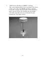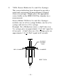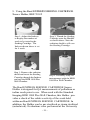
1
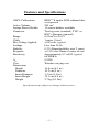
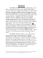
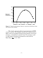
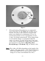
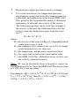
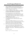
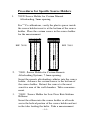
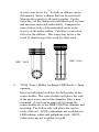
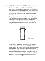
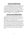
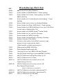
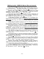
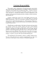
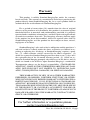
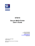
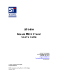
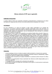
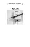
SeeDOS Product User Manual
HDR 1000 Plus
Ionization Chamber
Table of Contents
General Precautions ...................................................... 2
Features and Specifications .......................................... 3
General Procedures for Medical Measurements ........... 4
Overview ...................................................................... 6
Operation ...................................................................... 8
192
Procedures for Calibration of HDR Ir sources ........ 10
Procedures for Calibration and Measurement
of LDR Brachytherapy Sources ............................... 13
Procedures for Specific Source Holders ..................... 14
Calibration of HDR 1000 Plus ................................... 25
Constancy Check of HDR 1000 Plus ......................... 25
Maintenance................................................................ 26
Service ........................................................................ 26
Brachytherapy Parts List ............................................ 27
Bibliography; HDR Iridium Measurements ............... 28
Customer Responsibility ............................................ 29
Warranty ..................................................................... 30
General Precautions
WARNING: Electrical shock hazard when connected to 300 V
bias supply. Do not remove cover.
CAUTION: Proper use of this device depends on careful
reading of all instructions and labels.
CAUTION: This device should never be submerged to clean or
scrubbed with an abrasive cleaner.
CAUTION: Do not drop, mishandle, or disassemble unit since
it may result in change of calibration factor. Refer
all servicing to qualified individuals.
CAUTION: Do not sharply bend triax cable. Damage to the
cable may result in high leakage currents.
CAUTION: Insure source freely moves within secured catheter.
Proper location of source is necessary to assure
proper calibration.
–2–
Features and Specifications
ADCL Calibrations
Active Volume
Isotope Source Holder
Connector
Range
Cable
Bias Voltage Applied
Leakage
Stability
Response
Sensitivity
Aion
Case
Dimensions
Height
Diameter
Insert Diameter
Insert Height
Weight
HDR 192Ir and/or LDR radionuclides
as requested
245 cm3
11 source holders available
Two lug triax (standard), TNC, or
BNC + Banana (optional)
0.01 mCi to 20 Ci
1 meter (3 feet)
±300 volts, typical
Less than 50 fA
0.2% (Reproducibility over 2 years)
± 0.5% over 25mm at center of axis
Approximately 8.7 nA/Ci, typical
for HDR Ir
0.9996
Wooden carrying case
15.6 cm (6.1 in.)
10.2 cm (4 in.)
3.5 cm (1.4 in.)
12.1 cm (4.8 in.)
2.7 kg (6.1 lbs)
Specifications are subject to change without notice.
–3–
General Procedures for Medical Measurements
The following procedures should be used any time that
measurements are to be made with an ionization chamber
and electrometer system. This applies only to the setup of
the ionization chamber and electrometer, not to the setup of
the ionization source.
1.
With nothing connected to the input jack of the
electrometer, turn the power on and wait at least 10
minutes for warm up.
2.
Verify the leakage of the electrometer is within the
manufacturer’s stated acceptable limits.
3.
Connect the ionization chamber to the electrometer
and apply 100% voltage bias.
4.
Allow the electrometer and the ionization chamber
system at least 10 minutes to stabilize,making certain
that all cabling is lying flat and unkinked.
5.
Verify the leakage of the ionization chamber is within
the manufacturer’s stated acceptable limits.
6.
Some electrometers, such as the Standard Imaging
MAX 4000 Electrometer, allow the user to zero the
device at any time. If desired, perform this system
zeroing now.
7.
Check the system leakage. Take a reading without
exposing the chamber to radiation. This reading
should be less than 0.1% of the final signal expected.
8.
Measure the atmospheric temperature and pressure.
–4–
9.
Turn on or insert the radiation source(s) and take at
least 3 measurements. Generally the measurments
should not be moving in only one direction (i.e. three
readings that continue to drop and hence may not yet
be stabilized).
10.
Analyze the data taking into account the average of
the readings, system leakage, temperature/pressure
corrections, calibration factors and any other
appropriate corrections to be made. Keep in mind
that the calibration factor consists of the electrometer
calibration factor and the ionization chamber calibration factor.
11.
When all measurements are completed, set bias
voltage to 0VDC, turn off the electrometer and
disconnect the ionization chamber.
–5–
Overview
The Standard Imaging HDR 1000 Plus Ionization
chamber is a well-type chamber. It is specifically designed
for use with both the brachytherapy high-dose-rate (HDR)
remote afterloading irradiators and low-dose-rate (LDR)
brachytherapy sources, with the appropriate calibration. It
is recommended that the chamber be calibrated every two
years as is standard practice for other ionization chambers.
Initially, the calibration factor is given in the calibration
report from the Accredited Dosimetry Calibration Laboratory (ADCL). The appendix provided with the calibration
report discusses the calibration factors in greater detail.
Calibration factors should be obtained from an ADCL for
each brachytherapy source that is being measured. The
ionization current expected from the HDR 1000 Plus is
approximately 8.7 nA/Ci for HDR brachytherapy sources.
Thus, the measurement of all brachytherapy sources requires an electrometer with a calibrated scale for measuring
currents in the range from 10-8A to 10-7A. Alternatively, a
calibrated charge scale may be used with timed runs. If
integral charge techniques are used with the time determined by the HDR irradiator timer, the contribution from
the source transit-time should be taken into account.
The HDR afterloading technique minimizes potential radiation exposure to medical personnel and permits
brachytherapy treatments in a shorter time period. Calibration of all brachytherapy sources with ionization chambers
is important. When a brachytherapy source with a high
dose rate is used, it is imperative that there be an accurate
and reliable calibration of the source strength by means of a
suitable chamber, such as the HDR 1000 Plus. The initial
activity of the 192Ir sources for high dose rate
–6–
brachytherapy applications is typically around 10
curies (Ci), or 370 gigabecquerels (GBq). The half life of
192
Ir is 73.83 days. Therefore, frequent (usually quarterly)
source replacements are required. These sources must be
calibrated when placed in use and should be checked
periodically during use. Suppliers of sources usually
provide calibration certificates that can have an uncertainty
of ±10%, necessitating an independent calibration for
better accuracy. This point is addressed in the article
published in Int. J. Radiat. Oncol. Biol. Phys. 24: 167-170
(1992) and Chapter 5 of High Dose Rate Brachytherapy:
A Textbook, ed. S. Nag. Calibration methods for HDR
sources using methods other than the HDR 1000 Plus welltype chamber can be complicated, time-consuming and
prone to error. The HDR 1000 Plus is convenient for
frequent use, since the time required for calibration is only
a fraction of that required for thimble ionization chamber
techniques. A recommended calibration technique is given
in Med. Phys. 18: 462-467 (1991).
Please note that the factors that are used in the
calibration of these chambers are the most current, and in
some cases, may be different than those used in HDR
treatment planning computers. This difference, if present,
should be accounted for during your treatment planning
activities. To avoid confusion, the American Association of
Physicists in Medicine has recommended that air kerma
calibrations be used for brachytherapy sources (AAPM
Reports No. 41 and 21) instead of source activity.
–7–
Operation
The HDR 1000 Plus ionization chamber has a vent
hole to maintain the internal air at ambient atmospheric
pressure. Thus, the readings obtained must be corrected for
ambient temperature and pressure to the temperature and
pressure of calibration (22o C and 760 mm Hg) at “normal”
relative humidity (50% ± 25%non-condensing) in the usual
accepted manner. The HDR 1000 Plus has available
different inserts for HDR measurements, including a
quality assurance (QA) insert. Note that the QA insert can
provide information for source positioning verification,
timer accuracy and consistency of source activity for HDR
applications. This tool is described in Med. Phys. 22:
April 1995 and in a separate instruction manual. Contact
Standard Imaging for further information. The inserts are
designed so that the center of all sources are located at the
most sensitive spot of the chamber. Figure 1 shows a
typical axial response curve for the HDR 1000 Plus. There
is only a 0.1% decrease in sensitivity within + 5 mm of
center.
The HDR 1000 Plus utilizes a conventional triax
connector and cable to be connected to a suitable
electrometer. A bias of 300 volts must be applied to the
electrometer low-impedance connection relative to chassis
ground. The voltage polarity effect is less than 0.1%. If
desired, a second bias level of 150 volts can also be used to
determine the ionic recombination loss at 300 V. 1 The
ionic recombination loss is less than 0.05% and thus can be
considered negligible. The chamber calibration refers to
the positive and negative voltage average.
1 The equation used is A
ion = 4/3 - (Q1/3Q2), where Q1 is the charge or current measured at 300 V
and Q2 is the charge or current measured at 150 V. See Med. Phys. 11: 714 (1984).
–8–
101
100
99
Percent
Response
98
97
96
20
30
40
50
60
70
80
Distance from Bottom of Chamber (mm)
Figure 1: Typical axial response shown as a percent with distance from
the bottom of the chamber.
The step by step procedure for measurement of HDR
sources is given. The chamber should not be placed near a
high scatter environment during measurements for the best
accuracy; it should be located at least 25 cm from a wall
or other high-scattering environment as described in
Med. Phys. 19: 1311, 1992.
–9–
Procedures for calibration of HDR 192Ir sources
1.
Place the HDR 1000 Plus chamber in the same room
as the HDR unit for at least 30 minutes before the
measurement to allow it to equilibrate to ambient
temperature and pressure.
2.
Connect the HDR 1000 Plus chamber to a suitable
electrometer, such as the MAX 4000 from Standard
Imaging, and apply 300 V bias voltage. Allow the
system to stabilize for at least 10 min.
3.
Connect a catheter, such as the endobronchial, French
6 blue catheter to HDR irradiator.
4.
Align the black dot on the well insert with the punch
mark on the body of the chamber (See Figure 2).
5.
Insert catheter end to bottom of chamber source
holding insert. The dead space at the catheter end
192
must be known, so that the center of the Ir source
can be positioned at the most sensitive position of the
chamber. See Figure 1 for a typical axial response
curve for the HDR 1000 Plus. Normally the most
sensitive spot for the HDR 1000 Plus chamber is
between 50 and 53 mm from the bottom of the source
tube. This point is provided in the calibration report
for each chamber. The chamber sensitivity decreases
by approximately 0.1% when the source is moved up
or down by 5 mm from that position.
6.
Secure the catheter with the knurled catheter holding
device.
– 10 –
Black
dot
Punch mark
Figure 2
7.
After performing all manufacturer recommended
safety procedures for the HDR after-loading device,
192
run the Ir source to the radiation sensitive axial
point of the chamber for a minimum of 20 sec for
current measurement or for a reproducible set time
(1 min.) for charge measurement. If the charge mode
is used and the charge is accumulated while the
source is in transit, account for the transit time error
of the source by making the standard timer end effect
measurements as described in High Dose Rate
Brachytherapy: A Textbook, Nag, ed. Futura, 1994.
Note: This value will differ depending on the length of the
catheter. The timer feature of the Standard Imaging
MAX 4000 (REF 90015) can be used to collect
charge for set times and eliminate this effect.
– 11 –
8.
Read and record the measured current or charge.
9.
Use correction factors for temperature/pressure,
electrometer correction factor (electrometer must be
calibrated) and calibration factor for the HDR 1000
Plus given by the Accredited Dosimetry Calibration
Laboratory to calculate the activity of the source.
The following equation can be used (for example if
the activity is desired, the calibration factor for the
activity from the calibration report would be used
for C)
B=R*F*E*C
where:
B = the Activity of the source in Bq or Ci depending which
calibration factor is used.
R = the reading in A (if current scale) or in C/s (if charge
scale measured for a set time in s)
F = the temperature and pressure correction factor
E = the correction factor for the electrometer scale
C = the HDR 1000 Plus calibration factor (in this case
the activity calibration factor)
Note: “B” can be divided by Aion if desired to correct for
recombination effects. Since the HDR 1000 Plus has an Aion
of 1.000, this is not necessary.
For example, if R = 5.435 x 10⁻⁸ A, F = 1.021, E = 0.999 and
C = 1.271 x 10⁸ Ci/A, then B = (5.435 x 10-8) * (1.021) *
(0.999) * (1.271 x 108) = 7.05 Ci
– 12 –
Procedures for Calibration and
Measurement of LDR Brachytherapy Sources
1.
Place the HDR 1000 Plus Brachytherapy Well
Chamber in the same room the measurements are to
be done in for at least 30 minutes to equilibrate to
ambient temperature and pressure
2.
Connect the HDR 1000 Plus chamber to a suitable
electrometer and supply 300 V bias voltage. Allow
system to stabilize for at least 10 minutes.
3.
Insert the appropriate source holder for the
brachytherapy source to be measured into the chamber. Align the black dot on the well insert with the
punch mark on the body of the chamber (see Figure 2
in HDR iridium procedure).
4.
Using appropriate safety procedures for
brachytherapy sources, insert the source into the
source tube.
5.
Measure the LDR brachytherapy source for a minimum of 20 seconds for current measurements, or for a
reproducible set time for charge measurements.
6.
Read and record the measured current or charge.
7.
Use correction factor for temperature/pressure, electrometer correction factor (electrometer must be
calibrated) and isotope calibration factor to calculate
the activity of the source. The following equation can
be used
B=R*F*E*C
Refer to step 9 on the previous page.
– 13 –
Procedures for Specific Source Holders
1.
70020 Source Holder for Cesium Manual
Afterloading, 5mm opening.
137
For Cs calibrations, verify the plastic spacer inside
the source holder insert is at the bottom of the source
holder. Place the cesium source in the source holder
for the measurement.
REF 70020
2.
REF 70003
70003 Source Holder for Cesium Remote
Afterloading Systems, 7.1mm opening.
Insert the remote afterloading catheter into the source
holder. Advance the cesium source to the bottom of
the source holder. Retract the source to the most
sensitive area of the well chamber. Take a measurement.
3.
70009 Source Holder for Low Dose Rate Iridium
Ribbons
Insert the ribbon into the source holder so all seeds
are in the helical portion of the source holder and not
in the tube feeding the helix. Take a measurement
– 14 –
192
A correction factor for Ir seeds in ribbons can be
determined. Select a ribbon that can be sacrificed.
Measure the signal for all seeds together. On the
same day, cut the ribbon into individual seed sections
and measure each seed individually. Compare the
sum of the activity of the individual seeds to the
activity of the entire ribbon. Calculate a correction
factor for the ribbons. This correction factor is the
result of shadowing of the seeds by other seeds.
REF 70016
REF 70009
4.
70016 Source Holder for Single LDR Seeds, 1.2mm
opening.
Insert an individual seed into the Teflon tube of the
source holder. The source holder will place the seed
at the most active area of the chamber. Take a measurement. A seed can be removed by taking the
source holder out of the HDR 1000 Plus chamber and
inverting. The Teflon tube will allow the seed to
easily slide out. ADCL calibrations are available for
LDR iridium, iodine and palladium seeds. ADCL
calibrations are not available for gold.
– 15 –
5.
70022 Source Holder for LDR Seed Batch Assay
The Source Holder for LDR Seed Batch Assay,
REF 70022, is designed to hold up to 500 of the low
dose rate iodine or palladium seeds. The seeds to be
measured are positioned at the most sensitive position
on axis of the HDR 1000 Plus Brachytherapy Ion
Chamber.
The purpose of this source holder is to enable physicists to sample a subset, typically 10%, of the large
numbers of seeds often received for treatment of
cancer. For example, if several treatments for prostate cancer are imminent, 50 to 200 seeds may be
used per case.
REF 70022
To measure a number of seeds, place the desired
number in the Source Holder for LDR Seed Batch
Assay. Place the source holder in the HDR 1000 Plus
Ion Chamber. The seeds are centered at the most
sensitive part of the chamber. A reading can be made
with any standard electrometer. For consistency of
measurements, and to save time, the Standard Imaging MAX 4000 Electrometer can be set to collect
– 16 –
charge for a user defined amount of time.
An explanation of how to perform sample measurements is explained very well in the reference “Verifi125
103
cation of manufacturer-supplied I and Pd airkerma strengths.” Mellenberg and Kline; Medical
Physics. 22(9):1495-1497, 1995. A thorough review
of this article is recommended.
Correction factors for varying numbers of seeds need
to be determined for either iodine or palladium,
depending on which isotope is used. This is due to
the self absorption of the seeds in the source holder.
Once determined these factors should remain constant. Thereafter a set number of seeds, i.e. 25, 50,
100, can be measured.
References
125
103
1. “Verification of manufacturer-supplied I and Pd airkerma strengths”. Mellenberg & Kline; Medical
Physics. 22(9):1495-1497, 1995.
2. “Comprehensive QA for radiation oncology: Report of
AAPM Radiation Therapy Committee Task Group
40”. Medical Physics. 21(4):581-618, 1994.
– 17 –
6.
70023 Source Holder for RAPID Strand
Seeds
TM
Iodine
The source holder for RAPID Strand Iodine Seeds is
designed for QA measurements of the RAPID Strand
6711 Iodine Seeds prior to use. This insert works
with the Standard Imaging HDR 1000 Plus
Brachytherapy Well Chamber. The RAPID Strand
Source Holder is constructed to simultaneously
measure five seeds at one end of the RAPID Strand
while the RAPID Strand remains in the spacing jig.
The spacing jig is then inverted in the source holder
and the five seeds at the other end are measured. This
provides a QA check of the relative activity of the
five seeds on each end of the RAPID Strand.
RAPID Strand™
REF 70023
A RAPID Strand containing 10 iodine seeds was
obtained and an extensive evaluation was performed
with the HDR 1000 Plus and the RAPID Strand
Source Holder 70023. Following the evaluation,
individual seeds of the RAPID Strand were cut from
the strand and individually calibrated. These measurements were compared to the initial, collective
– 18 –
seed measurements of the intact RAPID Strand in
Source Holder 70023 to obtain a correction factor.
The correction factor was found to be approximately
1.15 times the 6711 iodine calibration factor from the
University of Wisconsin Accredited Dosimetry
Calibration Laboratory.
The RAPID Strand Source Holder, REF 70023, can
be gas sterilized or steam sterilized (autoclaved).
To measure a RAPID Strand of iodine seeds, place
the spacing jig, with the RAPID Strand in place, into
the source holder. There is a plastic key on the
bottom of the lead shielding to guide the spacing jig
so the seeds are in the center of the well chamber.
There is no measurable rotational dependence.
Record the measured activity. Invert the RAPID
Strand and take another measurement.
A formula can be used to determine the average seed
activity as a QA measurement of the sum of the
activity of 5 seeds.
Seed Activity = R * CF * CT/P * EF
N
Seed Activity = average seed activity as a QA measurement
R = reading
CF(correction factor) = defined as approximately
1.15 times the ADCL 6711 iodine calibration factor
N = number of seeds
CT/P = correction for temperature and pressure
EF = electrometer correction factor
– 19 –
For Example:
If you receive a strand with a nominal or average
2 -1
activity of 0.3µGym h per seed, the typical 5 seeds
were measured, and the iodine calibration factor of
11
2 -1 -1
2.6 x 10 µGym h A is used.
Assume:
-11
R = 0.4957 x 10 A
11
CF = (1.15) (2.6 x 10 )
N = 5
C
= 1.014
T/P
EF = 0.998
Seed Activity =
-11
11
(0.4957 x 10 A)(2.6 x 10 ) (1.15) (1.014) (0.998)
5
2 -1
Seed Activity = 0.3µGym h
This average seed activity, as a QA measurement, can
be compared to your expected RAPID Strand activity.
Note, this is a QA measurement assuming the five
seeds are the same activity.
– 20 –
7.
70024 Source Holder for MICK® Cartridge
This source holder allows for a constancy QA check
of the seeds. After the MICK cartridge is loaded,
insert the cartridge into the holder so that the black
part is on top. Screw the cartidge into the holder
and make sure the seeds are not blocked by the
metal posts. See figure below.
– 21 –
8.
70026 Source Holder for 5cc and 10cc Syringes
This source holder has been designed to provide a
quick and convenient QA measurement of liquid
sources in syringes. Simply place the appropriate
source holder in the HDR 1000 Plus chamber for a
measurement.
Source Holder 70026 for 5cc and 10cc Syringes,
includes one set of two syringe holders, one for a 5cc
syringe and one for a 10cc syringe.
Example: For a Medastron source, a 4mCi dose in a
5cc syringe gives an approximate 3.3+0.1nC signal in
60 seconds. A 4mCi dose in a 10cc syringe gives an
approximate 3.03 +0.05nC signal in 60 seconds.
SOURCE
HOLDER
70026
WELL CHAMBER
WELL CHAMBER
REF 70026
– 22 –
9. Using the Bard EXPRESS SEEDING CARTRIDGE
Source Holder, REF 70032
Step 2: Thread the Seeding
Cartridge onto the Handler
as shown above. Note the
radiation shield is still over
the Seeding Cartridge.
Step 1: Adjust the Indexer
to display the number of
seeds to be tested in the
Seeding Cartridge. The
Indexer shown above is set
for 4 seeds.
Step 3: Remove the radiation
shield and insert the Seeding
Cartridge through the Indexer
and into the HDR 1000 Plus
Well Chamber.
Step 4: Assembly ready for
measurement with the HDR
1000 Plus Well Chamber.
The Bard EXPRESS SEEDING CARTRIDGE Source
Holder is designed for QA measurements of palladium or
iodine seeds prior to use. When used with the Standard
Imaging HDR 1000 Plus Well Chamber, this Holder provides a check of the relative activity of the seeds held
within an Bard EXPRESS SEEDING CARTRIDGE. In
addition, the Holder can be gas sterilized or steam sterilized
(autoclaved). Evaluations were performed at the University
– 23 –
of Wisconsin ADCL and K&S Associates ADCL which
compared the collective seed measurements from this
Source Holder to the sum of the individual seeds, as measured with a Standard Imaging Single Seed Source Holder,
REF 70016. These measurements revealed the ratios or
“correction factors” for palladium and iodine to be approximately 1.5 times and 1.2 times, respectively, the single seed
calibration factors from the ADCLs.
103
Sources tested were Theragenics Theraseed (Pd ) and
SourceTech Medical STM 1251 (I125).
The following formula can be used to determine the
average seed activity as a QA measurement of the sum of
the activity of seeds. Note that this measurement assumes
all seeds are the same activity.
Seed Activity = (R * CF * CT/P * EF ) / N where
R = reading, CF (correction factor) = 1.5 times the ADCL Pd103 cal
factor or 1.2 times the ADCL I125 cal factor C = correction for
T/P
temperature and pressure, EF = electrometer correction factor
and N = number of seeds, two (2) through six (6).
For Example:
103
You receive a Seeding Cartridge with 5 Pd seeds of nominal activity
2 -1
of 1.0 mGym h per seed, the cartridge is measured with the Source
11
Holder (REF 70032) and the palladium calibration factor 2.6 x 10
2 -1
mGym h A is used.
11
Assume: R = 1.272 x 10⁻¹¹A, CF = (1.5) * (2.6 x 10 ), CT/P = 1.014,
EF = 0.998 and N = 5.
Then:
11
Seed Activity = ((1.272 x 10-11) * (1.5) * (2.6 x 10 ) * (1.014) *
2 -1
(0.998))/5 = 1.0 mGym h
– 24 –
Calibration of HDR 1000 Plus
As is standard practice for other ion chambers, it is
recommended that the HDR 1000 Plus be calibrated every
2 years. This calibration should be performed by an Accredited Dosimetry Calibration Laboratory. Standard
Imaging offers calibrations from the University of Wisconsin Accredited Dosimetry Calibration Laboratory. You
need only one purchase order to cover calibrations, shipping and handling, and service. Standard Imaging hand
carries all instruments to and from the ADCL.
Constancy Check of HDR 1000 Plus
Regular constancy checks should be performed by
using a procedure such as the following. The source
holding insert may be removed to allow the stability of the
HDR 1000 Plus to be checked by means of a constancy
check source, e.g. using a low dose rate 137Cs
brachytherapy source with the insert in place or a 90Sr beta
source. Alternatively, the stability can be monitored with
the use of an external 60Co beam. This value should be
obtained upon receipt of the chamber and monitored for
consistency thereafter. Either place the chamber in the 60Co
beam at a known distance with a standard field, such as 10
cm x 10 cm, or place the 90Sr or 137Cs source in a reproducible position and take a current reading. A graph of the
response corrected for decay should remain within +/0.5%.
– 25 –
Maintenance
Exterior cleaning of the device can be done with a soft
brush and a cloth. Gently brush all surfaces to remove dirt
and dust. Remove any remaining dirt with a cloth slightly
dampened with a solution of mild detergent and water or a
liquid disinfecting agent. Be especially careful that this is
an external cleaning only and do not permit any liquid to
seep into the HDR 1000 Plus in any manner during cleaning.
Service
There are no serviceable parts on the HDR 1000
Plus. If the HDR 1000 Plus is disassembled, the calibration
factor will become invalid and necessitate recalibration.
Also, the warranty will become void if the HDR 1000 Plus
is disassembled. If the triax connector and external cable
are modified, the value of the leakage may be affected.
Notice:
We welcome your evaluation of this manual. Your
comments and suggestions help us improve
our publications.
– 26 –
REF
90008
70010
70020
70003
70009
70016
70022
70023
70026
70024
70032
70008
70004
70007
76004
50004
70025
80010
80020
80025-A
80025-B
80040-A
80040-B
80035
Brachytherapy Parts List
HDR 1000 PLUS Well Chamber
Source holder for HDR Iridium, 2.2mm opening
Source holder for Cesium, 5mm opening, for 90008
HDR 1000 Plus
Source holder for Cesium Remote Afterloading, 7.1 mm
opening
Source holder for low dose rate Iridium Ribbons
Source holder for Single LDR Seeds, 1.2mm opening
Source holder for LDR Seed Batch Assay, up to 500 Pd or
I seeds and for Iridium Wire Coil
Source holder for RAPID StrandTM Iodine Seeds
Source holder for 5cc and 10cc Syringes
Source holder for MICK Cartridge
Source holder for Bard Express Seeding Cartridge
Quality Assurance Tool Insert
10 meter cable with tri-axial BNC connectors and
protective caps connected by chains.
(Other lengths available upon request.)
Wall mount for HDR 1000 Plus
Tube/Standoff Replacement Kit
Carrying Case for any HDR 1000 Ion Chamber
One Inch thick lead ring to surround HDR 1000 Plus
ADCL Calibration for High Dose Rate Ir-192
ADCL Calibration for Cesium
ADCL Calibration for low dose rate Ir-192,
Alpha-Omega Services
ADCL Calibration for low dose rate Ir-192,
Best Medical International
Other Calibrations available
ADCL Calibration for Iodine, Amersham 6702
ADCL Calibration for Iodine, Amersham 6711
ADCL Calibration for Palladium
– 27 –
Bibliography; HDR Iridium Measurements
Calibration of 192Ir High Dose Rate Afterloading Systems,
Goetsch, Attix, Pearson, Thomadsen, Med. Phys. 18: 462-467, 1991.
Thermal and Scatter Effects on Radiation Sensitivity of Well
Chambers used for HDR 192Ir Calibrations, Podgorsak, DeWerd,
Thomadsen, Paliwal, Med. Phys. 19: 1311-1314, 1992.
A New Re-entrant Ionization Chamber for the Calibration of
192Ir High Dose Rate Sources, Goetsch, Attix, DeWerd, Thomadsen,
Int. J. Radiation Oncology Biol. Phys. 24: 167-170 1992.
“Calibration Principles and Techniques,” L. A. DeWerd, G.A.
Ezzell and J.F. Williamson, Chapter 5 of High Dose Rate Brachytherapy:
A Textbook, Subir Nag, (ed.) Futura Publishing Company, Inc., Armonk,
NY (1994).
“Calibration & Quality Assurance: I,” G.A. Ezzell, J. Hicks and
L.A. DeWerd, Chapter 54, pp. 233-236 in International Brachytherapy,
Nucletron International B. V. publisher (1992).
“Radiation Sensitivity of Well Chambers for HDR Iridium-192
Calibrations,” M. B. Podgorsak, L. A. DeWerd, B. R. Thomadsen & B.
R. Paliwal, Chapter 72, pp. 311-314 in International Brachytherapy,
Nucletron International B. V. publisher (1992).
“The Half-life of high dose rate Ir-192 sources,” Matthew B.
Podgorsak, Larry A. DeWerd, and Bhudatt Paliwal, Med Phys. 20: (4)
1257-1259 (1993).
“Evaluation of new re-entrant ionization chambers for high dose
rate brachytherapy calibrations,” Ezzell, Endocurietherapy/Hyperthermia Oncology 9: 233-238, 1993.
“Specification of Brachytherapy Source Strength, Report of Task
Group 32,” American Association of Physicists in Medicine, AAPM Report No. 21, (1987). New York: American Institute of Physics.
“Remote Afterloading Technology, Report of Task Group 41”
American Association of Physicists in Medicine, AAPM Report No. 41,
(1993). New York: American Institute of Physics.
“Clinical implementation of AAPM Task Group 32 recommendations on brachytherapy source strength specifications,” Williamson,
J.F. and Nath, R., (1991). Med. Phys. 18: 439-448.
– 28 –
Customer Responsibility
This product and its components will perform properly and reliably
only when operated and maintained in accordance with the instructions
contained in this manual and accompanying labels. A defective device
should not be used. Parts which may be broken or missing or are clearly
worn, distorted or contaminated should be replaced immediately with
genuine replacement parts manufactured by or made available from Standard Imaging Inc.
Caution: Federal law in the U.S.A. and Canada restricts the sale,
distribution, or use of this device to, by, or on the order of a licensed
medical practitioner. The use of this device should be restricted to the
supervision of a qualified medical physicist. Measurement of high activity radioactive sources is potentially hazardous and should be performed
by qualified personnel.
Should repair or replacement of this device become necessary after
the warranty period, the customer should seek advice from Standard
Imaging Inc. prior to such repair or replacement. If this device is in need
of repair, it should not be used until all repairs have been made and the
product is functioning properly and ready for use. After repair, the chamber may need to be calibrated. The owner of this device has sole responsibility for any malfunction resulting from abuse, improper use or maintenance, or repair by anyone other than Standard Imaging Inc.
The information in this manual is subject to change without notice.
No part of this manual may be copied or reproduced in any form or by
any means without prior written consent of Standard Imaging Inc.
– 29 –
Warranty
This product is sold by Standard Imaging Inc. under the warranty
herein set forth. The warranty is extended only to the buyer purchasing the
product directly from Standard Imaging Inc. or as a new product from an
authorized dealer or distributor of Standard Imaging Inc.
For a period of twenty-four (24) months from the date of original
delivery to the purchaser or a distributor, this product is warranted against
functional defects in materials and workmanship, provided it is properly
operated under conditions of normal use, and that repairs and replacements
are made in accordance herewith. The foregoing warranty shall not apply
if the product has been disassembled, altered or repaired other than by
Standard Imaging Inc. or if the product has been subject to abuse, misuse,
negligence or accident.
Standard Imaging’s sole and exclusive obligation and the purchaser’s
sole and exclusive remedy under the above warranties are limited to repairing or replacing free of charge, at Standard Imaging’s option, a product: (1) which contains a defect covered by the above warranties; (2)
which are reported to Standard Imaging not later than seven (7) days after
the expiration date of the 24-month warranty period; (3) which are returned to Standard Imaging promptly after discovery of the defect; and (4)
which are found to be defective upon Standard Imaging’s examination.
Transportation charges are the buyer’s responsibility. STANDARD IMAGING INC. SHALL NOT BE OTHERWISE LIABLE FOR ANY DAMAGES, INCLUDING BUT NOT LIMITED TO, INCIDENTAL DAMAGES, CONSEQUENTIAL DAMAGES, OR SPECIAL DAMAGES.
THIS WARRANTY IS IN LIEU OF ALL OTHER WARRANTIES,
EXPRESSED OR IMPLIED, WHETHER STATUTORY OR OTHERWISE, INCLUDING ANY IMPLIED WARRANTY OF FITNESS FOR A
PARTICULAR PURPOSE. IN NO EVENT SHALL STANDARD IMAGING INC. BE LIABLE FOR ANY INCIDENTAL OR CONSEQUENTIAL DAMAGES RESULTING FROM THE USE, MISUSE OR ABUSE
OF THE PRODUCT OR CAUSED BY ANY DEFECT, FAILURE OR
MALFUNCTION OF THE PRODUCT, WHETHER A CLAIM OF SUCH
DAMAGE IS BASED UPON THE WARRANTY, CONTRACT, NEGLIGENCE, OR OTHERWISE.
© 2002 Standard Imaging Inc.
Distributed
by SeeDOS Ltd
7601 Murphy
Drive
Middleton, information
WI 53562
Phone: (608) 831-0025
For further
or a quotation
please
Fax:
(608) 831-2202
contact [email protected]
Doc. No. 80026-06, 05-09-02, 30 pgs.