1
User’s
Manual
Fiber-optic FA-bus Module
Fiber-optic FA-bus Type 2 Module
FA-bus Type 2 Module
IM 34M06H45-01E
Applicable Modules:
Model Code
Model Name
F3LR01-0N
Fiber-optic FA-bus Module
F3LR02-0N
Fiber-optic FA-bus Type 2 Module
F3LR02-1W
FA-bus Type 2 Module
IM 34M06H45-01E
Yokogawa Electric Corporation
5th Edition
Blank Page
i
Applicable Product:
Range-free Controller FA-M3
-
Model
: F3LR01-0N
Model Name : Fiber-optic FA-bus Module
-
Model
-
Model Name : Fiber-optic FA-bus Type 2 Module
-
Model
: F3LR02-1W
Model Name : FA-bus Type 2 Module
: F3LR02-0N
The document number and document model code for this manual are given below.
Refer to the document number in all communications; also refer to the document
number and the document model code when purchasing additional copies of this
manual.
-
Document No.
: IM 34M06H45-01E
Document Model Code : DOCIM
Media No. IM 34M06H45-01E (CD) 5th Edition : Jan. 2012(AR)
All Rights Reserved Copyright © 2012 Yokogawa Electric Corporation
IM 34M06H45-01E
5th Edition : Jan. 2012-00
ii
Important
About This Manual
-
This Manual should be passed on to the end user.
Before using the controller, read this manual thoroughly to have a clear
understanding of the controller.
This manual explains the functions of this product, but there is no guarantee that
they will suit the particular purpose of the user.
Under absolutely no circumstances may the contents of this manual be transcribed
or copied, in part or in whole, without permission.
The contents of this manual are subject to change without prior notice.
Every effort has been made to ensure accuracy in the preparation of this manual.
However, should any errors or omissions come to the attention of the user, please
contact the nearest Yokogawa Electric representative or sales office.
Safety Precautions when Using/Maintaining the Product
-
The following safety symbols are used on the product as well as in this manual.
Danger. This symbol on the product indicates that the operator must follow the
instructions laid out in this user’s manual to avoid the risk of personnel injuries,
fatalities, or damage to the instrument. The manual describes what special care
the operator must exercise to prevent electrical shock or other dangers that may
result in injury or the loss of life.
Protective Ground Terminal. Before using the instrument, be sure to ground this
terminal.
Function Ground Terminal. Before using the instrument, be sure to ground this
terminal.
Alternating current. Indicates alternating current.
Direct current. Indicates direct current.
IM 34M06H45-01E
5th Edition : Jan. 2012-00
iii
The following symbols are used only in the user’s manual.
WARNING
Indicates a “Warning”.
Draws attention to information essential to prevent hardware damage, software
damage or system failure.
CAUTION
Indicates a “Caution”
Draws attention to information essential to the understanding of operation and
functions.
TIP
Indicates a “TIP”
Gives information that complements the present topic.
SEE ALSO
Indicates a “SEE ALSO” reference.
Identifies a source to which to refer.
-
-
-
-
For the protection and safe use of the product and the system controlled by it, be
sure to follow the instructions and precautions on safety stated in this manual
whenever handling the product. Take special note that if you handle the product in
a manner other than prescribed in these instructions, the protection feature of the
product may be damaged or impaired. In such cases, Yokogawa cannot guarantee
the quality, performance, function and safety of the product.
When installing protection and/or safety circuits such as lightning protection
devices and equipment for the product and control system as well as designing or
installing separate protection and/or safety circuits for fool-proof design and failsafe design of processes and lines using the product and the system controlled by
it, the user should implement it using devices and equipment, additional to this
product.
If component parts or consumable are to be replaced, be sure to use parts
specified by the company.
This product is not designed or manufactured to be used in critical applications
which directly affect or threaten human lives and safety — such as nuclear power
equipment, devices using radioactivity, railway facilities, aviation equipment, air
navigation facilities, aviation facilities or medical equipment. If so used, it is the
user’s responsibility to include in the system additional equipment and devices that
ensure personnel safety.
Do not attempt to modify the product.
Exemption from Responsibility
-
-
Yokogawa Electric Corporation (hereinafter simply referred to as Yokogawa
Electric) makes no warranties regarding the product except those stated in the
WARRANTY that is provided separately.
Yokogawa Electric assumes no liability to any party for any loss or damage, direct
or indirect, caused by the user or any unpredictable defect of the product.
IM 34M06H45-01E
5th Edition : Jan. 2012-00
iv
Software Supplied by the Company
-
Yokogawa Electric makes no other warranties expressed or implied except as
provided in its warranty clause for software supplied by the company.
Use the software with one computer only. You must purchase another copy of the
software for use with each additional computer.
Copying the software for any purposes other than backup is strictly prohibited.
Store the original media, such as floppy disks, that contain the software in a safe
place.
Reverse engineering, such as decompiling of the software, is strictly prohibited.
No portion of the software supplied by Yokogawa Electric may be transferred,
exchanged, or sublet or leased for use by any third party without prior permission
by Yokogawa Electric.
IM 34M06H45-01E
5th Edition : Jan. 2012-00
v
General Requirements for Using the FA-M3
Avoid installing the FA-M3 in the following locations:
-
-
Where the instrument will be exposed to direct sunlight, or where the operating
temperature exceeds the range 0C to 55C (32F to 131F).
Where the relative humidity is outside the range 10 to 90%, or where sudden
temperature changes may occur and cause condensation.
Where corrosive or flammable gases are present.
-
Where the instrument will be exposed to direct mechanical vibration or shock.
Where the instrument may be exposed to extreme levels of radioactivity.
-
Select an appropriate field wiring material:
-
USE COPPER CONDUCTORS ONLY.
Use copper conductors having temperature rating of minimum 75C for the field
wiring.
Securely tighten screws:
-
Securely tighten module mounting screws and terminal screws to avoid problems
such as faulty operation.
Tighten terminal block screws with the correct tightening torque as given in this
manual.
Securely lock connecting cables:
-
Securely lock the connectors of cables, and check them thoroughly before turning
on the power.
Interlock with emergency-stop circuitry using external relays:
-
Equipment incorporating the FA-M3 must be furnished with emergency-stop
circuitry that uses external relays. This circuitry should be set up to interlock
correctly with controller status (stop/run).
Low impedance grounding:
-
For safety reasons, connect the [FG] grounding terminal to a Japanese Industrial
Standards (JIS) Class D (earlier called Class 3) Ground. For compliance to CE
Marking, use braided or other wires that can ensure low impedance even at high
frequencies for grounding.
Configure and route cables with noise control considerations:
-
Perform installation and wiring that segregates system parts that may likely
become noise sources and system parts that are susceptible to noise. Segregation
can be achieved by measures such as segregating by distance, installing a filter or
segregating the grounding system.
Configure for CE Marking Conformance:
-
For compliance with CE Marking, perform installation and cable routing according
to the description on compliance to CE Marking in the “Hardware Manual”
(IM34M06C11-01E).
IM 34M06H45-01E
5th Edition : Jan. 2012-00
vi
Keep spare parts on hand:
-
Stock up on maintenance parts including spare modules, in advance.
Preventive maintenance (replacement of the module or its battery) is required for
using the module beyond 10 years. For enquiries on battery replacement service,
contact your nearest Yokogawa Electric representative or sales office. (The module
has a built-in lithium battery. Lithium batteries may exhibit voltage drop, and in rare
cases, electrolyte leakage after ten years.)
Discharge static electricity before operating the system:
-
Because static charge can accumulate in dry conditions, first touch grounded metal
to discharge any static electricity before touching the system.
Never use solvents such as paint thinner for cleaning:
-
Gently clean the surfaces of the FA-M3 with a cloth that has been soaked in water
or a neutral detergent and wringed.
Do not use volatile solvents such as benzine or paint thinner or chemicals for
cleaning, as they may cause deformity, discoloration, or malfunctioning.
Avoid storing the FA-M3 in places with high temperature or humidity:
-
-
Since the CPU module has a built-in battery, avoid storage in places with high
temperature or humidity.
Since the service life of the battery is drastically reduced by exposure to high
temperatures, take special care (storage temperature should be from –20C to
75C).
There is a built-in lithium battery in a CPU module and temperature control module
which serves as backup power supply for programs, device information and
configuration information. The service life of this battery is more than 10 years in
standby mode at room temperature. Take note that the service life of the battery
may be shortened when installed or stored at locations of extreme low or high
temperatures. Therefore, we recommend that modules with built-in batteries be
stored at room temperature.
Always turn off the power before installing or removing modules:
-
Failing to turn off the power supply when installing or removing modules, may
result in damage.
Do not touch components in the module:
-
In some modules you can remove the right-side cover and install ROM packs or
change switch settings. While doing this, do not touch any components on the
printed-circuit board, otherwise components may be damaged and modules may
fail to work.
Do not use unused terminals:
-
Do not connect wires to unused terminals on a terminal block or in a connector.
Doing so may adversely affect the functions of the module.
IM 34M06H45-01E
5th Edition : Jan. 2012-00
vii
Waste Electrical and Electronic Equipment
Waste Electrical and Electronic Equipment (WEEE), Directive 2002/96/EC
(This directive is only valid in the EU.)
This product complies with the WEEE Directive (2002/96/EC) marking requirement.
The following marking indicates that you must not discard this electrical/electronic
product in domestic household waste.
Product Category
With reference to the equipment types in the WEEE directive Annex 1, this product is
classified as a “Monitoring and Control instrumentation” product.
Do not dispose in domestic household waste.
When disposing products in the EU, contact your local Yokogawa Europe B. V. office.
How to Dispose of the Battery Used in This Product
The following description about the new Battery Directive 2006/66/EC is only valid in
the EU.
This product uses an embedded battery, which cannot be removed by a customer and
should be disposed of together with the product.
Do not dispose in domestic household waste.
When disposing products in the EU, contact your local Yokogawa Europe B. V. office.
Battery category: Lithium battery
Note: With reference to Annex II of the new Battery Directive 2006/66/EC, the above
symbol indicates obligatory separate collection.
IM 34M06H45-01E
5th Edition : Jan. 2012-00
viii
Introduction
Overview of the Manual
This manual describes the specifications of the Fiber-optic FA-bus Module, Fiber-optic
FA-bus Type 2 Module and FA-bus Type 2 Module, as well as how to send or receive
data using these modules.
These modules are used to control distributed I/O subunits installed at remote locations
(approximately 100 to 500 meters away).
For the Fiber-optic FA-bus Module and Fiber-optic FA-bus Type 2 Module, the use of
fiber-optic cables as communications lines provides noise immunity and allows highspeed communications.
Structure of the Manual
This manual consists of three parts as follows.
Part A: Fiber-optic FA-bus Module (F3LR01-0N),
Part B: Fiber-optic FA-bus Type 2 Module (F3LR02-0N), and
Part C: FA-bus Type 2 Module (F3LR02-1W).
Other User’s Manuals
The manuals to be read depend on the CPU module to be used.
You should read the latest versions of the following user manuals, as required.
F3SP71, F3SP76 functions
-
Sequence CPU Instruction Manual – Functions (for F3SP71-4N/4S, F3SP767N/7S) (IM34M06P15-01E)
Sequence CPU – Network Functions (for F3SP71-4N/4S, F3SP76-7N/7S)
(IM34M06P15-02E)
F3SP66, F3SP67 functions
-
Sequence CPU – Functions (for F3SP66-4S, F3SP67-6S) (IM34M06P14-01E)
Sequence CPU – Network Communication Functions (for F3SP66-4S, F3SP67-6S)
(IM34M06P14-02E)
F3SP22, F3SP28, F3SP38, F3SP53, F3SP58, or F3SP59 functions
-
Sequence CPU – Functions (for F3SP22-0S, F3SP28-3N/3S, F3SP38-6N/6S,
F3SP53-4H/4S, F3SP58-6H/6S, F3SP59-7S) (IM34M06P13-01E)
F3SP21, F3SP25, F3SP35, F3SP05, or F3SP08 functions
-
Sequence CPU – Functions (for F3SP21, F3SP25, and F3SP35)
(IM34M06P12-02E)
Instructions
-
Sequence CPU – Instructions (IM34M06P12-03E)
IM 34M06H45-01E
5th Edition : Jan. 2012-00
ix
Ladder programming
-
FA-M3 Programming Tool WideField3 (IM34M06Q16-01E, -02E, -03E, -04E)
FA-M3 Programming Tool WideField2 (IM34M06Q15-01E)
All sequence CPU modules
For information on the specifications*, configuration*, installation, wiring, trial
operation, maintenance and inspection of the FA-M3, or system-wide limitation of
module installation, refer to:
- Hardware Manual (IM34M06C11-01E)
*:
For information on the specifications of products other than power supply modules, base modules, I/O modules,
cables and terminal block units, refer to their relevant user’s manuals.
Documents on How to Lay Fiber-optic Cables
For details on laying of fiber-optic cables, read the following technical documents available
from Sumitomo Electric Industries, Ltd.
Name of Document
Document No.
Cabling Instructions for Fiber-optic Cords/Cables for Use with
the Sumi-Link DF Series
Technical Material No. 1769B
Fiber-optic Connector Assembling Tools Handling Instructions:
CAK- 1020 (for CF- 2011)
CAK- 0052 (for CF- 2071H)
Fiber-optic Technical Materials:
No. 1100 (for CF- 2011)
No. 1083 (for CF- 2071H)
Cabling Instructions for Fiber-optic Cables
Fiber-optic Connector Assembling Tool CAK-1020
(for CF-2011)
Fiber-optic Connector Assembling Tool CAK-0052
(for CF-2071H)
Technical Material No. 1769B
Fiber-optic Technical Materials
No. 1100
Fiber-optic Technical Materials
No. 1083
IM 34M06H45-01E
5th Edition : Jan. 2012-00
x
Copyrights and Trademarks
Copyrights
Copyrights of the programs and online manual included in this CD-ROM belong to
Yokogawa Electric Corporation.
This online manual may be printed but PDF security settings have been made to
prevent alteration of its contents.
This online manual may only be printed and used for the sole purpose of operating this
product. When using a printed copy of the online manual, pay attention to possible
inconsistencies with the latest version of the online manual. Ensure that the edition
agrees with the latest CD-ROM version.
Copying, passing, selling or distribution (including transferring over computer networks)
of the contents of the online manual, in part or in whole, to any third party, is strictly
prohibited. Registering or recording onto videotapes and other media is also prohibited
without expressed permission of Yokogawa Electric Corporation.
Trademarks
The trade names and company names referred to in this manual are either trademarks
or registered trademarks of their respective companies
IM 34M06H45-01E
5th Edition : Jan. 2012-00
TOC-1
FA-M3
Fiber-optic FA-bus, Fiber-optic FA-bus Type 2, FA-bus Type 2
Modules
IM 34M06H45-01E
5th Edition
CONTENTS
Applicable Product ....................................................................................i
Important ...................................................................................................ii
Introduction............................................................................................viii
Copyrights and Trademarks ....................................................................x
Part A: Fiber-optic FA-bus Module (F3LR01-0N)
A1. Overview .....................................................................................A1-1
A1.1
Features..................................................................................................A1-1
A1.2
Application Example .............................................................................A1-2
A2. Specifications .............................................................................A2-1
A2.1
Model and Suffix Codes........................................................................A2-1
A2.2
Function Specifications ........................................................................A2-1
A2.3
Operating Environment ........................................................................A2-1
A2.4
Components and Their Functions .......................................................A2-2
A2.5
External Dimensions .............................................................................A2-3
A3. System Configuration ................................................................A3-1
A3.1
Fiber-optic FA-bus System Configuration ..........................................A3-1
A3.1.1
Restrictions on System Configuration .....................................A3-1
A3.1.2
Connection Topology ...............................................................A3-1
A4. Pre-operation Setup and Cable Connection ............................A4-1
A4.1
Startup Procedure .................................................................................A4-1
A4.2
Setting Switches....................................................................................A4-2
A4.3
A4.2.1
Setting Unit Number Switch.....................................................A4-2
A4.2.2
Setting Condition Switches......................................................A4-3
Attaching and Detaching Modules.......................................................A4-4
A4.3.1
A4.4
A4.5
Attaching the Module...............................................................A4-4
A4.3.2
Detaching the Module..............................................................A4-4
A4.3.3
Attaching Modules in Intense Vibration Environments ............A4-5
A4.3.4
Installation Depth .....................................................................A4-5
Connecting Fiber-optic Cables ............................................................A4-6
A4.4.1
Cable Preparation....................................................................A4-6
A4.4.2
Attaching and Detaching Connectors ....................................A4-12
A4.4.3
Precautions When Connecting Fiber-optic Cables ...............A4-13
Pre-operation Checks .........................................................................A4-14
A4.5.1
Checking Transmission Loss.................................................A4-14
IM 34M06H45-01E
5th Edition : Jan. 2012-00
TOC-2
A4.5.2
A4.6
LED Checks...........................................................................A4-15
Precautions When Applying Power...................................................A4-16
A5. Accessing Modules in a Subunit ..............................................A5-1
A5.1
Slot Number in FA-M3 ...........................................................................A5-1
A6. I/O Refresh Time.........................................................................A6-1
A6.1
Estimating I/O Refresh Time.................................................................A6-1
A6.2
An Example of I/O Refresh Time Calculation .....................................A6-2
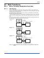
A7. RAS Functions............................................................................A7-1
A7.1
Error Location Detection Function ......................................................A7-1
A7.1.1
A7.2
LED Display.............................................................................A7-1
Shutdown Output on Transmission Channel Error Function ...........A7-2
A7.2.1
Overview of Shutdown Output Function..................................A7-2
A7.2.2
Shutdown Output of Subunit....................................................A7-2
A7.2.3
Procedure for Setting I/O Conditions.......................................A7-3
A7.2.3.1 Setting Condition Switches......................................A7-3
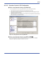
A7.2.3.2 DIO Setup in CPU Configuration.............................A7-4
A7.2.3.3 Operation Control in CPU Configuration .................A7-6
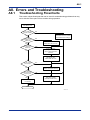
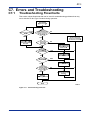
A8. Errors and Troubleshooting ......................................................A8-1
A8.1
Troubleshooting Flowcharts ................................................................A8-1
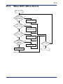
A8.2
When RDY LED is Not Lit......................................................................A8-2
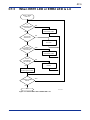
A8.3
When ERR LED is Lit.............................................................................A8-3
Index ............................................................................................Index A-1
Part B: Fiber-optic FA-bus Type 2 Module (F3LR02-0N)
B1. Overview .....................................................................................B1-1
B1.1
Features..................................................................................................B1-2
B2. Specifications .............................................................................B2-1
B2.1
Model and Suffix Codes........................................................................B2-1
B2.2
Function Specifications ........................................................................B2-1
B2.3
Operating Environment ........................................................................B2-1
B2.4
Components and Their Functions .......................................................B2-2
B2.5
External Dimensions .............................................................................B2-3
B3. Fiber-optic FA-bus Type 2 System Configuration ...................B3-1
B3.1
What Is a Substation? ...........................................................................B3-1
B3.2
Substation Configuration .....................................................................B3-2
B3.3
System Configuration and Slot Numbers ...........................................B3-3
B3.4
Restrictions on System Configuration................................................B3-6
B3.5
Connection Topology............................................................................B3-6
B3.6
System Configuration Design ............................................................B3-10
B3.7
Total Distance ......................................................................................B3-11
B3.8
Precautions When Changing Slot Number .......................................B3-12
IM 34M06H45-01E
5th Edition : Jan. 2012-00
TOC-3
B4. Pre-operation Setup and Cable Connection ............................B4-1
B4.1
Startup Procedure .................................................................................B4-1
B4.2
Setting Switches....................................................................................B4-2
B4.3
B4.4
B4.5
B4.6
B4.2.1
Setting Unit Number ................................................................B4-3
B4.2.2
B4.2.3
Setting Slot Number ................................................................B4-3
Enabling/Disabling Shutdown Output on
Transmission Channel Error Function .....................................B4-5
B4.2.4
Setting the Number of Ports ....................................................B4-5
B4.2.5
Setting Transmission Channel Configuration ..........................B4-6
B4.2.6
Setting Light Intensity ..............................................................B4-6
Attaching and Detaching Modules.......................................................B4-7
B4.3.1
Attaching the Module...............................................................B4-7
B4.3.2
Detaching the Module..............................................................B4-7
B4.3.3
Attaching Modules in Intense Vibration Environments ............B4-8
B4.3.4
Installation Depth .....................................................................B4-8
Connecting Fiber-optic Cables ............................................................B4-9
B4.4.1
Cable Preparation....................................................................B4-9
B4.4.2
Attaching and Detaching Connectors ....................................B4-15
B4.4.3
Precautions When Connecting Fiber-optic Cables ...............B4-16
B4.4.4
Connecting Fiber-optic Cables ..............................................B4-17
Pre-operation Checks .........................................................................B4-19
B4.5.1
Checking Transmission Loss.................................................B4-19
B4.5.2
LED Checks...........................................................................B4-20
Precautions When Applying Power...................................................B4-21
B5. I/O Refresh Time.........................................................................B5-1
B5.1
Estimating I/O Refresh Time.................................................................B5-1
B5.2
Example of I/O Refresh Time Calculation ...........................................B5-2
B6. RAS Functions of Fiber-optic FA-bus Type 2...........................B6-1
B6.1
B6.2
B6.3
B6.4
System Operation with Transmission Channel Error ........................B6-1
B6.1.1
Run or Stop System.................................................................B6-1
B6.1.2
B6.1.3
Causes of Transmission Channel Errors.................................B6-1
Defining System Operation (Run or Stop) in the Event of a
Transmission Channel Error....................................................B6-1
B6.1.4
Loop Switching ........................................................................B6-1
B6.1.5
Transmission Channel Loop-back Function ............................B6-4
Shutdown Output on Transmission Channel Error Function ...........B6-5
B6.2.1
Overview of Shutdown Output Function..................................B6-5
B6.2.2
Shutdown Output Function Setup ...........................................B6-5
Procedure for Setting Condition Switches .........................................B6-7
B6.3.1
Setting Condition Switches......................................................B6-7
B6.3.2
DIO Setup in CPU Configuration .............................................B6-8
B6.3.3
Operation Control in CPU Configuration ...............................B6-10
Error Location Detection Function ....................................................B6-11
B6.4.1
LED Display........................................................................... B6-11
B6.4.2
Logging of Transmission Channel Error Location .................B6-18
IM 34M06H45-01E
5th Edition : Jan. 2012-00
TOC-4
B7.
Errors and Troubleshooting .................................................................B7-1
B7.1
Troubleshooting Flowcharts.....................................................B7-1
B7.2
When RDY LED is Not Lit........................................................B7-2
B7.3
When ERR1 LED or ERR2 LED is Lit .....................................B7-3
Index ........................................................................................... Index B-1
Part C: FA-bus Type 2 Module (F3LR02-1W)
C1. Overview .....................................................................................C1-1
C1.1
Features..................................................................................................C1-2
C2. Specifications .............................................................................C2-1
C2.1
Model and Suffix Codes........................................................................C2-1
C2.2
Function Specifications ........................................................................C2-1
C2.3
Operating Environment ........................................................................C2-1
C2.4
Components and Their Functions .......................................................C2-2
C2.5
External Dimensions .............................................................................C2-3
C3. FA-bus Type 2 System Configuration.......................................C3-1
C3.1
System Elements and Terminology .....................................................C3-1
C3.2
System Configuration and Slot Numbers ...........................................C3-2
C3.3
Restrictions on System Configuration................................................C3-4
C3.4
Connection Topology............................................................................C3-5
C4.
Pre-operation Setup and Cable Connection.......................................C4-1
C4.1
Startup Procedure .................................................................................C4-1
C4.2
Setting Switches....................................................................................C4-2
C4.2.1
C4.2.2
C4.3
C4.2.3
Setting the Number of Ports ....................................................C4-4
C4.2.4
Setting Transmission Channel Configuration ..........................C4-5
Attaching and Detaching Modules.......................................................C4-6
C4.3.1
C4.4
Detaching the Module..............................................................C4-6
C4.3.3
Attaching Modules in Intense Vibration Environments ............C4-7
Connecting Transmission Cables........................................................C4-8
Cable Preparation....................................................................C4-8
C4.4.2
Recommended Cables ............................................................C4-8
C4.4.3
Wiring of Recommended Cables.............................................C4-9
C4.4.4
Usage Precautions for Fixed Cable (KM80)..........................C4-10
C4.4.5
Usage Precautions for Flexible Cable (KM81) ...................... C4-11
C4.4.6
Provided Connectors .............................................................C4-13
Pre-operation Checks .........................................................................C4-14
C4.5.1
C4.6
Attaching the Module...............................................................C4-6
C4.3.2
C4.4.1
C4.5
Setting Unit Number ................................................................C4-3
Enabling/Disabling Shutdown Output on Transmission
Channel Error ..........................................................................C4-4
LED Checks...........................................................................C4-14
Precautions When Applying Power...................................................C4-15
IM 34M06H45-01E
5th Edition : Jan. 2012-00
TOC-5
C5.
C6.
I/O Refresh Time ....................................................................................C5-1
C5.1
Estimating I/O Refresh Time....................................................C5-1
C5.2
Example of I/O Refresh Time Calculation ...............................C5-2
RAS Functions of FA-bus Type 2.........................................................C6-1
C6.1
C6.3
C6.4
System Operation with Transmission Channel Error ..............C6-1
C6.1.1
Run or Stop System.................................................................C6-1
C6.1.2
C6.1.3
Causes of Transmission Channel Errors.................................C6-1
Defining System Operation (Run or Stop) in the Event of a
Transmission Channel Error....................................................C6-1
C6.1.4
Loop Switching ........................................................................C6-1
C6.1.5
Transmission Channel Loop-back Function ............................C6-4
C6.2
Shutdown Output on Transmission Channel Error Function ...C6-5
C6.2.1
Overview of Shutdown Output Function..................................C6-5
C6.2.2
Shutdown Output Function Setup ...........................................C6-5
Procedure for Setting Condition Switches .........................................C6-8
C6.3.1
Setting Condition Switches......................................................C6-8
C6.3.2
DIO Setup in CPU Configuration .............................................C6-9
C6.3.3
Operation Control in CPU Configuration ............................... C6-11
Error Location Detection Function ....................................................C6-12
C6.4.1
LED Display...........................................................................C6-12
C6.4.2
Logging of Transmission Channel Error Location .................C6-19
C7. Errors and Troubleshooting ......................................................C7-1
C7.1
Troubleshooting Flowcharts ................................................................C7-1
C7.2
When RDY LED is Not Lit......................................................................C7-2
C7.3
When ERR1 LED or ERR2 LED is Lit ...................................................C7-3
Appendix C: KM8 Cable Preparation ..................................... Appx C-1
Index ........................................................................................... Index C-1
Revision Information .................................................................................i
IM 34M06H45-01E
5th Edition : Jan. 2012-00
Blank Page
TOC A-1
FA-M3
Fiber-optic FA-bus, Fiber-optic FA-bus Type 2, FA-bus Type 2 Modules
Part A: Fiber-optic FA-bus Module
IM 34M06H45-01E
5th Edition
Part A of the manual describes the Fiber-optic FA-bus Module
(F3LR01-0N).
IM 34M06H45-01E
5th Edition : Jan. 2012-00
Blank Page
A1-1
A1. Overview
The Model F3LR01-0N Fiber-optic FA-bus Module (hereinafter referred to as ‘the
module’ or ‘this module’) is an interface module for configuring a distributed control
system on a fiber-optic FA bus.
A user can configure an efficient remote I/O system by installing Fiber-optic FA-bus
modules in the FA-M3 main unit and subunits and connecting them via a fiber-optic FA
bus (fiber-optic cable). Modules in the subunits can then be handled like modules in the
main unit.
A1.1
Features
A remote I/O system*1 configured with Fiber-optic FA-bus modules has the following
features.
-
*1:
Users need not be concerned with I/O refresh time in ladder programming.
Subunits can include contact input/output modules, as well as RS-232-C
communications modules and other special modules (except for Ethernet Interface
modules, NX Interface modules, FL-net Interface modules, FA Link H modules,
Fiber-optic FA Link H modules, Hard Disk modules, PC Card modules and YHLS
Master modules).
Subunits connected with Fiber-optic FA-bus modules can be accessed like modules
installed in a main unit.
Optical transmission delivers high noise immunity.
The maximum permissible total distance is 200 meters.
I/O refers to contact input and output modules.
Remote I/O is located far away from the CPU module, but can be handled in the same way as contact input/output
modules close to a CPU module.
IM 34M06H45-01E
5th Edition : Jan. 2012-00
A1-2
A1.2
Application Example
In general, configuring a remote I/O system presents many challenges such as
configuration (environment) setup, use of specific remote I/O instructions and long I/O
refresh time.
Using fiber-optic FA-bus modules to configure a remote I/O system, however, totally
eliminates such headaches.
The following figure shows a system configuration example.
An example of a conveyer control system
Inspection
Assembly and processing
Barcode
reader
NC machine
Test equipment
RS-232-C
GP-IB
Conveyer control panel
FA-M3 subunit
FA-M3 subunit
RS-232-C
Fiber-optic FA-bus
Fiber-optic FA-bus
FA-M3
main unit
Fiber-optic
FA-bus module
Fiber-optic FA-bus
FA0121.VSD
Figure A1.1 System Configuration Example
IM 34M06H45-01E
5th Edition : Jan. 2012-00
A2-1
A2. Specifications
A2.1
Model and Suffix Codes
Table A2.1 Model and Suffix Codes
A2.2
Model
Suffix
Code
Style
Code
Option
Code
F3LR01
-0N
Remarks
Maximum total distance: 200 m
Maximum distance between units: 200 m
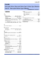
Function Specifications
General Specifications
Table A2.2 General Specifications
Item
Current consumption
External dimensions
Weight
Operating temperature range
Operating humidity range
Operating atmosphere
Storage temperature range
Storage humidity range
Specifications
220 mA (5 V DC)
28.9 (W) × 100 (H) × 83.2 (D) mm
0.1 kg
0 to 55C
10-90% RH (non-condensing)
Free of corrosive gases and heavy dust
-20 to 75C
10-90% RH (non-condensing)
The other specifications comply with the common specifications of the FA-M3.
Communications Specifications
Table A2.3 Communications Specifications
Item
Transmission speed
Transmission media
Transmission distance
Transmission channel
configuration
Maximum number of subunits
RAS features
A2.3
Specifications
10 Mbps
2-core fiber-optic cable
(hard plastic clad quartz fiber-optic H-PCF)
Maximum total distance: 200 m
Maximum distance between stations: 200 m
Star configuration only
7 (or 6 if F3SP20 or F3SP30 is used)
Shutdown I/O contact output on transmission channel error
Reporting of transmission channel error location (ERR LED lit)
Operating Environment
This module is compatible with all CPU modules. Logging of transmission channel error
location to an error log is available with F3SP21/F3SP25/F3SP35 (Rev. 8 or later),
F3SP05, F3SP08, F3SP28, F3SP38, F3SP53, F3SP58, F3SP59, F3SP66, F3SP67,
F3SP71 and F3SP76, as well as WideField3, WideField2, WideField, and Ladder
Diagram Support Program M3 (Rev. 1.08 or later).
\
IM 34M06H45-01E
5th Edition : Jan. 2012-00
A2-2
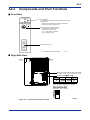
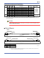
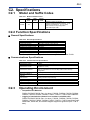
A2.4
Components and Their Functions
Front View
2 3
9 01
4 56
SUB UNIT
NO.
RDY indicators:
Green when the internal circuitry is functioning normally.
ERR indicators:
Red when the module fails to detect an input signal
from the fiber-optic connection port.
Unit Number Switch (Subunit number)
Specifies the unit number (0 to 7).
0: Unit number of main unit
1 to 7*: Unit number of subunits
8 to 9: Cannot be used
7 8
Optical connector port
*: 1 to 6 if F3SP20 or F3SP30 is used
FA0231.VSD
Right Side View
1 2 3 4 5 6 7 8
Figure A2.1 Components and Their Functions
\
IM 34M06H45-01E
5th Edition : Jan. 2012-00
A2-3
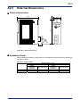
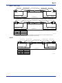
A2.5
External Dimensions
External Dimensions
83.2
2 3
SUB UNIT
NO.
7 8
100
4 56
9 01
2
28.9
r
a
Figure A2.2 External Dimensions
Installation Depth
When installing the module, always take into consideration space required for bending of
cords and cables.
Table A2.4 Bending Radius
Fiber-optic cord
Fiber-optic cable
Bending Radius, r (mm)
KF-07 (a = 18.3)
CF-2071, CF-2071H (a = 35.0)
During
During
installation
When Secured
installation
When Secured
(temporary)
(temporary)
15 or larger
50 or larger
15 or larger
50 or larger
50 or larger
100 or larger
\
IM 34M06H45-01E
5th Edition : Jan. 2012-00
Blank Page
A3-1
A3. System Configuration
A3.1
Fiber-optic FA-bus System Configuration
In a Fiber-optic FA-bus system configuration, FA-bus modules are installed in main unit
and subunits, and then connected using fiber-optic cables.
Main unit
Subunits
A3.1.1
:
:
Unit with CPU module installed
Units used for main unit system extension
(with no CPU module installed)
Restrictions on System Configuration
The following table lists some restrictions when configuring a Fiber-optic FA-bus system.
Table A3.1 Restrictions when Configuring a Fiber-optic FA-bus System
Item
Maximum total distance per system
Number of connectable subunits
Number of Fiber-optic FA-bus
modules installable in a main unit
Number of Fiber-optic FA-bus
modules installable in a subunit
Specifications
200 m
7 max.*
7 max.*
1 max
Modules installable in a subunit
All I/O modules and special modules except for
- Ethernet interface modules,
- NX Interface modules,
- FL-net Interface modules,
- FA Link modules,
- FA Link H modules,
- Fiber-optic FA Link H modules,
- Hard Disk modules,
- PC Card modules and
- YHLS master modules.
Unit number setting
(rotary switch located on the front of
the module)
Main unit: 0
Subunits: 1 to 7* (no duplicates allowed)
*: Up to 6 subunits are allowed if F3SP20 or F3SP30 module is used.
A3.1.2
Connection Topology
Fiber-optic FA-bus modules can only be connected using a star topology.
Star Configuration
Unit 0
Unit 1
Unit 2
Subunits (7 max.*)
Main unit
Unit 3
*: 6 max. when using F3SP20 or F3SP30
FA0311.VSD
Tips
IM 34M06H45-01E
5th Edition : Jan. 2012-00
A3-2
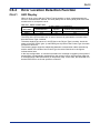
The following figures show example configurations when using both FA-M3 and FA500 modules.
Star Configuration
FA-M3
FA500
Main unit
FA-M3
FA-M3
Subunits (7* max.)
*: 6 max. when using F3SP20 or F3SP30)
FA0321.VSD
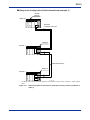
Daisy-Chain + Star Configuration
FA-M3
FA-M3
FA-M3
(L3LR01-0N)
FA500
(LR20-0N)
FA-M3
Main unit
FA500
Subunits (7* max.)
*: 6 max. when using
F3SP20 or F3SP30
FA-M3
FA500
FA0322.VSD
When using FA-M3 with FA500 modules, do not use a FA500 module as the main unit.
For the configuration examples shown above, the following modules cannot be installed in FA500
subunits:
- Expansion module (EU10-0N)
- SUMINET communications module (LS01-0N)
- Monitor module (LC01-N)
- Personal computer Link module (LC02-0N)
IM 34M06H45-01E
5th Edition : Jan. 2012-00
A4-1
A4. Pre-operation Setup and Cable
Connection
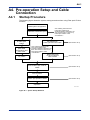
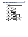
A4.1
Startup Procedure
The following figure shows the system startup procedure when using Fiber-optic FA-bus
modules.
Build system configuration
See "Cabling Instructions for
Fiber-optic Cables" from
Sumitomo Electric Industries, Ltd.
See “ Documents on How to Lay
Fiber-optic Cables” under
“ Introduction.”
Determine instrument layout
Determine routes
for Fiber-optic
cables
Set switches on
Fiber-optic FA-bus module
Determine fiberoptic cable
specifications and
place order
(See Section A4.2)
See "Cabling Instructions for
Fiber-optic Cables" from
Sumitomo Electric Industries, Ltd.
See “Documents on How to Lay
Fiber-optic Cables” under
“ Introduction.”
Mount Fiber-optic
FA-bus module on
base module
Lay cables
Connect fiber-optic cords or
cables
(See Section A4.3)
(See Section A4.4)
Turn on power
Perform pre-operation checks
(See Section A4.5)
Operation
FA0411.VSD
Figure A4.1 System Startup Workflow
IM 34M06H45-01E
5th Edition : Jan. 2012-00
A4-2
A4.2
Setting Switches
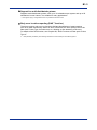
A4.2.1
Setting Unit Number Switch
SUB UNIT
23
456
9 01
For a Fiber-optic FA-bus module, set its unit number decimal rotary switch located on
the front face of the module to the number of the unit where it is installed.
NO.
7 8
FA0421.VSD
Figure A4.2 Unit Number Switch Located on Front Face of Module
The unit number ranges from 0 to 7*.
Do not duplicate unit numbers between Fiber-optic FA-bus modules.
For all modules installed in the main unit, set the unit number to 0.
Table A4.1 Unit Number Switch Settings
Switch Setting
0
1 to 7*
8 to 9
Description
For modules installed in the main unit
(Factory setting: 0)
For modules installed in subunits
Not used (cannot be used)
* 1 to 6 when F3SP20 or F3SP30 is used
CAUTION
-
-
The Fiber-optic FA-bus module will not operate normally if duplicate unit numbers
exist. Furthermore, if the module is accessed using the WideField3 software when
there are duplicate unit numbers, receiving will fail and the software will terminate.
If a F3LR01 is set as a subunit (1 to 7) and yet installed along with the sequence
CPU in the same base module, the sequence CPU may detect an error and clear its
memory.
IM 34M06H45-01E
5th Edition : Jan. 2012-00
A4-3
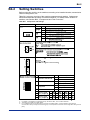
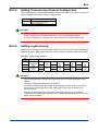
A4.2.2
Setting Condition Switches
Use the DIP switch (SW1 to SW4) located on the right side of the module to set up the
following functions.
Enabling/Disabling Shutdown Output on Transmission Channel Error
Function
Use SW1 for this setting.
This switch is valid only for subunits.
For the main unit, set the switch to OFF (factory setting is ON).
For details on the Shutdown Output function, see Section A7, “RAS Functions”
Table A4.2 Condition Switch Settings
Switch
Number
1
2 to 4
Function
Shutdown output on
transmission channel error
Not Used
ON
Shutdown
output
OFF
Factory
Setting
Hold output
ON
OFF
TIP
If the module has its Shutdown Output function (Condition Switch No. 1) set to ON, it treats a
transmission channel error due to, say, a broken fiber-optic cable or a powered-off substation in the
transmission channel as a major failure of the sequence CPU module. Thus, if a transmission channel
error occurs with Condition Switch No. 1 set to ON, the output is either shut down or held according to
the DIO Setup ("Reset" or "Hold") of the CPU configuration.
CAUTION
Always set switch numbers 2, 3 and 4 to OFF.
Turning on these switches may affect normal module operation.
IM 34M06H45-01E
5th Edition : Jan. 2012-00
A4-4
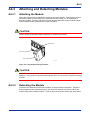
A4.3
Attaching and Detaching Modules
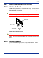
A4.3.1
Attaching the Module
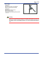
Figure A4.3 shows how to attach this module to the base module. First hook the anchor
slot at the bottom of the module to be attached onto the anchor pin on the bottom of
the base module. Push the top of this module towards the base module until the yellow
anchor/release button (yellow button) clicks into place.
CAUTION
Always switch off the power before attaching or detaching a module.
Base module
Anchor pin
This module
F01.VSD
Figure A4.3 Attaching/Detaching the Module
CAUTION
DO NOT bend the connector on the rear of the module by force during the above
operation. If the module is pushed with improper force, the connector may bend causing
an error.
A4.3.2
Detaching the Module
To remove this module from the base module, reverse the above operation. Press the
anchor/release button (yellow button) on the top of this module to unlock it and tilt the
module away from the base module. Then lift the module off the anchor pin at the base.
IM 34M06H45-01E
5th Edition : Jan. 2012-00
A4-5
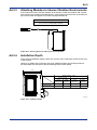
A4.3.3
Attaching Modules in Intense Vibration Environments
If the module is used in intense vibration environments, fasten the module with a screw.
Use screws of type listed in the table below. Insert these screws into the screw holes on
top of the module and tighten them with a Phillips screwdriver.
Screw Required
M4-size binder screw 12 to 15 mm long
(Or 14 to 15 mm if fitted with a washer)
FA0432.VSD
Figure A4.4 Securing Screws on Fiber-optic FA-bus Modules
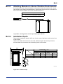
A4.3.4
Installation Depth
The module’s installation depth is 85.5 mm from the rear of the base module to the front
of this module.
However, if cables with connectors are used, additional space should be provided to
accommodate the connectors and the bending radius of the cables.
85.5
83.2
Bending Radius, r (mm)
KF-07 (a=18.3)
During
Installation
(temporary)
When
Secured
Fiber-optic cord
15 or larger
50 or larger
Fiber-optic cable
—
—
CF-2071, CF-2071H (a=35.0)
During
When
Installation
Secured
(temporary)
15 or larger
50 or larger
50 or larger
100 or larger
r
a
FA0433.VSD
Figure A4.5 Installation Depth
IM 34M06H45-01E
5th Edition : Jan. 2012-00
A4-6
A4.4
Connecting Fiber-optic Cables
A4.4.1
Cable Preparation
Use the following fiber-optic cables for connecting Fiber-optic FA-bus modules.
Specifications for Fiber-optic Cable
Table A4.3 Specifications for Fiber-optic Cable Cores
DK-HPF200/230
(for KM60)
SWCC Showa Cable Systems
Product name
Vendor
Core diameter
Clad diameter
HC-20/07
(for KM60, KM61, KM62, KM65)
Sumitomo Electric Industries
2005 m
230 010 m
7 dB/km max. ( =0.85 m, Ta=25C) *1
7 dB/km max. ( =0.81 m, Ta=25C)
Transmission loss
*1: The specifications of the fiber-optic cords and cables in the manual assume transmission loss of λ = 0.81 μm.
Table A4.4 Specifications for Fiber-optic Cable Connectors
Product name
Vendor
Specifications
KF-07
(for KM60)
SWCC Showa Cable
Systems
Bi-directional, lever lock,
bonding, polished
CF-2001H, CF-2071H
(for KM60, KM61, KM62)
CF-2011, CF-2071
(for KM65)
Sumitomo Electric Industries
Sumitomo Electric Industries
Bi-directional, lever lock,
bonding, polished
Bi-directional, lever lock,
crimping, cut
List of Fiber-optic Cables
Fiber-optic Cords for Connections inside Panel
(with bonding and polishing treatment on optical connector)
Model
KM60
Suffix
Code
-S06
-001
-003
Style
Code
-
-
-
Option
Code
-
-
-
Description
Cable length: 0.6 m
Cable length: 1.0 m
Cable length: 3.0 m
Max. Transmission
Loss (dB)
2.60
2.60
2.60
Applicable
Module
F3LR01, F3LR02,
F3LP12
Fiber-optic Cables for Indoor Use with Tension Members
(with bonding and polishing treatment on optical connector)
Model
KM61
Suffix
Code
-010
-100
-150
-200
Style
Code
-
-
-
-
Option
Code
-
-
-
-
Description
Cable length: 10 m
Cable length: 100 m, a pulling eye on one end
Cable length: 150 m, a pulling eye on one end
Cable length: 200 m, a pulling eye on one end
Max. Transmission
Loss (dB)
1.10
1.10
1.54
1.95
Applicable
Module
F3LR01, F3LR02,
F3LP12
Note: For information on pulling eyes, see the fiber-optic lead-in cable laying pulling-eye assembly diagram in this manual.
Note: The KM62 cable may be used in wet environments (but not in submerged environments).
Fiber-optic Cables for Indoor Use with Tension Members
(with crimping and cutting treatment on optical connector)
Model
KM65
Suffix
Code
-001
-002
-003
-004
-005
-007
-010
-012
-015
-020
-025
-030
Style
Code
-
-
-
-
-
-
-
-
-
-
-
-
Option
Code
-
-
-
-
-
-
-
-
-
-
-
-
Description
Cable length: 1 m
Cable length: 2 m
Cable length: 3 m
Cable length: 4 m
Cable length: 5 m
Cable length: 7 m
Cable length: 10 m
Cable length: 12 m
Cable length: 15 m
Cable length: 20 m
Cable length: 25 m
Cable length: 30 m
Max. Transmission
Loss (dB)
2.00
2.00
2.00
2.00
2.00
2.00
2.00
2.00
2.00
2.00
2.00
2.00
Applicable
Module
F3LR01
(Max. 200 m)
F3LR02
(Max. 200 m)
F3LP12
(Max. 1000m)
Note: The KM62 cable may be used in wet environments (but not submerged environments).
Note: KM65 cables are not supplied with pulling eyes. If pulling eye is required, use the KM61 or KM62 cables.
IM 34M06H45-01E
5th Edition : Jan. 2012-00
A4-7
Fiber-optic Cables for Outdoor Use with Tension Members
(with bonding and polishing treatment on optical connector)
Model
Suffix
Code
Style
Code
Option
Code
KM62
-100
-200
-300
-400
-500
-600
-700
-800
-900
-L01
-
-
-
-
-
-
-
-
-
-
-
-
-
-
-
-
-
-
-
-
Description
Cable length: 100 m, a pulling eye on one end
Cable length: 200 m, a pulling eye on one end
Cable length: 300 m, a pulling eye on one end
Cable length: 400 m, a pulling eye on one end
Cable length: 500 m, a pulling eye on one end
Cable length: 600 m, a pulling eye on one end
Cable length: 700 m, a pulling eye on one end
Cable length: 800 m, a pulling eye on one end
Cable length: 900 m, a pulling eye on one end
Cable length: 1000 m, a pulling eye on one end
Max.
Transmission
Loss (dB)
1.10
1.95
2.72
3.43
4.10
4.73
5.33
5.91
6.46
7.00
Applicable
Module
F3LR01
(Max. 200 m)
F3LR02
(Max. 200 m)
F3LP12
(Max. 1000m)
Note: For information on pulling eyes, see the fiber-optic lead-in cable laying pulling-eye assembly diagram in this manual.
CAUTION
KM6 cables cannot be used in submerged environments. Contact Yokogawa’s sales
office for alternative solutions.
External Diagram
KM60
Optical connector
Optical connector
Serial No.
Fiber-optic cord
+e
L + tolerance -0
Optical connector
Identification marking
Identification marking
Optical connector
Fiber-optic cord
+e
L + tolerance -0
Length L (m)
L
3
Tolerance + e (m)
0.20
FA0441.VSD
Note: Fiber-optic cord (KM60) is available in two types with optical connectors of different looks but customers cannot
specify the connector type when placing an order.
IM 34M06H45-01E
5th Edition : Jan. 2012-00
A4-8
KM61, KM62
Optical connector
Indentification marking
Protective tape winding
or protective coating
(End with sheath removed)
Identification marking
Optical connector
(End with sheath removed)
Fiber-optic cable
Tension member
Tension member
200±50mm
200±50mm
L + tolerance +e
-0
Indentification marking
Optical connector
Protective tape winding
or protective coating
(End with sheath removed)
Identification marking
Optical connector
(End with sheath removed)
Fiber-optic cable
Tension member
200±50mm
Length L (m)
5<L
KM65
200±50mm
Tolerance +e (m)
30
30<L
Tension member
L + tolerance +e
-0
0.50
L x 0.03 (3%)
FA0442.VSD
Note: Fiber-optic cable (KM61, KM62) is available in two types with optical connectors of different looks but customers
cannot specify the connector type when placing an order.
Optical connector
Indentification marking
Protective tape winding
or protective coating
Identification marking
Optical connector
(End with sheath removed)
(End with sheath removed)
Fiber-optic cable
200mm
+70mm
-50mm
Length L (m)
L
15
Tension member
Tension member
L + tolerance +e
-0
200mm
+70mm
-50mm
Tolerance +e (m)
0.20
5<L
15
0.30
15<L
30
0.50
FA0442B.VSD
IM 34M06H45-01E
5th Edition : Jan. 2012-00
A4-9
Cross-sectional view
KM60
Identification marking (HC-20/07)
Serial No. (DK-HPF200/230)
1
1
2
3
2.2 ±0.3mm
4
5
Core (quartz glass)
2
Clad (fluorinated acrylate resin)
3
Cover (fluorine-based resin)
4
Reinforcer (aromatic high tensile fiber)
5
Outer cover (heat-resistant PVC black)
FA0443.VSD
KM61, KM62, KM65
1
1
Fiber-optic single-core cord
2
2
Tension member (plastic-covered steel wire)
3
3
Lacing (plastic lacing)
4
4
Inclusion (plastic yarn or fiber)
5
5
Holding tape (plastic fiber)
6
6
Heat-resistant PVC sheath (KM61, 65), LAP sheath (KM62)
Model Manufacturer Item code
External Dimensions()
KM61
KM65
2-C-V
8.4mm ±1.0
KM62
2-C-LAP
10.0mm ±1.0
FA0444.VSD
Connector (Top View)
CF-2071H and CF-2071 (for cables KM60, KM61, KM62, and KM65)
17.0mm
8.0mm
23.0mm
18.0mm
FA0445.VSD
KF-07 (for cable KM60)
(8.2mm)
(21mm)
(18.3mm)
FB0245B.VSD
IM 34M06H45-01E
5th Edition : Jan. 2012-00
A4-10
Fiber-optic Lead-in Cable Laying Pulling-Eye Assembly Diagram
Unit: mm
6 2
1
3
2
4
5
30 * 5
Rigid section 70
6
7
Rigid section 50
8
Approx. 500
No.
When performing lead-in work, connect the pulling eye to the tow
line through a swivel which is attached to the head of the pulling
eye as shown in the figure below.
Tow line
Pulling eye
Fiber optic cable
Swivel
Components
Qty.
1
Pulling eye
1
2
Stopper screw (M6)
4
3
Flexible pipe
1
4
Terminal spacer
1
5
Vinyl tape
6
Tension member
7
Optical connector
8
Fiber-optic cable
FA0446.VSD
Fiber-optic Cables from Sumitomo Electric Industries
Table A4.5 Cords and Cables without Connectors from Sumitomo Electric
Fiber-optic cord
Fiber-optic cable
Type
H-PCF2 core cord
2-C-V (for indoor use)
2-C-LAP (for outdoor use)
Specifications
DCV-HC-20/07
2×CCV-HC-20/07
2×CCV-HC-20/07
Compatible Modules
F3LR01, F3LR02, F3LP12*1
F3LR01, F3LR02, F3LP12*1
F3LR01, F3LR02, F3LP12*1
Table A4.6 Cords and Cables with Connectors on Both Ends from Sumitomo Electric
Type
Fiber-optic cord
2-C-V
(cable for indoor
use)
2-C-LAP
(cable for outdoor
use)
Model
2001H-MM-L
2071H-MM-L
Specifications
P:
DCV-HC-20/07
L=length
Up to 5m
Shape
φ2.2mm×2
core cord
Compatible Modules
F3LR01, F3LR02, F3LP12
2001H-MM-0.2/L
2×CCV-HC-20/07
2071H-MM-0.2/L
-P*2
*1
φ8.4mm cable
F3LR01, F3LR02, F3LP12
PVC sheath
2001H-MM-0.2/L
2×CCV-HC-20/07
2071H-MM-0.2/L
-P*2
*1
φ10mm cables
PE sheath with F3LR01, F3LR02, F3LP12
metal tape
*1: Module, distance
*2: Pulling eye
F3LR01, F3LR02
0 to 200 m
F3LP12
0 to 1000 m
Recommended for cables longer than 50m
CAUTION
For product enquiries or order placement, contact an authorized sales agent of
Sumitomo Electric Industries, quoting the manufacturer (Sumitomo Electric Industries),
type, model and specifications information.
CAUTION
Do not use products other than those specified above. Doing so may result in hardware
failure, incorrect operation or inability to achieve designed performance.
IM 34M06H45-01E
5th Edition : Jan. 2012-00
A4-11
Products to be Used When Laying Cables
When laying fiber-optic cables, use the following products from Sumitomo Electric
Industries.
Table A4.7 Products to be Used When Laying Cables
Optical connector
Name
Contact/polishing type
Solderless/cut type
Optical connector
Solderless/cut type
connection tool
Optical power tester (for testing work on optical connector)
CF-2001H
CF-2011
Model
CF-2071H
CF-2071
CAK-1020
CAK-0057
CAT-2700
CAT-2001H
Master fiber set (for testing work on optical connector)
CAT-2001H (HG)
Cabling Instructions for Fiber-optic Cords/Fiber-optic
Technical Materials No.
Cables
1769B
Manuals for
Fiber-optic
Connector
Assembling
Tool
CAK-1020
(for
CF-2011)
(Fiber-optic Technical
Sumi-Link DF
Materials No. 1100)
series
Fiber-optic Connector Assembling Tool CAK-0052 (for CF-2071H) (Fiber-optic
Technical Materials No. 1083)
CAUTION
Do not use products other than those specified above. Doing so may result in hardware
failure, incorrect operation or inability to achieve designed performance.
IM 34M06H45-01E
5th Edition : Jan. 2012-00
A4-12
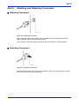
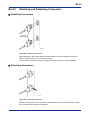
A4.4.2
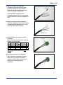
Attaching and Detaching Connectors
Attaching Connectors
FA0447.VSD
Figure A4.6 Attaching Connectors
When attaching a fiber-optic cable connector, always hold the connector (never the
cable), and then insert it until it clicks into place.
Then, hold the connector and pull it lightly to make sure that it is correctly seated.
Detaching Connectors
FA0448.VSD
Figure A4.7 Detaching Connectors
Hold the center portion of the connector (indicated by the arrow in the figure) to unlock
the connector, and then pull it toward you.
IM 34M06H45-01E
5th Edition : Jan. 2012-00
A4-13
A4.4.3
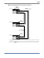
Precautions When Connecting Fiber-optic Cables
Handle fiber-optic cables with care.
Before laying fiber-optic cables, read manuals available from Sumitomo Electric
Industries. Engage a professional contractor specializing in laying fiber-optic cables.
Read “Documents on How to Lay Fiber-optic Cables” under “Introduction” of this manual
and the “Fiber-optic Cable Laying Instructions” (IM34M06C92-01E).
WARNING
-
Always connect and disconnect fiber-optic cables when the system is offline.
Connecting or disconnecting fiber-optic cables when the system is online may affect
normal system operation.
CAUTION
Observe the following precautions when connecting fiber-optic cables.
- Never touch the core of optical connectors with your bare hands and protect them
from dirt and dust.
Dust, dirt and oil from hands may result in degraded transmission performance or
even communications error.
Attach the cover during storage.
- When laying fiber-optic cords or fiber-optic cables, keep the elongation within 0.7%
of permissible elongation percentage. When the cable is secured, the elongation
should be within 0.2% of permissible elongation percentage.
Beyond these elongation limits, fiber-optic cables may break.
For this purpose, refer to Table 4.8 and take care not to subject fiber-optic cables to
excessive tensile impact, bending or twisting. Always pull an fiber-optic cable by its
tension member.
Table A4.8 General Mechanical Characteristics for Fiber-optic Cords and Cables
Tensile Strength (N)
Bending Radius (mm)
Lateral
Pressure
Twisting
Fiber-optic Cord
During laying < 98
When secured = 0
During laying = 15 min.
When secured = 50 min.
< 180°/2 m
Fiber-optic Cable
During laying < 735
When secured = 0
During laying = 50 min.
When secured = 100 min.
980 N/50 mm
(Should be
temporary)
< 90°/2 m
You should strictly observe the restrictions on permissible tensile load specified in the
catalog or technical specification of fiber-optic cables when laying cables.
When securing cables, do not subject connectors and cables to tensile force.
For on-site treatment, we recommend using crimp-on cutting type connectors.
IM 34M06H45-01E
5th Edition : Jan. 2012-00
A4-14
A4.5
Pre-operation Checks
A4.5.1
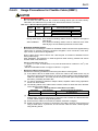
Checking Transmission Loss
Measure the transmission loss of fiber-optic cables after laying. Exercise care during
laying as excessive tension, bending and pressure during cable laying may cause
cables to break or crack. The following table shows the transmission loss of fiber-optic
cables and permissible transmission loss for the Fiber-optic FA-bus module.
Table A4.9 Transmission Loss Table for Fiber-optic Cables (up to 200 m)
Length of
Fiber-optic Cable
(HC-20/07)
10
20
30
40
50
60
70
80
90
100
110
120
130
140
150
160
170
180
190
200
Maximum Transmission Loss (dB)
(with bonding and
(with crimping and cutting
polishing treatment on
treatment on optical
optical connector)
connector)
1.10
2.60
1.10
2.60
1.10
2.60
1.10
2.60
1.10
2.60
1.10
2.60
1.10
2.60
1.10
2.60
1.10
2.60
1.10
2.60
1.19
2.69
1.28
2.78
1.37
2.87
1.45
2.95
1.54
3.04
1.62
3.12
1.71
3.21
1.79
3.29
1.87
3.37
1.95
3.45
Table A4.10 Allowable Transmission Loss for Fiber-optic FA-bus Modules
Cable Length (m)
Allowable Transmission Loss (dB)
0.6 to 200
4.0
CAUTION
-
-
Engage a professional contractor to lay fiber-optic cables.
Measure the transmission loss of fiber-optic cables after laying. Check that the
measured value for the actual cable length is better than the transmission loss for
the fiber-optic cable before laying.
If the transmission loss exceeds the permissible transmission loss for the Fiber-optic
FA-bus, normal communications will be affected. Replace the fiber-optic cable.
Measure the transmission loss of fiber-optic cables regularly.
WARNING
Using a cable with transmission loss exceeding permissible transmission loss for a
Fiber-optic FA-bus module may affect normal system operation.
IM 34M06H45-01E
5th Edition : Jan. 2012-00
A4-15
A4.5.2
LED Checks
After installing modules and connecting fiber-optic cables, check that the modules are
properly connected for communications. There should be no cable discontinuity or
improper connection.
Apply power to the units and perform the following checks.
The RDY (green) LED indicator must be lit
If this indicator is not lit, it may be because the Fiber-optic FA-bus module is not properly
mounted to the base module. Turn off the power and attach the module to the base
module correctly.
The ERR LED indicator must be off
When this LED indicator is on, communications is not allowed.
If the power of the destination unit is off, turn on its power and check whether the ERR
indicator turns off. If the ERR indicator is still on, it may be due to a transmission
channel error, such as cable discontinuity.
For troubleshooting information, see Section A8.3, “Troubleshooting when the ERR LED
is Lit.”
IM 34M06H45-01E
5th Edition : Jan. 2012-00
A4-16
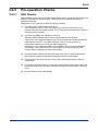
A4.6
Precautions When Applying Power
When turning on the power supply to the main unit and subunits, follow the sequence
below.
First confirm that the main unit and all subunits are turned off. Then turn on the power
supply to the main unit and the subunits simultaneously*, or turn on all subunits before
turning on the main unit.
A program starts execution when the main unit is turned on, regardless of whether
subunits are switched on. In situations where the powering sequence described above is
not adhered to, you should write your application so that it checks the status of subunits
using the special registers as listed on the next page. In this case, do not switch off and
switch on the main unit, or restart the CPU module, while a subunit is switched on.
*: By “simultaneously”, we mean, for instance, a system whereby a single switch turns on the power to the entire system.
CAUTION
If you have switched off the main unit, ensure that all subunits are switched off before
switching on the main unit. If you switch off and on the main unit while a subunit is
switched on, some modules in the subunit may not be recognized correctly by the CPU
module in the main unit.
IM 34M06H45-01E
5th Edition : Jan. 2012-00
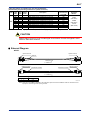
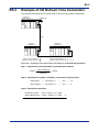
A4-17
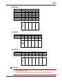
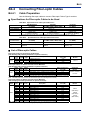
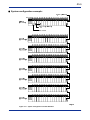
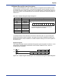
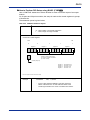
Module Recognition special registers
When a module installed in a main unit or subunit is recognized as accessible, the bit
corresponding to its slot position in the Module Recognition special registers is set to 1.
If a module cannot be read or written due to I/O module failure, subunit power failure or
some other reason, its corresponding bit in the Module Recognition special registers is
cleared to 0.
Table A4.11 Module Recognition Special Registers
Cateogry
Number
Module Recognition Special Registers
Name
Z41
Main unit
Z42
Subunit 1
Z43
Subunit 2
Z44
Subunit 3
Z45
Subunit 4
Z46
Subunit 5
Z47
Subunit 6
Z48
Subunit 7
Description
Slot
number 16
...
0
...
9
1
8
7
6
5
4
3
2
1
0
1
1
0
1
1
1
1
0: No module is mounted
or mounted module does not allow read and write.
1: Module is recognized as accessible.
FB0462.VSD
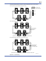
In situations where some subunits are turned on after the main unit, by checking the
Module Recognition special registers, a program can perform initialization setup of an
advanced function module installed in a subunit without waiting for the entire system to
be powered up.
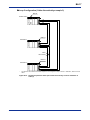
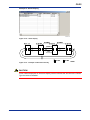
Sample Program:
This sample program copies the Module Recognition special register for subunit 1 to an
internal relay, and performs initialization of the module installed in slot 1 after it is
recognized as accessible.
0001
0002
M00033
I00001
MOV
Z00042
I00001
101
501
1
WRITE
$C000
FB0463.VSD
Figure A4.8 Sample Program Illustrating the Use of the Module Recognition Special Registers
IM 34M06H45-01E
5th Edition : Jan. 2012-00
Blank Page
A5-1
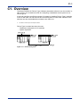
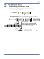
A5. Accessing Modules in a Subunit
A5.1
Slot Number in FA-M3
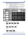
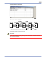
In FA-M3, slot numbers are used for accessing various modules.
A slot number indicates the position of the slot where a module is mounted and is a
3-digit integer with the following structure.
Slot number*1 within a unit
: 01 to 16
*1: Slot number runs sequentially from 01 to 16,
starting from the slot on the right of the power supply module.
Unit number
Main unit
Subunit
:0
: 1 to 7*2
*2: 1 to 6 if F3SP20 or F3SP30 is used.
FA0511.VSD
A module installed in a subunit can be accessed using ladder or BASIC, in the same
way as accessing a module mounted in the main unit.
IM 34M06H45-01E
5th Edition : Jan. 2012-00
A5-2
Fiber-optic FA-bus module
Slot number 001 002 003 004 005 006 007 008 009 010 011 012 013 014 015 016
Main unit
Power
supply
module
Add-on sequence CPU
(up to 3 CPUs)
CPU module
101
Subunit 1
102 103 104 105 106 107 108 109 110 111 112
Power
supply
module
Up to 7 units can be connected
201 202 203 204 205 206 207 208 209 210 211 212
Subunit 2
113 114 115 116
213
214
215 216
713
714
715 716
Power
supply
module
701 702 703 704 705 706 707 708 709 710 711 712
Subunit 7*
Power
supply
module
FA0512.VSD
*: Up to 6 units if F3SP20 or F3SP30 is used.
Figure A5.1 System Configuration and Slot Numbers
IM 34M06H45-01E
5th Edition : Jan. 2012-00
A6-1
A6. I/O Refresh Time
A6.1
Estimating I/O Refresh Time
To estimate the I/O refresh time, calculate the I/O refresh time separately for each port
of the main unit.
For details, refer to the following example.
=
I/O refresh time
Sum of I/O refresh times
for each type of access
There are 2 types of access, namely, 'read input' and 'write output'.
Calculate the I/O refresh time for each access type using the following formula and sum the values.
I/O refresh time for =
each access type
Time dependant on
access type
+
Time dependant
on transmission
distance
x
Number of modules,
converted to 16-point
basis
Access type
Number of modules:
Number of modules corresponding to access type,
converted to 16-point module basis.
F3SP22/28/38/
F3SP05/08/21 F3SP25/35 53/58/59/66/67 F3SP71/76
5.5 μs
9 μs
Read input
11 μs
10 μs
Write output
27 μs
21 μs
15 μs
6.5 μs
Formula:
1.0 μs x
(m)
: Transmission distance
100 (m)
FA0611.VSD
IM 34M06H45-01E
5th Edition : Jan. 2012-00
A6-2
A6.2
An Example of I/O Refresh Time
Calculation
This example calculates the I/O refresh time of the following system configuration.
F3LR01-0N
Power
supply
module
150m
Sub unit
Input: 32-point module x 2
Output: 32-point module x 1
FA0621.VSD
Figure 6.1 An Example of I/O Refresh Time Calculation (F3SP22, 28, 38, 53, 58, 59, 66 or 67)
Step 1: Calculate the ‘time dependant on transmission distance’
- 1.0µs x
150 (m)
= 1.5µs
100 (m)
Step 2: Calculate the ‘number of modules, converted to 16-point basis’
- Read Input
- Write Output
=
=
32 points ×2
32 points ×1
→
→
2×2
2×1
=
=
4
2
Step 3: Calculate the total time
Read input access = (9µs + 1.5µs) x 4 = 42.0µs
Write output access = (15µs + 1.5µs) x 2 = 33.0µs
I/O Refresh Time
(+
= 75.0µs
IM 34M06H45-01E
5th Edition : Jan. 2012-00
A7-1
A7. RAS Functions
A7.1
Error Location Detection Function
A7.1.1
LED Display
When an error occurs in a Fiber-optic FA-bus module, or when a cable discontinuity
occurs in a transmission channel, the error (ERR) LED or alarm (ALM) LED of the CPU
module turns on to report the error.
The LED of the CPU module turns on even if an error is generated in a module other
than the Fiber-optic FA Bus module.
To decide whether the cause of a lit LED lies in a Fiber-optic FA-bus module, check the
status of the RDY and ERR LEDs of the Fiber-optic FA-bus modules mounted in each
unit.
The following figure shows the relationship between fiber-optic cable discontinuity and
the status of the LED of the Fiber-optic FA-bus module.
Cable discontinuity
example 1
CPU module
ERR lit
AlM lit
Cable
discontinuity
Fiber-optic FA-bus module
ERR lit
Main Unit
0
Cable discontinuity
example 2
Subunit
1
CPU module
ERR ON
AlM ON
Main unit
Fiber-optic FAbus module
ERR lit
0
Subunit
1
Cable
discontinuity
Cable discontinuity
example 3
CPU module
ERR lit
AlM lit
Cable
discontinuity
Fiber-optic FA-bus module
ERR lit
Main unit
Fiber-optic FAbus module
ERR lit
0
Subunit
1
Cable
discontinuity
FA0711.VSD
Figure A7.1 Relationship between Fiber-optic Cable Discontinuity and Status of LED in the
Module
IM 34M06H45-01E
5th Edition : Jan. 2012-00
A7-2
A7.2
Shutdown Output on Transmission
Channel Error Function
A7.2.1
Overview of Shutdown Output Function
The Fiber-optic FA-bus module is equipped with a function, which forcefully shuts down
the output of the I/O module when a communications error occurs.
This function prevents an error in a Fiber-optic FA-bus module from affecting the entire
system or resulting in hazardous or unstable operation of the system.
For instance, when a cable discontinuity occurs in a transmission channel, the module
detects a communications error and immediately turns ff the output signals of each I/O
module to minimize risk.
The output shutdown on communications error function is available only for
configurations with one main CPU (without add-on CPUs).
TIP
If the module has its Shutdown Output function (Condition Switch No. 1) set to ON, it treats a
transmission channel error due to, say, a broken fiber-optic cable or a powered-off substation in the
transmission channel as a major failure of the sequence CPU module. Thus, if a transmission channel
error occurs with Condition Switch No. 1 set to ON, the output is either shut down or held according to
the DIO Setup ("Reset" or "Hold") of the CPU configuration.
A7.2.2
Shutdown Output of Subunit
CAUTION
-
-
-
To configure the system to reset the output of output modules in the event of a
power interruption on the main unit or a transmission channel error, turn on the
Shutdown Output switch (SW1) of the F3LR01 and set the DIO Setup for the
terminal to [Reset] in the CPU configuration.
This setting can be used with F3YD64-1F, F3YD64-1P, F3WD64-3F and
F3WD64-4F, but not with F3YD64-1A.*
To configure the system to hold the output in the event of a power interruption on
the main unit or a transmission channel error, turn off the Shutdown Output switch
(SW1) of the F3LR01 and set the DIO Setup for the terminal to [Hold] in the CPU
configuration.
The Reset Output function cannot be used in a multi-CPU system (system with addon CPUs). Always set to “Hold” in a multi-CPU system.
*: For F3YD64-1F and F3YD64-1P, the setting is available only when the modules are used with the F3SP28, 53, 58,
59, 66, 67, 71, or 76 CPU module.
The following table describes the operation of the module for various settings for your
reference.
Shutdown
Output switch
(SW1) of F3LR01
module mounted
in subunit
ON
OFF
FAIL Signal Contact
Output Status
Configuration
Setting of
CPU module
FAIL1
FAIL2
Reset
Hold
Reset
Hold
Shorted
Shorted
Open
Open
Open
Open
Shorted
Shorted
Operation of Output Module
Modules with
32 or less
output points,
F3YD64-1F, -1P,
F3WD64-3F, -4F
Reset
Hold
Hold
Hold
IM 34M06H45-01E
Modules with
64 output
points
(including
F3YD64-1A)
Hold
Hold
Hold
Hold
5th Edition : Jan. 2012-00
A7-3
A7.2.3
Procedure for Setting I/O Conditions
This section describes the procedure for using the Shutdown Output on Transmission
Channel Error function.
A7.2.3.1
Setting Condition Switches
Setting the condition switch on the right side of the module
1 2 3 4 5 6 7 8
O
F
F
Condition switch:
To enable the Shutdown Output function, you need to
set the condition switch located on the right side of the
Fiber-optic FA-bus module installed in the subunit.
Set DIP switch 1 according to the table in Section A2.4,
"Components and Their Functions".
Some modules may use the following DIP switch instead.
1
2
3
4
O
F
F
5
6
7
8
O
F
F
FA0721.VSD
Figure A7.2 Condition Switches on Right Side of the Module
IM 34M06H45-01E
5th Edition : Jan. 2012-00
A7-4
A7.2.3.2
DIO Setup in CPU Configuration
How to Perform DIO Setup using WideField3
To perform DIO Setup using WideField3, use the following procedure.
1. Select [Project]–[Project Settings] from the WideField3 menu bar.
2. Select [Input/Output Setup] from the Configuration pane of the displayed Project
Settings/Configuration window.
3. Click the cell for the slot installed with the module to be configured. Select the
Output Setup tab under Detailed Information. Set the [Output when Stopped] field
corresponding to the terminal number to [Reset (OFF)] or [Hold].
Figure A7.3 Setting I/O Conditions using WideField3
For details on WideField3 and its operation, see “FA-M3 Programming Tool WideField3
(Offline) User’s Manual” (IM34M06Q16-02E).
IM 34M06H45-01E
5th Edition : Jan. 2012-00
A7-5
How to Perform DIO Setup using BASIC (F3BP)
Use a CONTROL statement to select whether to reset or hold the output of output
modules.
On 16-point and 32-point modules, the setup is made to the control registers in groups
of 8 terminals.
The statement syntax is given below.
Syntax
CONTROL
m, 1 ; I
m : Slot number or numerical expression
I : Data, integer or integer variable
Content of Control Register
MSB
LSB
15
12
8
Register 4
Register 3
4
0
Register 2
Register 1
Resets or holds status in the
event of a master CPU failure
(0: Hold; 1: Reset)
Unused (always 0)
Register 4
Register 3
Register 2
Register 1
:
:
:
:
terminals 25 to 32
terminals 17 to 24
terminals 9 to 16
terminals 1 to 8
- The control register is reset to all zeroes at startup .
Example
CONTROL
:
206, 1 ; $ 0010
for the output module installed in slot 206, resets
terminals 9 to 16 and holds the remaining terminals in
the event of a master CPU failure.
FA0723.VSD
IM 34M06H45-01E
5th Edition : Jan. 2012-00
A7-6
A7.2.3.3
Operation Control in CPU Configuration
How to set up Operation Control using WideField3
To set up Operation Control using WideField3, use the following procedure.
1. Select [Project]–[Project Settings] from the WideField3 menu bar.
2. Select [Error Handling Setup] from the Configuration pane of the displayed Project
Settings/Configuration window.
3. Select [Continue to run] or [Stop] for [I/O module Error] and [Subunit Communication
Error] under Error-Time Action Setup.
Figure A7.4 Setting Operation Control using WideField3
How to set up Operation Control using BASIC (F3BP)
An I/O module error or subunit communications error generates an error in BASIC.
Design your application program to handle such errors.
IM 34M06H45-01E
5th Edition : Jan. 2012-00
A8-1
A8. Errors and Troubleshooting
A8.1
Troubleshooting Flowcharts
This section shows flowcharts that can be used for troubleshooting problems that may
occur with the Fiber-optic FA-bus module during operation.
ALM LED of
CPU Module is lit
Error in Fiber-optic
FA-bus module?
NO
Check the cause for the lit
ALM LED for the error module
and troubleshoot accordingly.
YES
RDY LED of
Fiber-optic FA-bus
module lit?
NO
See Section A8.2,
"When RDY LED is not Lit'.
YES
ERR LED of
Fiber-optic FA-bus
module lit?
YES
Locate the fault by
referring to Section A7.1,
"Error Location Detection
Function".
NO
See Section A8.3,
"When ERR LED is lit".
Is unit number
set correctly?
NO
YES
Are switches
inside the side cover
correctly set?
YES
Replace Fiber-optic FAbus module
Set the unit number correctly.
NO
Set the switches inside the
side cover correctly.
(Set SW2 to SW4 to off.)
End
FB0811.VSD
IM 34M06H45-01E
5th Edition : Jan. 2012-00
A8-2
A8.2
When RDY LED is Not Lit
RDY LED is not lit
Is correct voltage
supplied to the power
supply module?
NO
Apply proper voltage
YES
Is RDY LED lit on
other modules?
NO
Replace the power
supply module or the
base module
YES
Is module mounted
properly in its slot?
NO
Push the module inwards
until it clicks into place
(see Section A4.3).
YES
Is RDY LED
off even when module
is installed in another
slot?
YES
NO
NO
Is RDY LED lit?
Replace the
base module
YES
Replace Fiber-optic FAbus module
End
FB0821.VSD
IM 34M06H45-01E
5th Edition : Jan. 2012-00
A8-3
A8.3
When ERR LED is Lit
ERR LED is lit
Is fiber-optic cable
connected?
NO
Connect
fiber-optic cable
YES
Are all units
switched on?
NO
Turn on power to
all other units
YES
Is there a cable
discontinuity?
YES
Replace
fiber-optic cable
NO
Are the side
switches set
correctly?
NO
Set switches inside the
side cover correctly
(Set SW2 to SW4 to off)
YES
Replace fiber-optic FAbus module
YES
Is ERR LED lit?
NO
End
FB0831.VSD
IM 34M06H45-01E
5th Edition : Jan. 2012-00
Blank Page
Index A-1
FA-M3
Fiber-optic FA-bus, Fiber-optic FA-bus Type 2, FA-bus Type 2 Modules
Part A: Fiber-optic FA-bus Module
IM 34M06H45-01E 5th Edition
INDEX
C
cable
bending radius .....................................A2-3, A4-5
cable discontinuity ................. A4-14, A4-15, A7-1
cable list.............................................A4-6, A4-10
installation depth..................................A2-3, A4-5
precautions when connecting cables ......... A4-13
products to be used when laying cables .... A4-11
specifications for
fiber-optic cable connectors ............... A4-6
specifications for fiber-optic cable cores ...... A4-6
L
LED indicators
ERR (red)................................. A2-2, A4-14, A7-1
RDY (green)............................. A2-2, A4-14, A7-1
M
main unit ...................................................A3-1, A4-2
module recognition special registers ............... A4-17
P
precautions when applying power ................... A4-16
pulling eye...............................................A4-6, A4-10
S
shutdown output .......................................A4-3, A7-2
startup procedure............................................... A4-1
subunit ......................................................A3-1, A4-2
switches
Condition switch (DIP switch) .............A2-2, A4-3
Unit Number switch (SUB UNIT No.)...A2-2, A4-2
T
transmission loss ....................................A4-6, A4-14
troubleshooting ................................................. A8-1
IM 34M06H45-01E
5th Edition : Jan. 2012-00
Blank Page
TOC B-1
FA-M3
Fiber-optic FA-bus, Fiber-optic FA-bus Type 2, FA-bus Type 2 Modules
Part B: Fiber-optic FA-bus Type 2 Module
IM 34M06H45-01E
5th Edition
Part B of the manual describes the Fiber-optic FA-bus Type 2 Module
(F3LR02-0N).
IM 34M06H45-01E
5th Edition : Jan. 2012-00
Blank Page
B1-1
B1. Overview
The Model F3LR02-0N Fiber-optic FA-bus Type 2 Module (hereinafter referred to as ‘the
module’ or ‘this module’) is an interface module for configuring a distributed control
system on a fiber-optic FA-bus type 2.
A user can configure an efficient remote I/O system by installing Fiber-optic FA-bus Type
2 modules in the FA-M3 main unit and subunits and connecting them using fiber-optic
cables. Modules in the subunits can then be handled like modules in the main unit.
*1: I/O refers to contact input and output modules.
Fiber-optic FA-bus Type 2 module has two main uses:
-
Distributed configuration of I/O modules
System expansion
CPU module
Fiber-optic
FA-bus Type
2 module
Power
supply
module
Main unit
Fiber-optic
FA-bus Type
2 module
Power
supply
module
Subunit
Fiber-optic FA-bus type 2
FB0101.VSD
Figure B1.1 Remote I/O System
IM 34M06H45-01E
5th Edition : Jan. 2012-00
B1-2
B1.1
Features
The Fiber-optic FA-bus Type 2 module has the following features.
High-speed communications
The Fiber-optic FA-bus Type 2 module features 10 Mbps high-speed communications.
Users no longer have to worry about I/O refresh time during ladder programming.
Extended distance between stations
A master station can control remote stations*1. The maximum distance between two
stations is 500 m*2 and the maximum total distance is 1.4 km*3.
Master station
Substation 1
Terminal station
max. 500m
max. 1.4km
FB0111.VSD
Flexible unit configuration
All I/O modules, with some exceptions*4, can be installed in a substation. Modules
installed in a substation can be accessed the same way as modules installed in the
master station.
Simple setup
No specific remote I/O configuration (environment setup) is required.
Optical transmission
The use of fiber-optic cables for transmission delivers high noise immunity.
Master station
Substation
Fiber-optic Cable
FB0112.VSD
*1:
*2:
*3:
*4:
Subunit installed with a Fiber-optic FA-bus Type 2 module
GI-type H-PCF cables must be used for distance beyond 200m.
3 substations for daisy-chain configuration.
Except for Ethernet Interface modules, NX Interface modules, FL-net Interface modules, FA Link modules, FA Link H
modules, Fiber-optic FA Link H modules, Hard Disk modules, PC Card modules and YHLS Master modules.
Flexible system configuration
2 communications ports are provided, thus allowing both daisy-chain configuration and
loop configuration. Furthermore, multiple Fiber-optic FA-bus Type 2 modules can be
installed in one master station to build a mixed configuration.
For details, see Section B3.5, “Connection Topology”.
IM 34M06H45-01E
5th Edition : Jan. 2012-00
B1-3
Support for multi-distributed systems
Supports multi-distributed systems, with up to 32 substations per system and up to 56
substations in total. Hence, it is suitable for many applications.
*: These figures apply in configurations where only F3BU04 modules are used.
Early error location reporting (RAS *1 function)
The alarm monitor and error log functions facilitate identification of error locations
such as a cable discontinuity. When an error is detected, the Error (ERR) LED on the
fiber-optic FA-bus Type 2 module turns on, allowing on-site detection of the error.
For details of the RAS function, see Chapter B6, “RAS Functions of Fiber-optic FA-bus
Type 2”.
*1: RAS (Reliability Availability Serviceability) indicates the overall usability of automated equipment.
IM 34M06H45-01E
5th Edition : Jan. 2012-00
Blank Page
B2-1
B2. Specifications
B2.1
Model and Suffix Codes
Table B2.1 Model and Suffix Codes
Model
Suffix
Code
Style
Code
Option
Code
F3LR02
-0N
Remarks
Maximum total distance: 1.4 km
Maximum distance between units: 500 m
B2.2 Function Specifications
General Specifications
Table B2.2 General Specifications
Item
Current consumption
External dimensions
Weight
Operating temperature range
Operating humidity range
Operating atmosphere
Storage temperature range
Storage humidity range
Specifications
460 mA (5V DC)
28.9 (W) × 100 (H) × 83.2 (D) mm
0.12 kg
0 to 55C
10 to 90% RH (non-condensing)
Free of corrosive gases and heavy dust
-20 to 75C
10 to 90% RH (non-condensing)
The other specifications comply with the common specifications of the FA-M3.
Communications Specifications
Table B2.3 Communications Specifications
Item
Transmission speed
Transmission media
Transmission distance
Transmission channel
configuration
Maximum number of
substations
RAS features
Signal encoding
Access method
Number of I/O ports
Specifications
10 Mbps
2-core fiber-optic cable (hard plastic clad quartz fiber-optic H-PCF)
Maximum total distance: 1.4 km*1
Maximum distance between units: 500 m
Star, daisy-chain or loop configuration
56 substations*2
Shutdown output on transmission channel error function, error reporting
function, loop switching
Manchester encoding
Direct I/O access
2 ports
*1: 3 substations in daisy-chain configuration. The maximum total distance decreases if more substations are used (see
Table B3.2).
*2: Up to 32 substations are allowed per system if F3BU04 modules are used for all subunits.
B2.3
Operating Environment
-
Compatible CPU Modules:
F3SP21/F3SP25/F3SP35 (Rev. 8 or later), F3SP05, F3SP08, F3SP28, F3SP38,
F3SP53, F3SP58, F3SP59, F3SP66, F3SP67, F3SP71, F3SP76 and F3BP
-
Base modules that support slot number setup: F3BU04, F3BU05 and F3BU06
*:
-
Some base modules having the older type of nameplate do not support slot number setup.
For details, see B3.8, “Precautions.”
Logging of transmission channel error location is available with:
F3SP21/F3SP25/F3SP35 (Rev. 8 or later), F3SP05, F3SP08, F3SP28, F3SP38,
F3SP53, F3SP58, F3SP59, F3SP66, F3SP67, F3SP71, F3SP76 and WideField3,
WideField2, WideField, and Ladder Diagram Support Program M3 (Rev. 1.08 or
later).
IM 34M06H45-01E
5th Edition : Jan. 2012-00
B2-2
B2.4
Components and Their Functions
For details, see Section B4.2, “Setting Switches”.
Front View
RDY
ERR1
ERR2
LR02-0N
2 3
4
REMOTE
SUB UNIT
NO.
7 8
Unit number switch (subunit number):
Specifies a unit number (0 to 7)
0
: unit number of the main unit
1 to 7 : unit number of a subunit
8 to 9 : cannot be used
(factory setting is 0)
LEFT SLOT
345
67
NO.
A
E
89
F0 1 2
: Lit (green) when the internal circuit is functioning normally.
: Lit (red) when the module fails to detect an input signal
in port 1 and port 2 respectively.
5 6
9 0 1
LED indicators
RDY
ERR1, ERR2
BCD
1
Slot number switch (left slot number):
Specifies the leftmost slot number of the base module where a
Fiber-optic FA-bus Type 2 module is installed. (factory setting is 1)
1,3,5,7,9,B,D,F : valid values when using F3BU04
1,9
: valid values when using F3BU05 or F3BU06
1
: only valid value for other base modules
(F3BU09, F3BU13, F3BU16,)
2
Optical connector port
FB0231.VSD
Right Side View
Condition Switches
SW
number
1*1
Rear
Front
2
3
This figure is drawn
with the panel cover
removed.
1
2
3
4
5
6
7
Factory
setting
ON
Shutdown output on
transmission channel
error
Hold*2
Shutdown
ON
Port used
Port 1
Both ports*3
OFF
Loop
OFF
Transmission channel Daisy-chain
or star
configuration
Reserved
OFF
*1: Valid only for output modules installed in a sub-unit.
*2: Continues operation if transmission channel has been
secured and system operation is continued.
*3: When using both port 1 and port 2.
Condition switches
O
F
F
SW
Description
number
5
Port 1 light
intensity
6
7
Some modules may use the
following DIP switch instead.
5
6
7
8
OFF
O
F
F
8
1
2
3
4
4
Description
8
Port 2 light
intensity
Distance Between Stations (Length of optical fiber) (m)
OFF
OFF
OFF
OFF
ON
0
to
200
OFF
0
to
200
OFF
ON
200
to
300
200
to
300
OFF
ON
OFF
ON
300
to
400
ON
300
to
400
ON
ON
ON
400
to
500
400
to
500
FB0232.VSD
O
F
F
O
F
F
Figure B2.1 Components and Their Functions (F3LR02-0N)
IM 34M06H45-01E
5th Edition : Jan. 2012-00
B2-3
B2.5
External Dimensions
External Dimensions
83.2
RDY
ERR1
ERR2
LR02-0N
REMOTE
SUB UNIT
2 3
5 6
9 0 1
4
NO.
7 8
67
NO.
A
E
89
F0 1 2
LEFT SLOT
345
BC D
1
2
r
a
FB0241.VSD
Figure B2.2 External Dimensions of F3LR02-0N
Installation Depth
When installing the module, always take into consideration space required for bending of
fiber-optic cords and cables.
Table B2.4 Bending Radius
Fiber-optic cord
Fiber-optic cable
Bending Radius, r (mm)
KF-07 (a=18.3)
CF-2071, CF-2071H (a=35.0)
During
During
installation
When secured
installation
When secured
(temporary)
(temporary)
15 or larger
50 or larger
15 or larger
50 or larger
50 or larger
100 or larger
IM 34M06H45-01E
5th Edition : Jan. 2012-00
Blank Page
B3-1
B3. Fiber-optic FA-bus Type 2 System
Configuration
B3.1
What Is a Substation?
A Fiber-optic FA-bus Type 2 system contains the following elements.
Element
Station
Main unit
(master station)
Subunit
Substation
Description
A unit installed with a Fiber-optic FA-bus Type 2 module.
A unit installed with a CPU module.
Slots without a CPU module installed and are connected
to a main unit via a Fiber-optic FA-bus Type 2 modules for
system expansion. In a split-unit configuration, one
subunit consists of multiple substations.
The smallest unit in a Fiber-optic FA-bus Type 2 system.
Whether it is equivalent to a subunit depends on whether
we have a split-unit configuration.
In a split-unit configuration, a substation is a division of a
subunit. Without splitting, a substation is equivalent to a
subunit.
The following table lists some terminologies on system configuration used in this
manual.
Terminology
Terminal station
Station address
Master station module
Substation module
Terminal station module
Meaning
Substation at the end of a daisy chain.
General reference to a unit number and slot number
assigned to a station
Fiber-optic FA-bus Type 2 module installed in a master
station
Fiber-optic FA-bus Type 2 module installed in a substation
Fiber-optic FA-bus Type 2 module installed in a terminal
station
IM 34M06H45-01E
5th Edition : Jan. 2012-00
B3-2
B3.2
Substation Configuration
In a Fiber-optic FA-bus Type 2 system, a user can split a subunit into multiple
substations, as shown in Figure B3.1, “Substation Configuration Example”. Logically, a
subunit consists of 16 slots. Up to 7 subunits are allowed in a system.
Main unit
Slot 1
16
Subunit 1
Substation
Substation
Substation
Substation
Subunit 2
Substation
Substation
Substation
Substation
Subunit 7
Substation
Substation
Substation
Substation
FB0321.VSD
Figure B3.1 Substation Configuration Example
There are 6 patterns available for splitting subunits. Select an appropriate pattern to suit
your application.
Splitting
Pattern
Slot No.
1
2
3 4 5
6
7
9 10 11 12 13 14 15 16
F3BU09
(1)
(2)
F3BU06
(3)
F3BU06
F3BU06
F3BU04
F3BU04
F3BU04
(5)
F3BU04
F3BU04
F3BU04
‹ó
Empty
F3BU04
‹ó
Empty
F3BU04
2
2
F3BU04
F3BU06
Empty
Empty
F3BU04
F3BU04 Empty F3BU04
F3BU04
Number of
substations
F3BU04
(4)
(6)
8
3
3
F3BU04
F3BU04
‹ó
Empty
Empty
4
8
F3BU04 Empty
FB0322.VSD
Figure B3.2 Patterns for Splitting Subunits
When pattern (3) is used, for example, up to 7 subunits can be connected, providing a
maximum of 21 stations.
A 32-station system (maximum configurable system) can be configured by combining 6
sets of pattern (5) and 1 set of pattern (6). In pattern (6), only one module can be
installed per substation.
IM 34M06H45-01E
5th Edition : Jan. 2012-00
B3-3
B3.3
System Configuration and Slot Numbers
In FA-M3, slot numbers are used for accessing various modules.
A slot number indicates the position of the slot where a module is mounted and is a
3-digit integer with the following structure.
Slot number* within a unit
: 01 to 16
* : Slot number runs sequentially from 01 to 16,
starting from the slot on the right of the power supply module.
Unit number
main unit
Subunit
:0
: 1 to 7
FB0331.VSD
A module installed in a subunit can be accessed using ladder or BASIC, in the same
way as accessing a module mounted in the main unit.
IM 34M06H45-01E
5th Edition : Jan. 2012-00
B3-4
The following figure shows a system configuration example without split subunits, that is,
one substation equates to one subunit.
Such a configuration can be used if the number of substations required in a system is no
more than 7.
Fiber-optic FA-bus Type 2 module
Slot number
Main unit
(master station)
001
002 003 004 005 006 007
008
009 010 011 012
013
014 015
016
113 114 115
116
211 212 213 214 215
216
Power
supply
module
Add-on CPU (up to 3 CPUs)
CPU module
101 102 103
Subunit 1
(substation 1)
Subunit 3
(substation 3)
Subunit 4
(substation 4)
Subunit 5
(substation 5)
Subunit 6
(substation 6)
Subunit 7
(substation 7)
107 108 109
110 111 112
Power
supply
module
201 202
Subunit 2
(substation 2)
104 105 106
203 204 205 206
207 208
209 210
Power
supply
module
301
302 303
304 305 306 307
308 309 310 311 312
313
314 315
316
401
402 403
404 405 406 407
408 409 410 411 412
413 414
415
416
501
502 503
504 505 506 507
508 509 510 511 512
513 514 515
516
601
602 603
604 605 606 607
608 609
613 614 615 616
701
702 703
704 705 706 707
708 709 710 711 712
Power
supply
module
Power
supply
module
Power
supply
module
610 611 612
Power
supply
module
713 714
715
716
Power
supply
module
Maximum fiber-optic cable length between units: 500m
Maximum total fiber-optic cable length: 1260 m (7 substations)
FB0332.VSD
Figure B3.3 (a) System Configuration and Slot Numbers
If the number of substations required is more than 7, build a split-subunit configuration.
IM 34M06H45-01E
5th Edition : Jan. 2012-00
B3-5
Slot number
001 002 003
004 005 006
007 008 009 010 011 012
013
014 015 016
CPU
Main unit
(substation 1)
101
102 103 104 (substation 2) 105
106 107 108 (substation 3) 109
110 111 112 (substation 4) 113
114 115 116
201
202 203 204
(substation 6) 205
206 207 208 (substation 7) 209
210 211 212 (substation 8) 213
214 215 216
301
302 303 304 (substation 10) 305
306 307 308 (substation 11)309
310 311 312 (substation 12) 313
314 315 316
401
402 403 404 (substation 14) 405
406 407 408 (substation 15)409
410 411 412 (substation 16) 413
414 415 416
501
502 503 504 (substation 18) 505
506 507 508 (substation 19)509
510 511 512 (substation 20) 513
514 515 516
601
602 603 604 (substation 22) 605
606
607 608 (substation 23) 609
610 611 612 (substation 24) 613
614 615 616
701
702 703 704 (substation 26)705
706 707 708 (substation 27) 709
710 711 712 (substation 28) 713
714 715 716
Subunit 1
(substation 5)
Subunit 2
(substation 9)
Subunit 3
(substation 13)
Subunit 4
(substation 17)
Subunit 5
(substation 21)
Subunit 6
(substation 25)
Subunit 7
FB033.VSD
Figure B3.3 (b) System Configuration and Slot Numbers in a split-Subunit Configuration
IM 34M06H45-01E
5th Edition : Jan. 2012-00
B3-6
B3.4
Restrictions on System Configuration
The following table lists some restrictions when configuring a Fiber-optic FA-bus Type 2
system.
Table B3.1 Restrictions when Configuring a Fiber-optic FA Bus System
Item
Number of Fiber-optic
FA-bus Type 2 modules
installable in a master
station
Number of Fiber-optic
FA-bus Type 2 modules
installable in a substation
Modules installable in a
substation
Specifications
No restriction*
1 max.
All I/O modules and special modules except for
- Ethernet Interface modules,
- NX Interface modules,
- FL-net Interface modules,
- FA Link modules,
- FA Link H modules,
- Fiber-optic FA Link H modules,
- Hard Disk modules,
- PC Card modules, and
- YHLS Master modules.
* Provided the current capacity of the power supply module is not exceeded.
B3.5
Connection Topology
Fiber-optic FA-bus Type 2 modules can be connected using a loop, daisy chain or star
configuration. The following pages show examples for each of the configurations. But
first of all, you should understand the concept of “unit representation” described below.
Unit Representation
This example shows the unit representation of a Fiber-optic FA-bus Type 2 module
installed in a F3BU04, with the unit number switch (u) set to 3 and the slot number
switch set to 5.
With this setup, the leftmost slot of the F3BU04 is changed to slot 5 and the location
where the Fiber-optic FA-bus Type 2 module is installed is slot (8).
Substation
Unit 3
Slots 5 to 8
Power
supply
module
u3-s5
(8)
Fiber-optic FA-bus
Type 2 module
FB035.VSD
IM 34M06H45-01E
5th Edition : Jan. 2012-00
B3-7
Loop Configuration
A loop configuration connects the empty port of a terminal station of a daisy chain to the
master station to form a loop. In a loop configuration, if a cable discontinuity, substation
failure or substation shutdown occurs, the built-in RAS function will operate to increase
system reliability. Always form a loop with only one master station module.
Master station
Unit 0
Slots 1 to 6
Fiber-optic FA-bus
Type 2 module
(F3LR02-0N)
u0-s1
(6)
Power
supply
module
Fiber-optic Cable
Fiber-optic Cable
Substation
Unit 1
Slots 1 to 4
Substation
Unit 1
Slots 1 to 6
u1-s1
(4)
u4-s1
(6)
Power
supply
module
Power
supply
module
Fiber-optic Cable
Fiber-optic Cable
Substation
Unit 1
Slots 9 to 12
u1-s9
(12)
Power
supply
module
Substation
Unit 2
Slots 1 to 9
u2-s1
(9)
Power
supply
module
Fiber-optic Cable
FB0352.VSD
Figure B3.4 Loop Configuration
CAUTION
-
Mixing Fiber-optic FA-bus modules (F3LR01-0N) with Fiber-optic FA-bus Type 2
modules (F3LR02-0N) in a loop configuration is not allowed.
In a loop connection, port 2 of a station must be connected to port 1 of the other
station. Otherwise, the system will not operate normally.
IM 34M06H45-01E
5th Edition : Jan. 2012-00
B3-8
Daisy chain Configuration
A daisy chain configuration connects the master station to a substation, the substation to
another substation and so on to access a remote substation.
Master station
Unit 0
Slots 1 to 6
u0-s1
(6)
Fiber-optic FA-bus
Type 2 module
(F3LR02-0N)
Power
supply
module
Substation
Unit 1
Slots 1 to 6
u1-s1
(6)
Fiber-optic Cable
Power
supply
module
Substation
Unit 1
Slots 9 to 12
u1-s9
(12)
Fiber-optic Cable
Power
supply
module
Fiber-optic Cable
Substation
(terminal station)
Unit 4
Slots 1 to 9
u4-s1
(9)
Unused port
Power
supply
module
FB0353.VSD
Figure B3.5 Daisy chain Configuration
CAUTION
-
Mixing Fiber-optic FA-bus modules (F3LR01-0N) with Fiber-optic FA-bus Type 2
modules (F3LR02-0N) in a daisy chain is not allowed.
In a daisy chain connection, port 1 or port 2 of the master station must be connected
to port 1 of the substation. Port 2 of a substation must be connected to port 1 of
another substation. Otherwise, the system will not operate normally.
IM 34M06H45-01E
5th Edition : Jan. 2012-00
B3-9
Star Configuration
A star configuration consists of one-to-one connections between the master station and
each substation. In this configuration, a cable discontinuity, substation failure or
substation shutdown will not affect communications with other substations.
Master station
Unit 0
Slots 1 to 6
u0-s1 u0-s1
(6)
(5)
Power
supply
module
F3LR02-0N
F3LR01-0N
Fiber-optic Cable
Fiber-optic Cable
Fiber-optic cable
Substation
Unit 1
Slots 1 to 6
Substation
Unit 3
Slots 1 to 6
u1-s1
(6)
Power
supply
module
Power
supply
module
Fiber-optic Cable
Unused port
Substation
Unit 2
Slots 1 to 6
u2-s1
(6)
Substation
Unit 4
Slots 1 to 6
Power
supply
module
Power
supply
module
Unused port
FB0354.VSD
Figure B3.6 Star Configuration
CAUTION
-
Using Fiber-optic FA-bus modules (F3LR01-0N) together with Fiber-optic FA-bus
Type 2 modules (F3LR02-0N) is allowed in a star configuration.
In a star connection, port 1 or port 2 of the master station must be connected to port
1 of the each substation. Otherwise, the system will not operate normally.
IM 34M06H45-01E
5th Edition : Jan. 2012-00
B3-10
B3.6
System Configuration Design
Prerequisites
Before designing a system configuration, you must first confirm the following
information.
- the number of substations (the number of distributed substations)
-
the location of the substations
Design Flow
System
configuration
Number of substations (x)
required
x>7
YES*1
NO*2
Whether to split subunits depends on whether the
number of substations required in a system
exceeds 7. This significantly changes the system
configuration.
*1: See Figure 3.3 (b)
*2: See Figure 3.3 (a)
Select split pattern
and unit numbers
NO
Selectable?
YES
Check total distance
NO
Is total
within range?
YES
End
FB0361.VSD
Figure B3.7 Workflow for System Configuration Design
IM 34M06H45-01E
5th Edition : Jan. 2012-00
B3-11
B3.7
Total Distance
The maximum total distance for a fiber-optic cable is determined by the number of
substations. Table B3.2 shows the mapping between the number of substations and the
maximum total distance.
Do not lay cables such that the actual fiber-optic cable length exceeds the maximum
total distance, or the distance between two stations exceeds the maximum distance
allowed between stations (500 m).
Table B3.2 Mapping Between Number of Substations and Maximum Total Fiber-optic Cable
Extension
Number of
Substations
1
2
3
4
5
6
7
8
9
10
11
12
13
14
15
16
Maximum Total Distance (m)
Daisy Chain
500
1000
Number of
Substations
Loop
1000
1500
1420
1380
1340
1300
1260
1230
1190
1150
1110
1070
1030
1000
960
920
17
18
19
20
21
22
23
24
25
26
27
28
29
30
31
32
Maximum Total Distance (m)
Daisy Chain or Loop
880
840
800
760
730
690
650
610
570
530
500
460
420
380
340
300
The maximum total distance refers to the length of fiber-optic cable from the master
station to the terminal station in a daisy chain configuration, or the length of fiber-optic
cable in a complete loop of a loop configuration (see figure below). The maximum
allowable distance between two stations is 500 m.
Daisy chain Configuration
Master station
Substation 1
Terminal station
max 500m
Maximum total distance
FB0371.VSD
Loop Configuration
Master station
Substation 1
Substation n-1
Substation n
Maximum total distance
FB0372.VSD
IM 34M06H45-01E
5th Edition : Jan. 2012-00
B3-12
B3.8
Precautions When Changing Slot Number
-
Only the F3BU04, F3BU05 and F3BU06 base modules allow change of slot
numbers*1. For other base modules, the slot number always start from 1.
-
When setting addresses, do not duplicate unit/slot addresses within a system.
Splitting of the unit is not allowed for the master station (unit number = 0). The slot
number of the master station must be set to 1.
F3LR01 modules may be used together with F3LR02 modules in a star
configuration, but not in loop or daisy chain configurations.
-
*1:
Older versions of the F3BU04 or F3BU06 base module do not allow slot number change. Check the nameplate of the
base module for its version.
There are two types of nameplate: new and old. Base modules having the new type of nameplate always allow slot
number change. A base modules having an old type of nameplate allows slot number change only if its nameplate is
marked with "R01" but not otherwise.
- Slot number change allowed
[New nameplate type]
- Slot number change
not allowed
[Old nameplate type]
BASE
[Old nameplate type]
BASE
MODEL
:F3BU06
MODEL
SUFFIX
STYLE
:-0N
:S1
SUFFIX
STYLE
REV
SUPPLY
:00:
:-
SUPPLY
INPUT
INPUT
:-
OUTPUT
:-
DATE
:
NO.
:
BASE
MODEL
S1 ROM REV
-
SUFFIX
STYLE
F3BU06
S1 ROM REV
-
SUPPLY
INPUT
OUTPUT
OUTPUT
R01
NO.
NO.
IM 34M06H45-01E
5th Edition : Jan. 2012-00
B4-1
B4. Pre-operation Setup and Cable
Connection
B4.1
Startup Procedure
The following figure shows the system startup procedure when using Fiber-optic FA-bus
Type 2 modules.
Build system configuration
Determine instrument layout
Set switches of
Fiber-optic FA-bus Type 2
module
Determine routes
for fiber-optic cable
Determine fiberoptic cable
specifications and
place order
See "Cabling Instructions for
Fiber-optic Cables" from
Sumitomo Electric Industries, Ltd.
See “ Documents on How to Lay
Fiber-optic Cables” under
“ Introduction.”
(See Section B4.2)
See "Cabling Instructions for
Fiber-optic Cables" from
Sumitomo Electric Industries, Ltd.
See “ Documents on How to Lay
Fiber-optic Cables” under
“Introduction.”
Mount Fiber-optic
FA-bus Type 2 module on
base module
Lay cables
Connect fiber-optic
cords or cables
(See Section B4.3)
(See Section B4.4)
Turn on power
Pre-operation checks
(See Section B4.5)
Operation
FB0411.VSD
Figure B4.1 Startup Workflow
IM 34M06H45-01E
5th Edition : Jan. 2012-00
B4-2
B4.2
Setting Switches
Before using this module, set its switches according to its installed location, transmission
channel configuration, etc.
Table B4.1 gives an overview of the module components and settings. Subsequent
subsections describe the setup of individual switches. For details on the location of
switches, see Section B2.4, “Components and Their Functions.”
Table B4.1 Components and Settings
*1:
*2:
*3:
For details on investigation of cable discontinuity, see Section B6.1, “Error Location Detection.”
This setting is not valid for a master station.
For a substation with secured transmission channel to the master station, continues operation if the [Subunit
Communication Error] in the [Error-time Action] group on the Operation Control tab of the Configuration dialog is set to
[Run].
IM 34M06H45-01E
5th Edition : Jan. 2012-00
B4-3
B4.2.1
Setting Unit Number
Set the unit number using the unit number switch. This unit number will be used as an
address in programs. The following table lists the valid preset values.
Table B4.2 Unit Number Switch Settings
Switch Setting
0
1 to 7
8 to 9
Description
For modules installed in the main unit
(Factory setting: 0)
For modules installed in subunits
Not used (cannot be used)
CAUTION
-
-
B4.2.2
Always set the unit number of the Fiber-optic FA-bus Type 2 module installed in the
main unit to 0. With any other value, the memory of the CPU module may be
cleared.
The unit number for a substation can be set to any integer from 1 to 7 (inclusive).
Modules within the same system should not be given the same station address.
Setting Slot Number
This switch setting changes the slot number of the base module. Changing the starting
slot number of a base module allows multiple stations to share the same unit number.
Always set the slot number of the master station to 1.
IM 34M06H45-01E
5th Edition : Jan. 2012-00
B4-4
F3BU04
Left Slot Number
1
3
5
7
9
B (11)
D (13)
F (15)
Slot Number
—
—
—
—
—
—
—
—
1
2
3
4
3
4
—
—
5
6
7
8
7
8
—
—
9
10
11
12
11
12
—
—
13
14
15
16
15
16
—
—
Power
supply
module
FB0422.VSD
F3BU05
F3BU06
Left Slot Number
Slot Number
1
1
2
3
4
5
6
9
9
10
11
12
13
14
Power
Supply
Module
FB0423.VSD
CAUTION
-
The unit number of a substation can be set to any valid value but if possible, start
with the smallest number.
Modules within the same system should not have the same station address.
IM 34M06H45-01E
5th Edition : Jan. 2012-00
B4-5
B4.2.3
Enabling/Disabling Shutdown Output on
Transmission Channel Error Function
This switch is used to specify whether to shutdown the output of the I/O modules in a
subunit in the event of a transmission channel error (cable discontinuity, subunit power
off, etc.). Set operations for individual I/O modules to Hold or Reset using WideField3 or
CONTROL statements in BASIC programs.
For details on the Shutdown Output function, see Section B6, “RAS Functions of
Fiber-optic FA-bus Type 2”.
Setting
OFF
ON
Description
Hold output in the event of a transmission channel error
(Continue operation if a transmission channel is secured and system
operation is continued).
Shutdown output in the event of a transmission channel error
The Shutdown Output on Transmission Channel Error function is valid only for
configurations with one CPU module (i.e. not a multi-CPU configuration).
TIP
If the module has its Shutdown Output function (Condition Switch No. 1) set to ON, it treats a
transmission channel error due to, say, a broken fiber-optic cable or a powered-off intermediate
substation as a major failure of the sequence CPU module. Thus, if a transmission channel error
occurs with Condition Switch No. 1 set to ON, the output is either shut down or held according to the
DIO Setup ("Reset" or "Hold") of the CPU configuration.
CAUTION
-
-
B4.2.4
The Shutdown Output on Transmission Channel Error is invalid for a main unit and
should be turned off for the main unit.
Turn off this function for a loop configuration. If it is on, output will be shutdown in
the event of a cable discontinuity even if loop switching is activated to maintain
transmission.
When using F3SP05, F3SP08, F3SP21, F3SP25 and F3SP35 CPU modules (Rev.
8 or later), this function is only available for output modules with 32 outputs or less.
When using CPU modules F3SP28, F3SP38, F3SP53, F3SP58, F3SP59, F3SP66,
F3SP67, F3SP71 or F3SP76, this function is available for output modules with 32
outputs or less, as well as F3YD64-1F, F3WD64-3F, F3WD64-4F, and F3YD64-1P.
Setting the Number of Ports
This switch is used to specify the ports to be used on a Fiber-optic FA-bus Type 2
module.
Value
OFF
ON
Ports Used
Port 1
Port 1 and Port 2
CAUTION
-
When the number of ports is set to 1, use port 1.
If a port is not used, cover it with the connector cover.
Turn on this setting when using a loop configuration.
IM 34M06H45-01E
5th Edition : Jan. 2012-00
B4-6
B4.2.5
Setting Transmission Channel Configuration
This switch sets the communication behavior of the Fiber-optic FA-bus Type 2 module to
support various transmission channel configurations.
Value
OFF
ON
Used Ports
Star configuration
or daisy-chain configuration
Loop configuration
CAUTION
-
B4.2.6
All Fiber-optic FA-bus Type 2 modules (master station and substations) in the same
system should have the same transmission channel configuration setting.
In a loop configuration, complete one system loop with only one master station.
Setting Light Intensity
Depending on the length of the fiber-optic cable to be used, you may need to change the
optical port setting. Before performing this setup, confirm the length of fiber-optic cables.
Table B4.3 Light Intensity Switches
SW
Number
5
6
7
8
Description
Light
intensity for
port 1
Light
intensity for
port 2
Distance Between Stations (Length of Fiber-optic Cable) (m)
OFF
OFF
OFF
OFF
0
to
200
0 to
200
ON
OFF
ON
OFF
200
to
300
200
to
300
OFF
ON
OFF
ON
300
to
400
300
to
400
ON
ON
ON
ON
400
to
500
400
to
500
CAUTION
-
-
When laying fiber-optic cables, we recommend that you record the lengths of the
cables.
Each port is associated with a pair of switches.
A mismatch between fiber-optic cable length and light intensity may cause data to
be incorrectly received by the remote Fiber-optic FA-bus Type 2 module, thus
causing an error.
Always use KM67 fiber-optic cables with Fiber-optic FA-bus Type 2 modules
(F3LR02) if the cable length exceeds 200 m. Using KM62 cables beyond 200 m will
affect normal operation.
IM 34M06H45-01E
5th Edition : Jan. 2012-00
B4-7
B4.3
Attaching and Detaching Modules
B4.3.1
Attaching the Module
Figure B4.2 shows how to attach this module to the base module. First hook the anchor
slot at the bottom of the module to be attached onto the anchor pin on the bottom of
the base module. Push the top of this module towards the base module until the yellow
anchor/release button clicks into place.
CAUTION
Always switch off the power before attaching or detaching a module.
Base module
Anchor pin
This module
F01.VSD
Figure B4.2 Attaching/Detaching the Module
CAUTION
DO NOT bend the connector on the rear of the module by force during the above
operation. If the module is pushed with improper force, the connector may bend causing
an error.
B4.3.2
Detaching the Module
To remove this module from the base module, reverse the above operation. Press the
yellow anchor/release button on the top of this module to unlock it and tilt the module
away from the base module. Then lift the module off the anchor pin at the base.
IM 34M06H45-01E
5th Edition : Jan. 2012-00
B4-8
B4.3.3
Attaching Modules in Intense Vibration Environments
If the module is used in intense vibration environments, fasten the module with a screw.
Use screws of type listed in the table below. Insert these screws into the screw holes on
top of the module and tighten them with a Phillips screwdriver.
Screw Required
M4-size binder screw 12 to 15 mm long
(Or 14 to 15 mm if fitted with a washer)
F02R1.VSD
Figure B4.3 Securing Screws on Fiber-Optic FA-bus Type 2 Module
B4.3.4
Installation Depth
The module’s installation depth is 85.5 mm from the rear of the base module to the front
of this module.
However, if cables with connectors are used, additional space should be provided to
accommodate the connectors and the bending radius of the cables.
85.5
83.2
Bending Radius, r (mm)
KF-07 (a=18.3)
During
Installation
(temporary)
When
Secured
Fiber-optic cord
15 or larger
50 or larger
Fiber-optic cable
—
—
CF-2071, CF-2071H (a=35.0)
During
When
Installation
Secured
(temporary)
15 or larger
50 or larger
50 or larger
100 or larger
r
a
FB0449.VSD
Figure B4.4 Installation Depth
IM 34M06H45-01E
5th Edition : Jan. 2012-00
B4-9
B4.4
Connecting Fiber-optic Cables
B4.4.1
Cable Preparation
Use the following fiber-optic cables to connect Fiber-optic FA-bus Type 2 modules.
Specifications for Fiber-optic Cables to be Used
Table B4.4 Specifications for Fiber-optic Cable Cores
DK-HPF200/230
(for KM60)
SWCC Showa Cable Systems
Product name
Vendor
Core diameter
Clad diameter
7 dB/km max.
( =0.85 m, Ta=25C) *1
Transmission loss
HC-20/07
HC-20/08
(for KM60, KM61, KM62, KM65)
(for KM67)
Sumitomo Electric Industries
2005 m
230010 m
7 dB/km max.
8 dB/km max.
( =0.81 m, Ta=25C)
( =0.81 m, Ta=25C)
*1: The specifications of the fiber-optic cords and cables in the manual assume transmission loss of λ = 0.81 μm.
Table B4.5
Product name
Vendor
Specifications
Specifications for Fiber-optic Cable Connectors
KF-07
(for KM60)
SWCC Showa Cable Systems
Bi-directional, lever lock, bonding,
polished
CF-2001H, CF-2071H
(for KM60, KM61, KM62, KM67)
Sumitomo Electric Industries
Bi-directional, lever lock, bonding,
polished
CF-2011, CF-2071
(for KM65)
Sumitomo Electric Industries
Bi-directional, lever lock,
crimping, cut
List of Fiber-optic Cables
Fiber-optic Cords for Connections inside Panel
(with bonding and polishing treatment on optical connector)
Model
KM60
Suffix
Code
-S06
-001
-003
Style
Code
—
—
—
Option
Code
—
—
—
Description
Cable length: 0.6 m
Cable length: 1.0 m
Cable length: 3.0 m
Max. Transmission
Loss (dB)
2.60
2.60
2.60
Applicable
Module
F3LR01, F3LR02,
F3LP12
Fiber-optic Cables for Indoor Use with Tension Members
(with bonding and polishing treatment on optical connector)
Model
KM61
Suffix
Code
-010
-100
-150
-200
Style
Code
—
—
—
—
Option
Code
—
—
—
—
Description
Cable length: 10 m
Cable length: 100 m, a pulling eye on one end
Cable length: 150 m, a pulling eye on one end
Cable length: 200 m, a pulling eye on one end
Max. Transmission
Loss (dB)
1.10
1.10
1.54
1.95
Applicable
Module
F3LR01, F3LR02,
F3LP12
Note: For information on pulling eyes, see the fiber-optic lead-in cable laying pulling-eye assembly diagram in this manual.
Note: The KM62 cable may be used in wet environments (but not in submerged environments).
Fiber-optic Cables for Indoor Use with Tension Members
(with crimping and cutting treatment on optical connector)
Model
KM65
Suffix
Code
-001
-002
-003
-004
-005
-007
-010
-012
-015
-020
-025
-030
Style
Code
—
—
—
—
—
—
—
—
—
—
—
—
Option
Code
—
—
—
—
—
—
—
—
—
—
—
—
Description
Cable length: 1 m
Cable length: 2 m
Cable length: 3 m
Cable length: 4 m
Cable length: 5 m
Cable length: 7 m
Cable length: 10 m
Cable length: 12 m
Cable length: 15 m
Cable length: 20 m
Cable length: 25 m
Cable length: 30 m
Max. Transmission
Loss (dB)
2.00
2.00
2.00
2.00
2.00
2.00
2.00
2.00
2.00
2.00
2.00
2.00
Applicable
Module
F3LR01
(Max. 200 m)
F3LR02
(Max. 200 m)
F3LP12
(Max. 1000m)
Note: The KM62 cable may be used in wet environments (but not in submerged environments).
Note: KM65 cables are not supplied with pulling eyes. If pulling eye is required, use the KM61 or KM62 cables.
IM 34M06H45-01E
5th Edition : Jan. 2012-00
B4-10
Fiber-optic Cables for Outdoor Use with Tension Members
(with bonding and polishing treatment on optical connector)
Model
KM62
KM67
Suffix
Code
Style
Code
Option
Code
-100
-200
-300
-400
-500
-600
-700
-800
-900
-L01
-300
-400
-500
—
—
—
—
—
—
—
—
—
—
—
—
—
—
—
—
—
—
—
—
—
—
—
—
—
—
Max.
Transmission
Loss (dB)
Description
Cable length: 100 m, a pulling eye on one end
Cable length: 200 m, a pulling eye on one end
Cable length: 300 m, a pulling eye on one end
Cable length: 400 m, a pulling eye on one end
Cable length: 500 m, a pulling eye on one end
Cable length: 600 m, a pulling eye on one end
Cable length: 700 m, a pulling eye on one end
Cable length: 800 m, a pulling eye on one end
Cable length: 900 m, a pulling eye on one end
Cable length: 1000 m, a pulling eye on one end
Cable length: 300 m, a pulling eye on one end
Cable length: 400 m, a pulling eye on one end
Cable length: 500 m, a pulling eye on one end
1.10
1.95
2.72
3.43
4.10
4.73
5.33
5.91
6.46
7.00
3.34
4.15
4.90
Applicable
Module
F3LR01
(Max. 200 m)
F3LR02
(Max. 200 m)
F3LP12
(Max. 1000m)
F3LR02
(200 to 500m)
Note: - For information on pulling eyes, see the fiber-optic lead-in cable laying pulling-eye assembly diagram in this manual.
- Always use KM67 fiber-optic cables with F3LR02 modules if the cable length exceeds 200 m. Using KM62 cables beyond 200 m will
result in incorrect operation.
CAUTION
KM6 cables cannot be used in submerged environments. Contact Yokogawa’s sales
office for alternative solutions.
External Diagram
KM60
Optical connector
Optical connector
Serial No.
Fiber-optic cord
+e
L + tolerance -0
Optical connector
Identification marking
Identification marking
Optical connector
Fiber-optic cord
+e
L + tolerance -0
Length L (m)
L
3
Tolerance + e (m)
3
0.20
L 5
0.50
FA0242.VSD
Note: Fiber-optic cord (KM60) is available in two types with optical connectors of different looks but customers cannot
specify the connector type when placing an order.
IM 34M06H45-01E
5th Edition : Jan. 2012-00
B4-11
KM61, KM62, KM67
Optical connector
Indentification marking
Protective tape winding
or protective coating
(End with sheath removed)
Identification marking
Optical connector
(End with sheath removed)
Fiber-optic cable
Tension member
Tension member
200±50mm
200±50mm
L + tolerance +e
-0
Indentification marking
Optical connector
Protective tape winding
or protective coating
(End with sheath removed)
Identification marking
Optical connector
(End with sheath removed)
Fiber-optic cable
Tension member
200±50mm
Length L (m)
5<L
Tension member
L + tolerance +e
-0
200±50mm
Tolerance +e (m)
30
0.50
30<L
L x 0.03 (3%)
FB0442.VSD
Note: Fiber-optic cable (KM61, KM62, KM67) is available in two types with optical connectors of different looks but
customers cannot specify the connector type when placing an order.
KM65
Optical connector
Indentification marking
Protective tape winding
or protective coating
Identification marking
Optical connector
(End with sheath removed)
(End with sheath removed)
Fiber-optic cable
200mm
+70mm
-50mm
Length L (m)
L
15
Tension member
Tension member
L + tolerance +e
-0
200mm
+70mm
-50mm
Tolerance +e (m)
0.20
5<L
15
0.30
15<L
30
0.50
FB0442B.VSD
IM 34M06H45-01E
5th Edition : Jan. 2012-00
B4-12
Cross-sectional view
KM60
Identification marking (HC-20/07)
Serial No. (DK-HPF200/230)
1
1
2
2
3
4
5
Core (quartz glass)
Clad (fluorinated acrylate resin)
2.2 ±0.3mm 3
4
Reinforcer (aromatic high tensile fiber)
5
Outer cover (heat-resistant PVC black)
Cover (fluorine-based resin)
FB0443.VSD
KM61, KM62, KM65, KM67
1
Model
1
Fiber-optic single-core cord
2
2
Tension member (plastic-covered steel wire)
3
3
Lacing (plastic lacing)
4
4
Inclusion (plastic yarn or fiber)
5
5
Holding tape (plastic fiber)
6
6
Heat-resistant PVC sheath (KM61, KM65), LAP sheath
(KM62, KM67)
Manufacturer Item code
KM61
KM65
KM62
KM67
External Dimensions()
2-C-V
8.4mm ±1.0
2-C-LAP
10.0mm ±1.0
FB0444.VSD
Connector (Top View)
CF-2071H and CF-2071
(for cables KM60, KM61, KM62, KM65, and KM67)
17.0mm
8.0mm
23.0mm
18.0mm
FB0445.VSD
KF-07
(for cable KM60)
(8.2mm)
(21mm)
(18.3mm)
FB0245B.VSD
IM 34M06H45-01E
5th Edition : Jan. 2012-00
B4-13
Fiber-optic Lead-in Cable Laying Pulling-Eye Assembly Diagram
Unit: mm
6 2
1
3
2
4
5
30 * 5
Rigid section 70
6
7
Rigid section 50
8
Approx. 500
No.
When performing lead-in work, connect the pulling eye to the tow
line through a swivel which is attached to the head of the pulling
eye as shown in the figure below.
Tow line
Pulling eye
Fiber optic cable
Swivel
Qty.
Components
1
Pulling eye
1
2
Stopper screw (M6)
4
3
Flexible pipe
1
4
Terminal spacer
1
5
Vinyl tape
6
Tension member
7
Optical connector
8
Fiber-optic cable
FB0446.VSD
Fiber-optic Cables from Sumitomo Electric Industries
Table B4.6 Cords and Cables without Connectors from Sumitomo Electric
Fiber-optic cord
Fiber-optic cable
Type
H-PCF2 core cord
2-C-V (for indoor use)
2-C-LAP (for outdoor use)
2-C-V (for indoor use)
2-C-LAP (for outdoor use)
Specifications
DCV-HC-20/07
2×CCV-HC-20/07
2×CCV-HC-20/07
2×CCV-HG-20/08
2×CCV-HG-20/08
Compatible Modules
F3LR01, F3LR02, F3LP12*1
F3LR01, F3LR02, F3LP12*1
F3LR01, F3LR02, F3LP12*1
F3LR02*2
F3LR02*2
Table B4.7 Cords and Cables with Connectors on Both Ends from Sumitomo Electric
Type
Model
2001H-MM-L
2071H-MM-L
Fiber-optic cord
2-C-V
(cable for
indoor use)
2-C-LAP
(cable for outdoor
use)
2001H-MM-0.2/L
2071H-MM-0.2/L
2001H-MM-0.2/L
2071H-MM-0.2/L
*1: Module, distance
*2: Module, distance
*3: Pulling eye
Specifications
P:
DCV-HC-20/07
L=length
Up to 5m
2×CCV-HC-20/07 -P*3
*1
*3
*2
2×CCV-HG-20/08 -P
*3
*1
*3
*2
2×CCV-HC-20/07 -P
2×CCV-HG-20/08 -P
Shape
φ2.2mm×2 core
cord
φ8.4mm cable
PVC sheath
φ10mm cables
PE sheath with
metal tape
Compatible Modules
F3LR01, F3LR02, F3LP12
F3LR01, F3LR02, F3LP12
F3LR02
F3LR01, F3LR02, F3LP12
F3LR02
F3LR01, F3LR02 0 to 200 m
F3LP12
0 to 1000 m
F3LR02
200 to 500 m
Recommended for cables longer than 50 m.
CAUTION
For product enquiries or order placement, contact an authorized sales agent of
Sumitomo Electric Industries, quoting the manufacturer (Sumitomo Electric Industries),
type, model and specifications information.
CAUTION
Do not use products other than those specified above. Doing so may result in hardware
failure, incorrect operation or inability to achieve designed performance.
Products to be Used When Laying Cables
IM 34M06H45-01E
5th Edition : Jan. 2012-00
B4-14
When laying fiber-optic cables, use the following products from Sumitomo Electric
Industries.
Table B4.8 Products to be Used When Laying Cables
Optical connector
Name
Contact/polishing type
Solderless/cut type
Optical connector
Solderless/cut type
connection tool
Optical power tester (for testing work on optical connector)
Master fiber set (for testing work on optical connector)
Manuals for
Sumi-Link DF series
CF-2001H
CF-2011
Model
CF-2071H
CF-2071
CAK-1020
CAK-0057
CAT-2700
CAT-2001H
CAT-2001H (HG)
Cabling Instructions for Fiber-optic Cords/FiberTechnical Materials No. 1769B
optic Cables
Fiber-optic Connector Assembling Tool CAK-1020 (for CF-2011) (Fiber-optic
Technical Materials No. 1100)
Fiber-optic Connector Assembling Tool CAK-0052 (for CF-2071H) (Fiber-optic
Technical Materials No. 1083)
CAUTION
Do not use products other than those specified above. Doing so may result in hardware
failure, incorrect operation or inability to achieve designed performance.
IM 34M06H45-01E
5th Edition : Jan. 2012-00
B4-15
B4.4.2
Attaching and Detaching Connectors
Attaching Connectors
Fiber-optic
cable connector
FB0447.VSD
Figure B4.5 Attaching Connectors
When attaching a fiber-optic cable connector, always hold the connector (never the
cable), and then insert it until it clicks into place.
Then, hold the connector and pull it lightly to make sure that it is correctly seated.
Detaching Connectors
FB0448.VSD
Figure B4.6 Detaching Connectors
Hold the center portion of the connector (indicated by the arrow in the figure) to unlock
the connector, and then pull it toward you.
IM 34M06H45-01E
5th Edition : Jan. 2012-00
B4-16
B4.4.3
Precautions When Connecting Fiber-optic Cables
Handle fiber-optic cables with care.
Before laying fiber-optic cables, read manuals available from Sumitomo Electric
Industries. Engage a professional contractor specializing in laying fiber-optic cables.
Read “Documents on How to Lay Fiber-optic Cables” under “Introduction” of this manual
and the “Fiber-optic Cable Laying Instructions” (IM34M06C92-01E).
WARNING
Always connect and disconnect fiber-optic cables when the system is offline. Connecting
or disconnecting fiber-optic cables when the system is online may affect normal system
operation.
CAUTION
-
-
Never touch the core of optical connectors with your bare hands and protect them
from dirt and dust.
Dust, dirt and oil from hands may result in degraded transmission performance or
even communications error.
Attach the cover during storage.
When laying fiber-optic cords or fiber-optic cables, keep the elongation within 0.7%
of permissible elongation percentage. When the cable is secured, the elongation
should be within 0.2% of permissible elongation percentage.
Beyond these elongation limits, fiber-optic cables may break.
For this purpose, refer to Table 4.9 and take care not to subject fiber-optic cables to
excessive tensile impact, bending or twisting. Always pull a fiber-optic cable by its
tension member.
Table B4.9 General Mechanical Characteristics for Fiber-optic Cords and Cables
Type
Fiber-optic Cord
Fiber-optic Cable
Tensile Strength (N)
During laying < 98
When secured = 0
During laying < 735
When secured = 0
Bending Radius (mm)
During laying = 15 min.
When secured = 50 min.
During laying = 50 min.
When secured = 100
min.
Lateral Pressure
Twisting
< 180°/2 m
980 N/50 mm
(Should be
temporary)
< 90°/2 m
You should strictly observe the restrictions on permissible tensile load specified in the
catalog or technical specification of fiber-optic cables when laying cables.
When securing cables, do not subject connectors and cables to tensile force.
For on-site treatment, we recommend using crimp-on cutting type connectors.
- Bending radius limits for fiber-optic cables
When connecting fiber-optic cables, you must secure tension members and strictly
observe allowable bending radius limits.
85.5
83.2
Bending Radius, r (mm)
KF-07 (a=18.3)
During
Installation
(temporary)
When
Secured
Fiber-optic cord
15 or larger
50 or larger
Fiber-optic cable
—
—
CF-2071, CF-2071H (a=35.0)
During
When
Installation
Secured
(temporary)
15 or larger
50 or larger
50 or larger
100 or larger
r
a
FB0449.VSD
IM 34M06H45-01E
5th Edition : Jan. 2012-00
B4-17
B4.4.4
Connecting Fiber-optic Cables
When connecting modules using fiber-optic cables, there are no restrictions on the
sequence of unit numbers and slot numbers. The connection sequence is independent
of station addresses. How the modules are connected, however, depends on the
transmission channel configuration.
SEE ALSO
For details on unit representation for the system configuration examples given in this section, see the
text on “Unit Representation” in Section B3.5, “Connection Topology”.
Example of Daisy-chain Configuration
In this configuration, port 2 of the terminal station is not used.
Master
station
u0-s1
(4)
1
2
Substation
u1-s1
(4)
Substation
u2-s1
(4)
1
2
Terminal
station
u4-s9
(12)
1
1
2
2
Unused port
u3-s1
(9)
Substation
u3-s5
Substation (8)
Terminal
station
u3-s9
(12)
1
1
1
2
2
2
Unused port
FB044A.VSD
Figure B4.7 Daisy-chain (Star) Configuration
IM 34M06H45-01E
5th Edition : Jan. 2012-00
B4-18
Example of Loop Configuration
In a loop configuration, form a loop with one master station.
Master
station
u0-s1
(4)
Substation
u1-s1
(4)
Substation
u2-s1
(4)
1
1
1
2
2
2
Substation
Always form a loop
with one master
station module.
u3-s1
(4)
Substation
u3-s5
(8)
1
1
2
2
FB044B.VSD
Figure B4.8 Loop Configuration
CAUTION
(1) When configuring a daisy-chain (including star configuration)
- When connecting a master station and a substation
Connect port 1 or port 2 of the master station module to port 1 of the substation
module.
- When connecting two substations
Connect port 2 of one substation module to port 1 of the other substation
module.
(2) When configuring a loop
Connect port 2 of a station module to port 1 of the next station module in the loop.
IM 34M06H45-01E
5th Edition : Jan. 2012-00
B4-19
B4.5
Pre-operation Checks
B4.5.1
Checking Transmission Loss
Measure the transmission loss of fiber-optic cables after laying. Exercise care during
laying as excessive tension, bending and pressure during cable laying may cause
cables to break or crack. The following table shows the transmission loss of fiber-optic
cables and permissible transmission loss for the Fiber-optic FA-bus Type 2 module.
Table B4.10 Transmission Loss Table for Fiber-optic Cables (up to 200 m)
Length of
Fiber-optic
Cable
(HC-20/07)
10
20
30
40
50
60
70
80
90
100
Maximum Transmission Loss (dB)
(with bonding
(with crimping
and polishing
and cutting
treatment on
treatment on
optical
optical
connector)
connector)
1.10
2.60
1.10
2.60
1.10
2.60
1.10
2.60
1.10
2.60
1.10
2.60
1.10
2.60
1.10
2.60
1.10
2.60
1.10
2.60
Length of
Fiber-optic
Cable
(HC-20/07)
110
120
130
140
150
160
170
180
190
200
Maximum Transmission Loss (dB)
(with bonding
(with crimping
and polishing
and cutting
treatment on
treatment on
optical
optical
connector)
connector)
1.19
2.69
1.28
2.78
1.37
2.87
1.45
2.95
1.54
3.04
1.62
3.12
1.71
3.21
1.79
3.29
1.87
3.37
1.95
3.45
Table B4.11 Transmission Loss Table for Fiber-optic Cables (200 m to 500 m)
Length of
Fiber-optic
Cable
(HG-20/08)
200
220
240
260
280
300
320
340
Table B4.12
Maximum Transmission Loss (dB)
(with bonding and polishing
treatment on optical connector)
2.43
2.62
2.81
2.99
3.16
3.34
3.51
3.67
Length of
Fiber-optic
Cable
(HG-20/08)
360
380
400
420
440
460
480
500
Maximum Transmission Loss (dB)
(with bonding and polishing
treatment on optical connector)
3.83
3.99
4.15
4.30
4.46
4.61
4.75
4.90
Permissible Transmission Loss for Fiber-optic FA-bus Type 2
Cable Length (m)
Permissible Transmission Loss (dB)
0.6 to 200
4.0
200 to 300
5.5
300 to 400
6.5
400 to 500
7.5
WARNING
Using a cable with transmission loss exceeding permissible transmission loss for
Fiber-optic FA-bus Type 2 may affect normal system operation.
CAUTION
-
-
-
Engage a professional contractor to lay fiber-optic cables.
Measure the transmission loss of fiber-optic cables after laying. Check that the
measured value for the actual cable length is better than the transmission loss for
the fiber-optic cable before laying.
If the transmission loss exceeds the permissible transmission loss for the Fiber-optic
FA-bus Type 2, normal communications will be affected. Replace the fiber-optic
cable.
Measure the transmission loss of fiber-optic cables regularly.
IM 34M06H45-01E
5th Edition : Jan. 2012-00
B4-20
B4.5.2
LED Checks
After installing modules and connecting fiber-optic cables, check that the modules are
properly connected for communications. There should be no cable discontinuity or
improper connection.
Apply power to the units and perform the following checks:
(1) The RDY (green) LED indicator must be lit
If this indicator is not lit, it may be because the Fiber-optic FA-bus Type 2 module is
not properly mounted to the base module. Turn off the power and attach the
module to the base module correctly.
(2)
The ERR1 and ERR2 LED indicators must be off
When the ERR indicators are on (red), communications is not allowed.
If the power of the adjacent unit is off, turn on its power and check whether the
ERR indicator turns off. If the ERR indicator is still on, it may be due to a
transmission channel error, such as cable discontinuity.
See Section B7.3, “When ERR1 LED or ERR2 LED is Lit” and troubleshoot
accordingly. If an unused port is lit, check the setting of the function switch located
on the side of the module.
(3) The transmission channel configuration (star, daisy-chain or loop
configuration) must match the setting of the switch located on the side of the
module.
(4) The cable must be connected according to the selected transmission channel
configuration.
(5) An unused port must be an empty port 2. In this case, switch SW2 located on
the side of the module must be set to off, and the unused port must be
covered with a connector cover.
(6) No unit number, slot number must be duplicated.
(7) Fiber-optic cable length must match the optical port setting. G1-type H-PCF
(KM67) cables must be used for optic fiber lengths exceeding 200 m.
IM 34M06H45-01E
5th Edition : Jan. 2012-00
B4-21
B4.6
Precautions When Applying Power
When turning on the power supply to the main unit and subunits, follow the sequence
below.
First confirm that the main unit and all subunits are turned off. Then turn on the power
supply to the main unit and the subunits simultaneously*, or turn on all subunits before
turning on the main unit.
A program starts execution when the main unit is turned on, regardless of whether
subunits are switched on. In situations where the powering sequence described above is
not adhered to, you should write your application so that it checks the status of subunits
using the Module Recognition special registers. In this case, do not switch off and switch
on the main unit, or restart the CPU module, while a subunit is switched on.
*: By “simultaneously”, we mean, for instance, a system whereby a single switch turns on the power to the entire system.
CAUTION
If you have switched off the main unit, ensure that all subunits are switched off before
switching on the main unit. If you switch off and on the main unit while a subunit is
switched on, some modules in the subunit may not be recognized correctly by the CPU
module in the main unit.
IM 34M06H45-01E
5th Edition : Jan. 2012-00
B4-22
Module Recognition special registers
When a module installed in a main unit or subunit is recognized as accessible, the bit
corresponding to its slot position in the Module Recognition special registers is set to 1.
If a module cannot be read or written due to I/O module failure, subunit power failure or
some other reason, its corresponding bit in the Module Recognition special registers is
cleared to 0.
Table B4.13 Module Recognition Special Registers
Cateogry
Number
Module Recognition Special Registers
Name
Z41
Main unit
Z42
Subunit 1
Z43
Subunit 2
Z44
Subunit 3
Z45
Subunit 4
Z46
Subunit 5
Z47
Subunit 6
Z48
Subunit 7
Description
Slot
number 16
...
0
...
9
1
8
7
6
5
4
3
2
1
0
1
1
0
1
1
1
1
0: No module is mounted
or mounted module does not allow read and write.
1: Module is recognized as accessible.
FB0462.VSD
In situations where some subunits are turned on after the main unit, by checking the
Module Recognition special registers, a program can perform initialization setup of an
advanced function module installed in a subunit without waiting for the entire system to
be powered up.
Sample Program:
This sample program copies the Module Recognition special register for subunit 1 to an
internal relay, and performs initialization of the module installed in slot 1 after it is
recognized as accessible.
0001
0002
M00033
I00001
MOV
Z00042
I00001
101
501
1
WRITE
$C000
FB0463.VSD
Figure B4.9 Sample Program Illustrating the Use of the Module Recognition Special Registers
IM 34M06H45-01E
5th Edition : Jan. 2012-00
B5-1
B5. I/O Refresh Time
B5.1
Estimating I/O Refresh Time
Calculate the I/O refresh time separately for each port of the main unit.
For details, refer to the following example.
IM 34M06H45-01E
5th Edition : Jan. 2012-00
B5-2
B5.2
Example of I/O Refresh Time Calculation
This example calculates the I/O refresh time for the following system configuration.
Main unit
(Master station)
F3LR02-0N
Power
supply
module
150m
Subunit 1
(Substation 1)
Subunit 2
(Substation 2)
Power
supply
module
Power
supply
module
500m
Input: 32-point module x 2
Output: 32-point module x 1
Input: 32-point module x 3
Output: 32-point module x 2
FB0521.VSD
Figure B5.1 An Example of I/O Refresh Time Calculation (for F3SP22/28/38/53/58/59/66/67)
Step 1 Calculate the ‘time dependant on transmission distance’
- 1.0µs x
(150 +500) (m)
= 6.5µs
100 (m)
Step 2 Calculate the ‘number of modules, converted to 16-point basis’
- Read Input
- Write Output
=
=
32 points × 5
32 points × 3
→
→
2×5
2×3
=
=
10
6
Step 3 Calculate the total time
Read input access = (9µs + 6.5µs) x 10 = 155µs
Write output access = (15µs + 6.5µs) x 6 = 129µs
I/O Refresh Time
(+
= 284µs
IM 34M06H45-01E
5th Edition : Jan. 2012-00
B6-1
B6. RAS Functions of Fiber-optic FA-bus
Type 2
B6.1
System Operation with Transmission
Channel Error
B6.1.1
Run or Stop System
You can set the module to either stop the system or continue operation when a
transmission channel error occurs in a Fiber-optic FA-bus Type 2 system.
B6.1.2
Causes of Transmission Channel Errors
A transmission channel error of a Fiber-optic FA-bus Type 2 system may be due to the
following two reasons:
(1) Fiber-optic cable fault
(2) Power interruption of substation (after recognition by the system earlier)
B6.1.3
Defining System Operation (Run or Stop) in the Event
of a Transmission Channel Error
System operation in the event of a transmission channel error is determined by the
Run/Stop settings for I/O Module Error and Subunit Communication Error in Operation
Control of the CPU module’s configuration.
System Behavior
System operation continues
System stops
See Also
B6.1.4
Operation Control in the CPU Module’s Configuration
I/O Module Error
Subunit Communication Error
Run
Run (default)
Stop (default)
Stop
B6.3.3
B6.3.3
Loop Switching
In a loop configuration, when an error is detected in a transmission channel, the system
can automatically change the transmission channel configuration so as to allow normal
system operation to continue. This function is known as loop switching. To enable this
function, setup the module to continue operation in the event of a communication error
and turn off the Shutdown Output function.
A loop configuration secures two transmission loops: a primary loop and a secondary
(standby) loop. The primary loop is normally used for communications. However, the
system switches transmission loops as shown below to secure a transmission channel if
any of the following 2 events occur. (1) Cable discontinuity in the primary loop (or
secondary loop) (i.e. one of the two loops is normal); or (2) Cable discontinuity in both
the primary and secondary loops (including power interruption to a subunit).
(1) Cable discontinuity in the primary loop (or secondary loop)
In the event of cable discontinuity in either the primary loop or the secondary loop,
the system automatically switches to the loop with no cable discontinuity to secure a
transmission channel with no loss of data.*1
(2) Cable discontinuity in both primary and secondary loops
In the event of cable discontinuity in both the primary and secondary loops, the
system automatically switches from a loop configuration to two daisy-chains to
secure a transmission channel.*2
IM 34M06H45-01E
5th Edition : Jan. 2012-00
B6-2
*1:
When using F3SP05/08/21/25/35 Rev.8 or later, or F3SP28, F3SP38, F3SP53, F3SP58 F3SP59, F3SP66, F3SP67,
F3SP71 or F3SP76.
(1) Migration from a loop configuration to a daisy-chain configuration involves data loss.
In situations where the system continues operation, check the Subunit Line Switchover special register
and handle any loss of data accordingly.
(2) System operation after switching depends on the setting of switch SW1 located on the side of the module and
the configuration setup.
*2:
To enable loop switching, perform the following setup.
See Also
Operation Control
in the CPU Module’s Configuration
Subunit
I/O Module Error
Communication Error
Run
Run (default)
B6.3.3
B6.3.3
Condition Switches of
F3LR02 Module
SW1
SW3
OFF
B4.2.3
ON
B4.2.5
TIP
If the module has its Shutdown Output function (Condition Switch No. 1) set to ON, it treats a
transmission channel error due to, say, a broken fiber-optic cable or a powered-off substation in the
transmission channel as a major failure of the sequence CPU module. Thus, if a transmission channel
error occurs with Condition Switch No. 1 set to ON, the output is either shut down or held according to
the DIO Setup ("Reset" or "Hold") of the CPU configuration.
CAUTION
-
For F3BP, when the system switches to the secondary loop in the event of a
cable discontinuity in the primary loop, and when the system switches to 2 daisychains in the event of cable discontinuity in both the primary and secondary loops,
accessing the substation may cause an error. In such situations, you should include
program codes for retry processing.
- When the system switches from a loop configuration to two daisy chains due to
cable discontinuity or substation power interruption, take note of the following
phenomena.
- Replacing a cable or switching on the substation again in online mode may
cause an I/O error. Hence, always do so in offline mode (i.e., when the master
station and all substations are switched off).
- If cable discontinuity happens again, the transmission loop switching function
may not work. Furthermore, output states (reset or hold) are not assured.
IM 34M06H45-01E
5th Edition : Jan. 2012-00
B6-3
The figure below shows an example of channel migration when an error occurs.
Normal operation (communications via primary loop)
Main unit
Data flow
Primary loop
Subunit
Subunit
Secondary loop
Port 1
Port 2
Subunit
Subunit
Error (Discontinuity in primary loop)
Main unit
Subunit
Subunit
Subunit
Discontinuity
in primary
loop
Subunit
(1) Discontinuity in primary loop; migrating to secondary loop
Error (Discontinuity in both primary and secondary loops)
Main unit
Subunit
Subunit
Subunit
Subunit
Discontinuity in
primary and
secondary loops
(2) Discontinuity in primary and secondary loops; migrating to daisy-chain
FB0611.VSD
Figure B6.1 Loop Switching
IM 34M06H45-01E
5th Edition : Jan. 2012-00
B6-4
B6.1.5
Transmission Channel Loop-back Function
When a transmission channel error occurs in a daisy-chain configuration, the channel
loop-back function automatically isolates the inaccessible substation and continues
system operation. To enable this function, setup the system to continue operation in the
event of a transmission channel error. Alternatively, you can setup to stop system
operation in the event of a transmission channel error.
When a transmission channel error occurs in a daisy-chain configuration, the loop-back
function automatically cuts off the unreachable stations so that the station immediately
preceding the point of discontinuity now becomes the terminal station and
communications can continue. For this function to work properly, the cables must be
correctly connected.
Master
station
ERR2 LED lit;
Loop back
Substation 2
Substation 1
u1-s1
u2-s1
Loopback
ERR1 LED lit
Terminal station
Cable
discontinuity
×
u3-s1
×
Port 1
Port 2
FB0612.VSD
Figure B6.2 Transmission Channel Loop-back Function
To enable the transmission channel loop-back function, perform the following setup.
Operation Control
in the CPU Module’s Configuration
Subunit
I/O Module Error
Communication Error
See Also
Condition Switches
of the F3LR02
SW1
Run
Run (default)
OFF
B6.3.3
B6.3.3
B4.2.3
IM 34M06H45-01E
SW3
OFF
(default)
B4.2.5
5th Edition : Jan. 2012-00
B6-5
B6.2
Shutdown Output on Transmission
Channel Error Function
B6.2.1
Overview of Shutdown Output Function
The Fiber-optic FA-bus Type 2 module is equipped with a function, which shuts down
the output of the I/O module of a substation when a transmission channel error occurs.
This function prevents an error in the Fiber-optic FA-bus type 2 from affecting the entire
system or resulting in hazardous or unstable system operation.
For instance, when a cable discontinuity occurs, the module detects a transmission
channel error and immediately turns off the output signals of each I/O module to
minimize risks.
A transmission channel error that occurs in one location can be propagated to other
units to shut down the I/O modules of substations connected to the channel.
The shutdown output on transmission channel error function is available only for
configurations with one CPU module (not a multi-CPU system).
CAUTION
-
-
B6.2.2
This function is not available in a multi-CPU configuration.
When using F3SP05, F3SP08, F3SP21, F3SP25 and F3SP35 CPU modules (Rev.
8 or later), this function is only available for output modules with 32 outputs or less.
When using CPU modules F3SP28, F3SP38, F3SP53, F3SP58, F3SP59, F3SP66,
F3SP67, F3SP71 or F3SP76, this function is available for output modules with 32
outputs or less, as well as F3YD64-1F, F3WD64-3F, F3WD64-4F, and F3YD64-1P.
Do not enable the Shutdown Output function in a loop configuration.
Shutdown Output Function Setup
SW1 Condition Switch
of F3LR02
To shutdown output
To hold output*1
See Also
ON (Shutdown) (default)
OFF (Hold)
B4.2.3
[Output When Stopped] setting
in DIO Setup
of CPU Module’s Configuration
Reset (default)
Hold
B6.3.2
*1: Continues operation if a transmission channel is secured and system operation is to be continued.
IM 34M06H45-01E
5th Edition : Jan. 2012-00
B6-6
Table B6.1 shows the operation of the output module and FAIL signal contact for
different setup configurations and transmission channel error locations. In the table,
substation A and substation B are defined as follows.
Substation A: A substation that is nearer to the master station than the location of a
channel error so that a transmission channel is still established between
the substation and master station
Substation B: A substation that is further from the master station than the location of a
channel error so that a transmission channel is no longer established
between the substation and master station
Station
OFF
(Hold)
[Output When
Stopped] of
DIO Setup
Reset
Hold
Reset
ON
(Shutdown)
Hold
Reset
OFF
(Hold)
Hold
Reset
ON
(Shutdown)
Hold
Reset
OFF
(Hold)
Operation of FAIL
Signal Contact
Configuration Setup
Hold
Run/Stop Setting for
Subunit Communication
Error in
Operation Control
Stop
Run
Stop
Run
Stop
Run
Stop
Run
Stop
Run
Stop
Run
Stop
Run
Stop
Run
Stop
Run
Stop
Run
Operation of
Output Module
Shutdown
Continue operation
Hold
Continue operation
Shutdown
Shutdown
Hold
Continue operation
Shutdown
Continue operation
Hold
Continue operation
Shutdown
Shutdown
Hold
Hold
Hold
Hold
Hold
Hold
FAIL1
FAIL2
Shorted
Open
Shorted
Open
Shorted
Shorted
Shorted
Shorted
Shorted
Open
Shorted
Open
Shorted
Shorted
Shorted
Shorted
Open
Open
Open
Open
Open
Shorted
Open
Shorted
Open
Open
Open
Open
Open
Shorted
Open
Shorted
Open
Open
Open
Open
Shorted
Shorted
Shorted
Shorted
Example 1:
ERR2 lit
Substation 1 (A) Substation 2 (A)
Master station
ERR1 lit
Substation 3 (B)
Cable discontinuity
Substation 4 (B)
FB0621.VSD
Example 2:
ERR2 lit
Substation 1 (A)
Substation 2
Substation 3 (B)
Power
interruption
Master station
ERR1 lit
FB0622.VSD
Example 3:
ERR1 lit
Master station
Substation 1 (B)
Substation 2 (B)
Power
interruption
Substation B
Substation A
Condition
Switches of
F3LR02
Shutdown
Output on
Communication
Error Switch
Master
station
Table B6.1 Operation of the Output Module and FAIL Signal Contact for Different Setup
Configurations and Channel Error Locations
FB0623.VSD
Figure B6.3 Operation of Output Module for Various Transmission Channel Error Locations
IM 34M06H45-01E
5th Edition : Jan. 2012-00
B6-7
B6.3
Procedure for Setting Condition Switches
To enable the Shutdown Output on Transmission Channel Error function, use the
following procedure.
B6.3.1
Setting Condition Switches
Setting the Condition Switches Located on the Right Side of the Module
1 2 3 4 5 6 7 8
O
F
F
Condition switch:
To enable the Shutdown Output function, you need to
set the condition switch located on the right side of the
fiber-optic FA-bus Type 2 module installed in the subunit.
Set DIP switch 1 according to the table in Section B2.4,
"Components and Their Functions".
Some modules may use the following DIP switch instead.
1
2
3
4
O
F
F
5
6
7
8
O
F
F
FB0631.VSD
Figure B6.4 Condition Switches Located on the Right Side of the Module
IM 34M06H45-01E
5th Edition : Jan. 2012-00
B6-8
B6.3.2
DIO Setup in CPU Configuration
How to Perform DIO Setup using WideField3
To perform DIO Setup using WideField3, use the following procedure.
1. Select [Project]–[Project Settings] from the WideField3 menu bar.
2. Select [Input/Output Setup] from the Configuration pane of the displayed Project
Settings/Configuration window.
3. Click the cell for the slot installed with the module to be configured. Select the
Output Setup tab under Detailed Information. Set the [Output when Stopped] field
corresponding to the terminal number to [Reset (OFF)] or [Hold].
Figure B6.5 Setting I/O Conditions using WideField3
For details on WideField3 and its operation, see “FA-M3 Programming Tool WideField3
(Offline) User’s Manual” (IM34M06Q16-02E).
IM 34M06H45-01E
5th Edition : Jan. 2012-00
B6-9
How to Perform DIO Setup using BASIC (F3BP)
Use a CONTROL statement to select whether to reset or hold the output of an output
module.
On 16-point and 32-point modules, the setup is made to the control registers in groups
of 8 terminals.
The statement syntax is given below.
Syntax
CONTROL
m, 1 ; I
m : Slot number or numerical expression
I : Data, integer or integer variable
Content of Control Register
MSB
LSB
12
15
8
Register 4
Register 3
4
0
Register 2
Register 1
Resets or holds output states in
the event of a master CPU failure
(0: Hold; 1: Reset)
Unused (always 0)
Register 4
Register 3
Register 2
Register 1
:
:
:
:
terminals 25 to 32
terminals 17 to 24
terminals 9 to 16
terminals 1 to 8
- The control register is reset to all zeroes at startup .
Example
CONTROL
:
206, 1 ; $ 0010
for the output module installed in slot 206, resets the
states of terminals 9 to 16 and holds the states of the
remaining terminals in the event of a master CPU failure.
FB0633.VSD
IM 34M06H45-01E
5th Edition : Jan. 2012-00
B6-10
B6.3.3
Operation Control in CPU Configuration
How to set up operation control using WideField3
To set up operation control using WideField3, use the following procedure.
1. Select [Project]–[Project Settings] from the WideField3 menu bar.
2. Select [Error Handling Setup] from the Configuration pane of the displayed Project
Settings/Configuration window.
3. Select [Continue to run] or [Stop] for [I/O module Error] and [Subunit Communication
Error] under Error-Time Action Setup.
Figure B6.6 Setting Operation Control using WideField3
How to set up Operation Control using BASIC (F3BP)
An I/O module error or subunit communications error generates an error in BASIC.
Design your application program to handle such errors.
IM 34M06H45-01E
5th Edition : Jan. 2012-00
B6-11
B6.4
Error Location Detection Function
B6.4.1
LED Display
When an error occurs with the Fiber-optic FA-bus type 2 module, or when a cable
discontinuity occurs in a transmission channel, the error (ERR) LED or alarm (ALM) LED
of the CPU module turns on to report the error.
Table B6.2 Status of CPU’s LEDs
Status of
CPU’s LED
ALM lit
ERR lit
Condition Setting in Configuration
Conditional
I/O Module Error
Subunit Communication Error
Operator
Run
AND
Run
Stop
OR
Stop
The LEDs of the CPU module turn on even if an error is generated in a module other
than the Fiber-optic FA-bus type 2 module.
To decide whether the cause of a lit LED lies in a Fiber-optic FA-bus type 2 module,
check the status of the RDY, ERR1 (port 1) and ERR2 (port 2) LEDs of the Fiber-optic
FA-bus type 2 module mounted in each unit.
The following pages show the relationship between a fiber-optic cable discontinuity and
the status of the LEDs of a Fiber-optic FA-bus type 2 module.
In the loop configuration, a “subunit line switchover” message is logged by the system if
transmission is automatically switched from the primary loop to the secondary loop due
to a fiber-optic cable discontinuity in the primary loop. In this case, the ALM LED is lit but
the ERR LED is not lit and operation continues.
IM 34M06H45-01E
5th Edition : Jan. 2012-00
B6-12
Daisy-chain Configuration (Cable discontinuity example 1)
ALM lit*
ERR lit*
Power supply
Master station
CPU
ERR2 lit
Power supply
Substation 1
Cable discontinuity
ERR1 lit
Power supply
Substation 2
FB0641.VSD
*
The statuses of the ERR and ALM LEDs depend on the configuration setup as shown in Table B6.2, “Status of CPU’s
LEDs”.
Figure B6.6
Relationship between Fiber-optic Cable Discontinuity Location and Status of
LEDs (1)
IM 34M06H45-01E
5th Edition : Jan. 2012-00
B6-13
Daisy-chain Configuration (Cable discontinuity example 2)
ALM lit*
ERR lit*
Power supply
Master station
CPU
ERR2 lit
Power supply
Substation 1
Cable
discontinuity
Power supply
Substation 2
FB0642.VSD
*
The statuses of the ERR and ALM LEDs depend on the configuration setup as shown in Table B6.2, “Status of CPU’s
LEDs”.
Figure B6.7
Relationship between Fiber-optic Cable Discontinuity Location and Status of
LEDs (2)
IM 34M06H45-01E
5th Edition : Jan. 2012-00
B6-14
Daisy-chain Configuration (Cable discontinuity example 3)
ALM lit*
ERR lit*
Power supply
Master station
CPU
ERR2 lit
Power supply
Substation 1
Cable
discontinuity
ERR1 lit
Power supply
Substation 2
FB0643.VSD
*
The statuses of the ERR and ALM LEDs depend on the configuration setup as shown in Table B6.2, “Status of CPU’s
LEDs”.
Figure B6.8
Relationship between Fiber-optic Cable Discontinuity Location and Status of
LEDs (3)
IM 34M06H45-01E
5th Edition : Jan. 2012-00
B6-15
Loop Configuration (Cable discontinuity example 1)
ALM lit*
Power supply
Master station
CPU
Power supply
Substation 1
Cable
discontinuity
ERR1 lit
Power supply
Substation 2
*
FB0644.VSD
A “subunit line switchover” alarm is output. The ALM LED is lit but the ERR LED is not lit and operation continues.
Figure B6.9
Relationship between Fiber-optic Cable Discontinuity Location and Status of
LEDs (4)
IM 34M06H45-01E
5th Edition : Jan. 2012-00
B6-16
Loop Configuration (Cable discontinuity example 2)
ALM lit*
Power supply
Master station
CPU
ERR2 lit
Power supply
Substation 1
Cable
discontinuity
Power supply
Substation 2
FB0645.VSD
* A “subunit line switchover” alarm is output. The ALM LED is lit but the ERR LED is not lit and operation continues.
Figure B6.10 Relationship between Fiber-optic Cable Discontinuity Location and Status of
LEDs (5)
IM 34M06H45-01E
5th Edition : Jan. 2012-00
B6-17
Loop Configuration (Cable discontinuity example 3)
ERR lit*
Power supply
Master station
CPU
ERR2 lit
Power supply
Substation 1
Cable
discontinuity
ERR1 lit
Power supply
Substation 2
FB0646.VSD
*
The statuses of the ERR and ALM LEDs depend on the configuration setup as shown in Table B6.2, “Status of CPU’s
LEDs”.
Figure B6.11 Relationship between Fiber-optic Cable Discontinuity Location and Status of
LEDs (6)
IM 34M06H45-01E
5th Edition : Jan. 2012-00
B6-18
B6.4.2
Logging of Transmission Channel Error Location*1
When an error occurs in a transmission channel, an error is logged and a fiber-optic
FA-bus transmission channel error location notification is generated. There are two
types of notification, namely, subunit communication error and subunit line switchover.
(1) Subunit communication error
This is an error caused by a transmission channel error or power interruption to a
substation (module installed in a subunit). Some or all substations become
inaccessible for reading and writing.
(2) Subunit line switchover
This is a state whereby communications has switched from the primary loop to the
secondary loop due to discontinuity in one wire pair of a two-pair (4-wire) fiber-optic
cable. The substations remain accessible. The program continues execution with
the ALM LED lit.
*1: Can be used with F3SP05/08/21/25/35 (Rev. 8 or later), F3SP28/38/53/58/59/66/67/71/76 and WideField3.
In this manual, when we say “a transmission channel error has occurred,” we mean
either a “subunit communication error” or a “subunit line switchover”, as described
above, has occurred.
Special relays
The following special relays indicate the communication status of a subunit.
Category
Number
Usage
Name
M66
Subunit transmission line
normal
M210
Subunit communication
error
M211
Subunit line switchover
ON
OFF
ON
OFF
ON
OFF
Description
: Normal
: Channel not established*1
Channel error
: Error *2
: Channel not established*1
Channel normal
: Error*2
: Channel not established*1
Channel normal
*1: Indicates that the channel has never been normal since powering on.
*2: Indicates that the channel was once normal but an error was encountered later.
Special Registers
When a transmission channel error or alarm is detected by a Fiber-optic FA-bus Type 2
module, these special registers indicate the slot where the module is installed.
IM 34M06H45-01E
5th Edition : Jan. 2012-00
B6-19
On/Off timing of special relays when the power supply of a subunit is
interrupted (cable is disconnected)
M66
Channel normal
M210
Channel error
M211
Channel switched
All subunits
switched on
Subunit
switched off
or cable
removed
Subunit
swtiched on
or cable
replaced
Setup
operation,
check
alarm
FB0648.VSD
On/Off timing of special relays in the event of cable discontinuity in one
of two cables in a cable pair
M66
Channel normal
M210
Channel error
M211
Channel switched
All subunits
switched on
one cable of
cable-pair
broken
Broken cable
removed
Replaced
with good
cable
Setup
operation,
check alarm
FB0649.VSD
CAUTION
The above timing diagrams show the statuses of the special relays over time. In
practice, cables should be disconnected and connected only when the system is offline.
By offline, we mean the master station and all substations are switched off.
IM 34M06H45-01E
5th Edition : Jan. 2012-00
B6-20
Example 1: System Log Display
A system log contains an entry only for the first transmission channel error detected after
the program starts execution or after alarms are checked.
Figure B6.12 System Log Display
Figure B6.13 Example of Cable Discontinuity
CAUTION
A slot number displayed on the system log screen indicates the slot where a Fiber-optic
FA-bus Type 2 module is installed.
It does not indicate the switch settings (unit number, slot number).
IM 34M06H45-01E
5th Edition : Jan. 2012-00
B6-21
Example 2: Alarm Display
FB064C.VSD
Figure B6.14 Alarm Display
Figure B6.15 Example of Cable Discontinuity
CAUTION
A slot number displayed on the alarm display screen indicates the slot where a Fiberoptic FA-bus Type 2 module is installed.
It does not indicate the switch settings (unit number, slot number).
IM 34M06H45-01E
5th Edition : Jan. 2012-00
B6-22
Example 3: System Log Display
Figure B6.16 System Log Display
*1: ERR is lit when U2-S1 stops the output.
Figure B6.17 Example of Cable Discontinuity
CAUTION
A slot number displayed on the system log screen indicates the slot where a Fiber-optic
FA-bus Type 2 module is installed.
It does not indicate the switch settings (unit number, slot number).
IM 34M06H45-01E
5th Edition : Jan. 2012-00
B7-1
B7. Errors and Troubleshooting
B7.1
Troubleshooting Flowcharts
This section shows flowcharts that can be used for troubleshooting problems that may
occur with the Fiber-optic FA-bus Type 2 module during operation.
CPU module
ALM LED is lit
(check error log)
NO
Subunit communication
error?
I/O error
in I/O module of the
subunit accessed by
ladder sequence
program?
NO
Check the cause for the lit
ALM LED on the error
module and troubleshoot
accordingly.
YES
YES
Check the LEDs
of the Fiber-optic FA-bus
Type 2 Module
in the indicated error slot
Is the RDY
LED of the
module lit?
NO
See troubleshooting
flowchart, "When RDY
LED is not lit"
YES
Is the ERR1
or ERR2 LED
of the module lit?
YES
See troubleshooting
flowchart, "When ERR1
LED or ERR2 LED is lit"
NO
Are the
unit number
and slot number set
correctly?
NO
Set the unit number and
slot number correctly.
YES
Are the
switches located
on the side set
correctly?
YES
NO
Set the swtiches located
on the side of the module
correctly.
Replace Fiber-optic FAbus Type 2 module
End
FB0711.VSD
IM 34M06H45-01E
5th Edition : Jan. 2012-00
B7-2
B7.2
When RDY LED is Not Lit
RDY LED is not lit
Is correct voltage
applied to the power
supply module?
NO
Apply proper voltage
YES
Is RDY LED lit
on other modules?
NO
Replace the power
supply module or the
base module
YES
Is module mounted
properly in its slot?
NO
Push in the module until
it clicks into place
YES
Is RDY LED
off even when module
is installed in
another slot?
YES
NO
NO
Is RDY LED lit?
Replace the base
module
YES
Replace Fiber-optic FAbus Type 2 module
End
FB0721.VSD
IM 34M06H45-01E
5th Edition : Jan. 2012-00
B7-3
B7.3
When ERR1 LED or ERR2 LED is Lit
ERR1 or ERR2
LED is lit
Is fiber-optic cable
connected?
NO
Connect fiber-optic cable
YES
Are all units
switched on?
NO
Turn on power
to all units
YES
Is there a cable
discontinuity?
YES
Replace fiber-optic cable
NO
Are the
side switches
set correctly?
NO
Set side switches
correctly
YES
Replace Fiber-optic
FA- bus Type 2 module
Is ERR1 or ERR2
LED lit?
YES
NO
End
FB0731.VSD
IM 34M06H45-01E
5th Edition : Jan. 2012-00
Blank Page
Index B-1
FA-M3
Fiber-optic FA-bus, Fiber-optic FA-bus Type 2, FA-bus Type 2 Modules
Part B: Fiber-optic FA-bus Type 2 Module
IM 34M06H45-01E 5th Edition
INDEX
C
cable
bending radius .........................B2-3, B4-8, B4-16
cable discontinuity ................. B4-19, B6-1, B6-11
cable list............................................ B4-9, B4-13
installation depth................................. B2-3, B4-8
precautions when connecting cables ......... B4-16
products to be used when laying cables .... B4-14
specifications for
fiber-optic cable connectors ... B4-9, B4-12
specifications for fiber-optic cable cores ...... B4-9
system
daisy chain configuration .............................. B3-8
loop configuration ......................................... B3-7
log
.......................................................... B6-20
star configuration .......................................... B3-9
stops ............................................................ B6-1
T
transmission channel error location,
logging of ............................................... B6-18
transmission channel error ................................ B6-1
transmission channel loop-back ........................ B6-4
transmission loss ............................................. B4-19
troubleshooting .................................................. B7-1
E
error location detection .................................... B6-11
L
LED indicators
ERR (red)............B2-2, B4-2, B4-20, B6-11, B7-1
RDY (green).............................B2-2, B4-2, B4-20
M
main unit ............................................................ B3-1
module recognition special registers ... B4-22, B6-18
P
precautions when applying power ................... B4-21
pulling eye.............................................. B4-9, B4-13
S
shutdown output ................................................ B4-5
slot number, precautions when changing ........ B3-12
startup procedure .............................................. B4-1
station ................................................................ B3-1
master station ............................................... B3-1
station address ............................................. B3-1
substation ........................................... B3-1, B3-2
terminal station ............................................. B3-1
subunit ............................................................... B3-1
communication error ......................... B6-1, B6-18
communication status special relays .......... B6-18
line switchover ............................................ B6-18
transmission line normal............................. B6-18
subunit splitting ........................................ B3-2, B3-5
switches
Condition switch (DIP switch) ............. B2-2, B4-2
Slot Number switch............................. B2-2, B4-2
Unit Number switch ............................ B2-2, B4-2
IM 34M06H45-01E
5th Edition : Jan. 2012-00
Blank Page
TOC C-1
FA-M3
Fiber-optic FA-bus, Fiber-optic FA-bus Type 2, FA-bus Type 2 Modules
Part C: FA-bus Type 2 Module
IM 34M06H45-01E
5th Edition
Part C of the manual describes the FA-bus Type 2 Module (F3LR02-1W).
IM 34M06H45-01E
5th Edition : Jan. 2012-00
Blank Page
C1-1
C1. Overview
The Model F3LR02-1W FA-bus Type 2 Module (hereinafter referred to as ‘the module’ or
‘this module’) is an interface module for configuring a distributed control system on an
FA-bus type 2.
A user can configure an efficient remote I/O system by installing FA-bus Type 2 modules
in the FA-M3 main unit and subunits and connecting them to each other. Modules in the
subunits can then be handled like modules in the main unit.
*1: I/O refers to contact input and output modules.
FA-bus Type 2 module has two main uses:
-
Distributed configuration of I/O modules
System expansion
Figure C1.1 Remote I/O System
IM 34M06H45-01E
5th Edition : Jan. 2012-00
C1-2
C1.1
Features
The FA-bus Type 2 module has the following features.
High-speed communications
The FA-bus Type 2 module features 10 Mbps high-speed communications. Users no
longer have to worry about I/O refresh time during ladder programming.
Simple Wiring
FA-bus Type 2 modules can be easily connected using a two-pair (4 wire) shielded
twisted cable.
Distance between stations
A main unit can control remote subunits*1. The maximum distance between two stations
is 10 m and the maximum total distance is 80 m (for loop connection).
*1: Subunit installed with an FA-bus Type 2 module
Main unit
Subunit 1
Terminal subunit
10 m max.
10 m (max.) x number of subunits
FC0111.VSD
Figure C1.2 Distance between Stations
Flexible unit configuration
Specials modules, with some exceptions,*2 and all I/O modules can be installed in a
subunit. Modules installed in a subunit can be accessed the same way as modules
installed in the main unit.
*2: Except for Ethernet Interface modules, NX Interface modules, FL-net Interface modules, FA Link modules, FA Link H
modules, Fiber-optic FA Link H modules, Hard Disk modules, PC Card modules, and YHLS Master modules
F3LH0-0N.
Simple setup
No specific remote I/O configuration (environment setup) is required.
Flexible system configuration
Two communications ports are provided, thus allowing both daisy-chain configuration
and loop configuration. Furthermore, multiple FA-bus Type 2 modules can be installed in
one main unit to build a mixed configuration.
For details, see Section C3.4, “Connection Topology”.
Early error location reporting (RAS function *3)
The alarm monitor and error log functions facilitate identification of error locations
such as a cable discontinuity. When an error is detected, the Error (ERR) LED on the
FA-bus Type 2 module turns on, allowing on-site detection of the error.
For details of the RAS function, see Chapter C6, “RAS Functions of FA-bus Type 2”.
*3: RAS (Reliability Availability Serviceability) indicates the overall usability of automated equipment.
IM 34M06H45-01E
5th Edition : Jan. 2012-00
C2-1
C2. Specifications
C2.1
Model and Suffix Codes
Table C2.1 Model and Suffix Codes
Model
F3LR02
Suffix
Code
Style
Code
-1W
Option
Code
Remarks
Maximum number of subunits: 7
Maximum distance between stations: 10 m
Maximum total distance: 70 m for daisy
chain or 80 m for loop configuration
Uses twisted-pair cable
C2.2 Function Specifications
General Specifications
Table C2.2 General Specifications
Item
Current consumption
External dimensions
Weight
Operating temperature range
Operating humidity range
Operating atmosphere
Storage temperature range
Storage humidity range
Specifications
320 mA (5V DC)
28.9 (W) × 100 (H) × 83.2 (D) mm
105 g
0 to 55C
10 to 90% RH (non-condensing)
Free of corrosive gases and heavy dust
-20 to 75C
10 to 90% RH (non-condensing)
The other specifications comply with the common specifications of the FA-M3.
Communications Specifications
Table C2.3 Communications Specifications
Item
Transmission speed
Transmission media
Transmission distance
Transmission configuration
Maximum number of
subunits
RAS features
Installation location
Signal encoding
Access method
Number of I/O ports
C2.3
Specifications
10 Mbps
Two-pair (4-wire) shielded cable
(impedance: 100 )
Maximum distance between stations: 10 m
Maximum total distance: 70 m for daisy chain or 80 m for loop
configuration
Star, daisy-chain or loop configuration
7
Shutdown output on transmission channel error function, error
reporting function, loop switching
Must be installed inside panel enclosure
Manchester encoding
Direct I/O access
2 ports
Operating Environment
-
-
Compatible CPU Modules:
F3SP21/F3SP25/F3SP35 (Rev. 8 or later), F3SP05, F3SP08, F3SP28, F3SP38,
F3SP53, F3SP58, F3SP59, F3SP66, F3SP67, F3SP71, F3SP76 and F3BP.
Logging of transmission channel error location is available with:
F3SP21/F3SP25/F3SP35 (Rev. 8 or later), F3SP05, F3SP08, F3SP28, F3SP38,
F3SP53, F3SP58, F3SP59, F3SP66, F3SP67, F3SP71, F3SP76 and WideField3,
WideField2, WideField, and Ladder Diagram Support Program M3 (Rev. 1.08 or
later).
IM 34M06H45-01E
5th Edition : Jan. 2012-00
C2-2
C2.4
Components and Their Functions
For details, see Section C4.2, “Setting Switches”.
4
5 6
9 0 1
Front View
Right Side View
Figure C2.1 Components and Their Functions (F3LR02-1W)
IM 34M06H45-01E
5th Edition : Jan. 2012-00
C2-3
C2.5
External Dimensions
External Dimensions
Figure C2.2 External Dimensions of F3LR02-1W
IM 34M06H45-01E
5th Edition : Jan. 2012-00
Blank Page
C3-1
C3. FA-bus Type 2 System Configuration
C3.1
System Elements and Terminology
The FA-bus Type 2 system contains the following elements.
Table C3.1 System Elements
Element
Main unit
Subunit
Description
The unit installed with a CPU module.
The unit with no CPU module, which is connected to the
main unit for system expansion through FA-bus Type 2
modules.
The following table lists some system configuration terms used in this manual.
Table C3.2 Terminology
Term
Station
Own station
The other station
Intermediate station
Terminal station
Meaning
The unit with FA-bus Type 2 module (i.e., main unit or
subunit)
The unit
The unit connected to the own station
The subunit between the main unit and the terminal
station in the daisy-chain configuration
The subunit in the star configuration or the subunit
farthest from the main unit in the daisy-chain configuration
IM 34M06H45-01E
5th Edition : Jan. 2012-00
C3-2
C3.2
System Configuration and Slot Numbers
In FA-M3, slot numbers are used for accessing various modules.
A slot number indicates the position of the slot where a module is mounted and is a
3-digit integer with the following structure.
Slot number* within a unit
: 01 to 16
* : Slot number runs sequentially from 01 to 16,
starting from the slot on the right of the power supply module.
Unit number
main unit
Subunit
:0
: 1 to 7
FB0331.VSD
A module installed in a subunit can be accessed using ladder or BASIC, in the same
way as accessing a module mounted in the main unit.
IM 34M06H45-01E
5th Edition : Jan. 2012-00
C3-3
System configuration example:
Figure C3.1 System Configuration and Slot Numbers
IM 34M06H45-01E
5th Edition : Jan. 2012-00
C3-4
C3.3
Restrictions on System Configuration
The following table lists some restrictions when configuring an FA-bus Type 2 system.
Table C3.3 Restrictions when Configuring an FA-bus Type 2 System
Item
Number of FA-bus Type 2
modules installable in a
main unit
Number of FA-bus Type 2
modules installable in a
subunit
Modules installable in a
subunit
Specifications
7
1 max.
All I/O modules and special modules except for
- Ethernet Interface modules,
- NX Interface modules,
- FL-net Interface modules,
- FA Link modules,
- FA Link H modules,
- Fiber-optic FA Link H modules,
- Hard Disk modules,
- PC Card modules, and
- YHLS Master modules F3LH0-0N.
IM 34M06H45-01E
5th Edition : Jan. 2012-00
C3-5
C3.4
Connection Topology
FA-bus Type 2 modules can be connected using a loop, daisy chain or star
configuration. The following pages show examples for each of the configurations.
Loop Configuration
One main unit and multiple subunits are connected together in a loop. Port 2 of the own
station must be connected to port 1 of the other station. Always form a loop using only
one FA-bus Type 2 module in the main unit. In a loop configuration, if a cable
discontinuity or subunit down occurs, the built-in RAS function will operate to increase
system reliability.
Figure C3.2 Loop Configuration
CAUTION
-
In a loop connection, port 2 of the own station must be connected to port 1 of the
other station. Otherwise, the system will not operate normally.
IM 34M06H45-01E
5th Edition : Jan. 2012-00
C3-6
Daisy-chain Configuration
One main unit and multiple subunits are connected to form a line. Port 1 or port 2 of the
FA-bus Type 2 module in the main unit must be connected to port 1 of the FA-bus Type
2 module in a subunit. Port 2 of the FA-bus Type 2 module in a subunit must be
connected to port 1 of the FA-bus Type 2 module in another subunit.
Figure C3.3 Daisy-chain Configuration
CAUTION
-
In a daisy chain connection, port 1 or port 2 of the FA-bus Type 2 module in the
main unit must be connected to port 1 of the FA-bus Type 2 module in a subunit.
Port 2 of the FA-bus Type 2 module in a subunit must be connected to port 1 of the
FA-bus Type 2 module in another subunit. Otherwise, the system will not operate
normally.
IM 34M06H45-01E
5th Edition : Jan. 2012-00
C3-7
Star Configuration
A star configuration consists of one-to-one connections between the main unit and each
subunit. Port 1 or port 2 of the FA-bus Type 2 module in the main unit must be
connected to port 1 of the FA-bus Type 2 module in a subunit. In this configuration, a
cable discontinuity or subunit shutdown will not affect the communication between the
main unit and the other subunits.
Figure C3.4 Star Configuration
CAUTION
-
In a star connection, port 1 or port 2 of the FA-bus Type 2 module in the main unit
must be connected to port 1 of the FA-bus Type 2 module in a subunit. Otherwise,
the system will not operate normally.
IM 34M06H45-01E
5th Edition : Jan. 2012-00
Blank Page
C4-1
C4. Pre-operation Setup and Cable
Connection
C4.1
Startup Procedure
The following figure shows the system startup procedure when using FA-bus Type 2
modules.
Figure C4.1 Startup Workflow
IM 34M06H45-01E
5th Edition : Jan. 2012-00
C4-2
Setting Switches
Before using this module, set its switches according to its installed location, transmission
channel configuration, etc.
Table C4.1 gives an overview of the module components and settings. Subsequent
subsections describe the setup of individual switches. For details on the location of
switches, see Section C2.4, “Components and Their Functions.”
Table C4.1 Components and Settings
Name
Description
Name
LED
RDY
ERR1
ERR2
ERR1
(red)
ERR2
(red)
Unit number switch
2 3
SUB UNIT
NO.
5 6
9 0 1
4
0
Connector (port)
1
Status
RDY
(green)
7 8
C4.2
Description
lit
Internal circuit is functioning normally.
off
Internal circuitry is not functioning normally. No power supply.
lit
Error: No signal in port 1. Cable discontinuity possible.*1
off
Normal: Input signal detected in port 1.
lit
Error: No signal in port 2. Cable discontinuity possible.*1
off
Normal: Input signal detected in port 2.
Number of ports is set to OFF (for using port 1 only).
Unit address number setting (factory setting: 0)
Setting range:
0
: unit number of main unit
1 to 7
: unit number of subunit
8, 9
: cannot be used
Connector for cable.
2
R-
R-
R+
R+
T-
T-
T+
T+
Condition switches
(located on side of module)
O
F
F
1
2
3
4
Remarks:
Always use port 1.
If port 2 is not used, cover it with the connector.
Name
No.
1
Shutdown output on
transmission channel error*2
State
Description
*3
OFF
Hold
ON
Shutdown
2
Number of ports
OFF
Use port 1 only
ON
Use both ports 1 and 2
3
Transmission channel
configuration
OFF
Star or daisy-chain
ON
Loop
OFF
Always off
4
Not used
FC0421.VSD
*1:
*2:
*3:
For details on investigation of cable discontinuity, see Section C6.4, “Error Location Detection.”
This setting is not valid on a main unit.
On a subunit with secured transmission channel to the main unit, continues operation if the [Subunit Communication
Error] in the [Error-time Action] group on the Operation Control tab of the Configuration dialog is set to [Run].
IM 34M06H45-01E
5th Edition : Jan. 2012-00
C4-3
C4.2.1
Setting Unit Number
Set the unit number using the unit number switch. This unit number will be used as an
address in programs. The following table lists the valid preset values.
Table C4.2 Unit Number Switch Settings
Switch Setting
0
1 to 7
8 to 9
Description
For modules installed in the main unit
(Factory setting: 0)
For modules installed in subunits
Not used (cannot be used)
CAUTION
-
Always set the unit number of the FA-bus Type 2 module installed in the main unit
to 0. With any other value, the memory of the CPU module may be cleared.
The unit number of a subunit can be set to any integer from 1 to 7 (inclusive).
-
Modules within the same system should not be given the same unit number.
-
IM 34M06H45-01E
5th Edition : Jan. 2012-00
C4-4
C4.2.2
Enabling/Disabling Shutdown Output on
Transmission Channel Error
This switch is used to specify whether to shutdown the output of the I/O modules in a
subunit in the event of a transmission channel error (cable discontinuity, subunit power
off, etc.). Set operations for individual I/O modules to Hold or Reset using WideField3 or
CONTROL statements in BASIC programs.
For details on the Shutdown Output function, see Section C6, “RAS Functions of
FA-bus Type 2”.
Table C4.3 Shutdown Output on Transmission Channel Error
Setting
OFF
ON
Description
Hold output in the event of a transmission channel error
(Continue operation if a transmission channel is secured and system
operation is continued).
Shutdown output in the event of a transmission channel error.
The Shutdown Output on Transmission Channel Error function is valid only for
configurations with one CPU module (i.e. not a multi-CPU configuration).
TIP
If the module has its Shutdown Output function (Condition Switch No. 1) set to ON, it treats a
transmission channel error due to, say, a broken cable or a powered-off intermediate station as a major
failure of the sequence CPU module. Thus, if a transmission channel error occurs with Condition
Switch No. 1 set to ON, the output is either shut down or held according to the DIO Setup ("Reset" or
"Hold") of the CPU configuration.
CAUTION
-
-
C4.2.3
The Shutdown Output on Transmission Channel Error is invalid for a main unit and
should be turned off for the main unit.
Turn off this function for a loop configuration. If it is on, output will be shutdown in
the event of a cable discontinuity even if loop switching is activated to maintain
transmission.
When using F3SP05, F3SP08, F3SP21, F3SP25 and F3SP35 CPU modules (Rev.
8 or later), this function is only available for output modules with 32 outputs or less.
When using CPU modules F3SP28, F3SP38, F3SP53, F3SP58, F3SP59, F3SP66,
F3SP67, F3SP71 or F3SP76, this function is available for output modules with 32
outputs or less, as well as F3YD64-1F, F3WD64-3F, F3WD64-4F, and F3YD64-1P.
Setting the Number of Ports
This switch is used to specify the ports of the FA-bus Type 2 module to be used.
Table C4.4 Number of Ports Used
Value
OFF
ON
Ports Used
Port 1
Port 1 and Port 2
CAUTION
-
When the switch is set to off, use port 1 only.
Turn on this switch when using the loop configuration.
IM 34M06H45-01E
5th Edition : Jan. 2012-00
C4-5
C4.2.4
Setting Transmission Channel Configuration
This switch sets the communication behavior of the FA-bus Type 2 module to support
various transmission channel configurations.
Table C4.5 Transmission Channel Configuration
Value
OFF
ON
Used Ports
Star configuration
or daisy-chain configuration
Loop configuration
CAUTION
-
All FA-bus Type 2 modules (on main unit and subunits) in the same system should
have the same transmission channel configuration setting.
In a loop configuration, complete one system loop with only one main unit.
IM 34M06H45-01E
5th Edition : Jan. 2012-00
C4-6
C4.3
Attaching and Detaching Modules
C4.3.1
Attaching the Module
Figure C4.2 shows how to attach this module to the base module. First hook the anchor
slot at the bottom of the module to be attached onto the anchor pin on the bottom of
the base module. Push the top of this module towards the base module until the yellow
anchor/release button clicks into place.
CAUTION
Always switch off the power before attaching or detaching a module.
Base module
Anchor pin
This module
F01.VSD
Figure C4.2 Attaching/Detaching the Module
CAUTION
DO NOT bend the connector on the rear of the module by force during the above
operation. If the module is pushed with improper force, the connector may bend causing
an error.
C4.3.2
Detaching the Module
To remove this module from the base module, reverse the above operation. Press the
yellow anchor/release button on the top of this module to unlock it and tilt the module
away from the base module. Then lift the module off the anchor pin at the base.
IM 34M06H45-01E
5th Edition : Jan. 2012-00
C4-7
C4.3.3
Attaching Modules in Intense Vibration Environments
If the module is used in intense vibration environments, fasten the module with a screw.
Use screws of type listed in the table below. Insert these screws into the screw holes on
top of the module and tighten them with a Phillips screwdriver.
Screw Required
M4-size binder screw 12 to 15 mm long
(Or 14 to 15 mm if fitted with a washer)
F02R1.VSD
Figure C4.3 Securing Screws on FA-bus Type 2 Module
IM 34M06H45-01E
5th Edition : Jan. 2012-00
C4-8
C4.4
Connecting Transmission Cables
C4.4.1
Cable Preparation
Use the cable given below to connect FA-bus Type 2 modules.
Transmission cable
between FA-bus Type 2
modules
C4.4.2
Specification
Two pair (4 wire) shielded
cable (impedance: 100 ).
Recommended Cables
Yokogawa supplies both fixed and flexible two-pair (4-wire) shielded cables.
Model and Suffix Codes
Table C4.6 Model and Suffix Codes
Model
Fixed cable
Flexible cable
KM80
KM81
Suffix
Code
-010
-010
Style
Code
…
…
Option
Code
…
…
Description
Cable length: 10 m
Cable length: 10 m
Cable Specifications
Table C4.7 Cable Specifications
Model
Conductors
Insulation
Shields
Drain wire size
Outer diameter
Conductor resistance @ 20C
Dielectric strength (through air)
Insulation resistance
Characteristic impedance @ 1 MHz
Flame retardancy
Applicable standards
Application
Fixed Cable
Flexible Cable
KM80
KM81
2 pairs of 23AWG wires
2 pairs of 21AWG wires
(tin-plated soft-copper braids)
(soft-copper braids)
Polyethylene
Aluminum-mylar tape, tin-plated soft-copper braided shield
23AWG
22AWG
Approx. 8.0 mm
Approx. 11.0 mm
65.7 Ω/km max.
37.8 /km max.
Withstanding 2000 V AC for one minute
2500 MΩ km min.
100 15 Ω
VW-1 (tested according to UL Subject 758)
UL (E107262), AWM 2464
Fixed transmission cable for FA-bus
Flexible transmission cable for
type 2 communication
FA-bus type 2 communication
Cross-sectional View
Figure C4.4 Cross-section of KM80
(fixed cable)
Figure C4.5 Cross-section of KM81
(flexible cable)
IM 34M06H45-01E
5th Edition : Jan. 2012-00
C4-9
Cable Flexibility Performance (for KM81 only)
Table C4.8 Cable Flexibility Performance
Test
U-bend test simulating the
movement of a cable bearer
90-degree bending in both
directions
Note:
C4.4.3
Test Conditions
- Cable bearer bending radius (R) is 50 mm.
- Cable bearer stroke is 800 mm.
- The cable bearer is moved 28 cycles per minute where one
back-and-forth movement is counted as one movement cycle.
- Mandrel radius (R) is 100 mm.
- A load of 1 kg is attached to the lower end of the cable.
- The cable is bent 60 times per minute where one time of
bending consists of bending and straightening the cable in one
direction and then in the opposite direction.
Performance
Withstanding more
than 4 million times
of flexing
Withstanding more
than 10 million times
of bending
The above test results are obtained under the specified test conditions, and should not be interpreted as
guaranteed values for actual usage in real applications.
Wiring of Recommended Cables
Table C4.9 Wire Color and Signal Name of KM80 or KM81
Wire Color
(F3LR02-1W)
5
4
3
2
1
RR+
TT+
SHIELD
Green
Yellow
Blue
White
Drain wire
Wire Color
(F3LR0-1W
at the other station)
Blue
White
Green
Yellow
Drain wire
It is recommended to terminate the cable wires with pin terminals for insertion into a
connector. Pin terminals do not come with the cables (see below for suppliers).
- Pin terminals
Manufacturer: Phoenix Contact
Model: AI 0,34 - 8 TQ (for fixed cable)
AI 0,5 - 10 WH (for flexible cable)
IM 34M06H45-01E
5th Edition : Jan. 2012-00
C4-10
C4.4.4
Usage Precautions for Fixed Cable (KM80)
CAUTION
-
Minimum bending radius
Do not bend the cable beyond the minimum bending radius (see the table below).
Otherwise, the cable wires may break or be disconnected from the connector.
Table C4.10 Minimum Bending Radius (for KM80)
Model
KM80
Item
Outer
Diameter
Cable
8.0 mm
Signal
wire
1.4 mm
Minimum Bending Radius
10 D min. during cable laying
4 D min. after installation
10 D min. during cable laying
4 D min. after installation
> 80 mm
> 32 mm
> 14 mm
> 5.5 mm
D = Outer diameter of cable or wire.
During cable laying: This minimum bending radius must be observed throughout
cable laying.
After installation:
This minimum bending radius must be observed even after
cable laying to ensure lifetime performance of the cable.
-
Maximum allowable tension
No tensile force exceeding the maximum allowable tensile load should be applied during
cable laying to prevent excessive conductor elongation, loose connector, loose wire,
open circuit, or performance degradation.
During cable laying: Never tension the cable beyond its maximum allowable tension
during cable laying.
After installation: Pay attention to cable length and cable securing method and ensure
that the cable is not tensioned.
Maximum allowable tension (N)
2
2
= 7 (kg/mm )* x 4 (No. of cable wires) x 0.3 (cross-sectional area of conductor in mm ) x 9.8
= 82 (N)
2
* Maximum allowable tension of copper conductor = 7 kg/mm
-
Exposure to direct sunlight or ultraviolet rays
Polyethylene insulation may deteriorate or even crack, thus leading to insulation
breakdown, if exposed to direct sunlight or fluorescent light over an extended period of
time. If the cable is to be used in such environments, protect the polyethylene insulation
with UV-resistant tube or tape (such as black adhesive polyethylene insulation tape ).
IM 34M06H45-01E
5th Edition : Jan. 2012-00
C4-11
C4.4.5
Usage Precautions for Flexible Cable (KM81)
-
Minimum bending radius
Do not bend the cable beyond the minimum bending radius (see the table below).
Otherwise, the cable wires may break or be disconnected from the connector.
Table C4.11 Minimum Bending Radius (for KM81)
Model
KM81
Item
Outer
Diameter
Cable
11.0 mm
Signal
wire
2.1 mm
Minimum Bending Radius
10 D min. during cable laying
4 D min. after installation
10 D min. during cable laying
4 D min. after installation
> 110 mm
> 44 mm
> 21 mm
> 8 mm
D = Outer diameter of cable or wire.
During cable laying: This minimum bending radius must be observed throughout
cable laying.
After installation:
This minimum bending radius must be observed even after
cable laying to ensure lifetime performance of the cable.
-
Maximum allowable tension
No tensile force exceeding the maximum allowable tensile load should be applied during
cable laying to prevent excessive conductor elongation, loose connector, loose wire,
open circuit, or performance degradation.
During cable laying: Never tension the cable beyond its maximum allowable tension
during cable laying.
After installation: Pay attention to cable length and cable securing method and ensure
that the cable is not tensioned.
Maximum allowable tension (N)
2
2
= 7 (kg/mm )* x 4 (No. of cable wires) x 0.5 (cross-sectional area of conductor in mm ) x 9.8
= 137 (N)
2
* Maximum allowable tension of copper conductor = 7 kg/mm
-
Wiring the cable to moving parts
Observe the following precautions when wiring the cable to moving parts:
(1) If the cable is laid on a cable bearer, secure the cable to the cable bearer only at
two points: the entry and exit points. Do not tie cables together using banding bands
inside the cable bearer. The cable should occupy as little space as possible within
the bearer, preferably less than 30%.
(2) To reduce interference between multiple cables, separate cables using separators
and do not stack cables.
(3) The bending radius of the cable bearer must be at least 10 times the outer diameter
of the cable as shown below:
Table C4.12 Bending Radius of Cable Bearer (for KM81)
Cable Model
Outer Diameter
KM81
11.0 mm
Recommended Bending Radius
for Cable Bearer
> 110 mm
(4) If the cable is laid on a cable bearer together with air hoses or other flexible cables,
arrange them such that interference is minimized. Do not bind the cable and hoses
or other cables together using banding bands.
(5) Ensure that the cable is not scratched, twisted, stretched or sagging.
(6) Similar precautions must also be observed if the cable is wired to moving parts not
using a cable bearer. In particular, do not bind the cable and other cables together
using banding bands.
IM 34M06H45-01E
5th Edition : Jan. 2012-00
C4-12
-
Exposure to direct sunlight or ultraviolet rays
Polyethylene insulation may deteriorate or even crack, thus leading to insulation
breakdown, if exposed to direct sunlight or fluorescent light over an extended period of
time. If the cable is to be used in such environments, protect the polyethylene insulation
with UV-resistant tube or tape (such as black adhesive polyethylene insulation tape).
IM 34M06H45-01E
5th Edition : Jan. 2012-00
C4-13
C4.4.6
Provided Connectors
Connector Pin Assignment
The FA-bus Type 2 modules are connected together with a transmission cable crossconnected between them.
The FA-bus Type 2 module comes with connectors for cable connection. If more
connectors are needed, you can purchase the following connector:
- Model: FMC1,5/5-ST3,5-RF (from Phoenix Contact)
Figure C4.6 Connectors Installed on the Module (front view)
Table C4.13 Connector Pin Assignment
Connector
Port 1
connector
Port 2
connector
Pin
No.
5
4
3
2
1
5
4
3
2
1
Signal Name
RxDRxD+
TxDTxD+
SHIELD
RxDRxD+
TxDTxD+
SHIELD
Printed label on
F3LR02-1W
RR+
TT+
SHIELD
RR+
TT+
SHIELD
Figure C4.7 Cable-connector Set Internal Wiring
IM 34M06H45-01E
5th Edition : Jan. 2012-00
C4-14
C4.5
Pre-operation Checks
C4.5.1
LED Checks
After installing modules and connecting transmission cables, check that the modules are
properly connected for communication. There should be no cable discontinuity or
improper connection.
Apply power to the units and perform the following checks:
(1) The RDY (green) LED indicator must be lit
If this indicator is not lit, it may be because the FA-bus Type 2 module is not
properly mounted to the base module. Turn off the power and attach the module to
the base module correctly.
(2)
The ERR1 and ERR2 LED indicators must be off
When the ERR indicators are on (red), communication is not allowed.
If the power of the adjacent station is off, turn on its power and check whether the
ERR indicator turns off. If the ERR indicator is still on, it may be due to a
transmission channel error, such as cable discontinuity.
See Section C7.3, “When the ERR1 LED or ERR2 LED is Lit” and troubleshoot
accordingly. If the ERR LED for an unused port is lit, check the setting of the
function switch located on the side of the module.
(3) The transmission channel configuration (star, daisy-chain or loop configuration)
must match the setting of the switch located on the side of the module.
(4) The cable must be connected according to the selected transmission channel
configuration.
(5) An unused port must be port 2. In this case, switch SW2 located on the side of the
module must be set to off, and the unused port must be covered with a connector
cover.
(6) No unit number must be duplicated.
IM 34M06H45-01E
5th Edition : Jan. 2012-00
C4-15
C4.6
Precautions When Applying Power
When turning on the power supply to the main unit and subunits, follow the sequence
below.
First confirm that the main unit and all subunits are turned off. Then turn on the power
supply to the main unit and the subunits simultaneously*, or turn on all subunits before
turning on the main unit.
A program starts execution when the main unit is turned on, regardless of whether
subunits are switched on. In situations where the powering sequence described above is
not adhered to, you should write your application so that it checks the status of subunits
using the Module Recognition special registers. In this case, do not switch off and switch
on the main unit, or restart the CPU module, while a subunit is switched on.
*: By “simultaneously”, we mean, for instance, a system whereby a single switch turns on the power to the entire system.
CAUTION
If you have switched off the main unit, ensure that all subunits are switched off before
switching on the main unit. If you switch off and on the main unit while a subunit is
switched on, some modules in the subunit may not be recognized correctly by the CPU
module in the main unit.
IM 34M06H45-01E
5th Edition : Jan. 2012-00
C4-16
Module Recognition special registers
When a module installed in a main unit or subunit is recognized as accessible, the bit
corresponding to its slot position in the Module Recognition special registers is set to 1.
If a module cannot be read or written due to I/O module failure, subunit power failure or
some other reason, its corresponding bit in the Module Recognition special registers is
cleared to 0.
Table C4.14 Module Recognition Special Registers
Cateogry
Number
Module Recognition Special Registers
Name
Z41
Main unit
Z42
Subunit 1
Z43
Subunit 2
Z44
Subunit 3
Z45
Subunit 4
Z46
Subunit 5
Z47
Subunit 6
Z48
Subunit 7
Description
Slot
number 16
...
0
...
9
1
8
7
6
5
4
3
2
1
0
1
1
0
1
1
1
1
0: No module is mounted
or mounted module does not allow read and write.
1: Module is recognized as accessible.
FB0462.VSD
In situations where some subunits are turned on after the main unit, by checking the
Module Recognition special registers, a program can perform initialization setup of an
advanced function module installed in a subunit without waiting for the entire system to
be powered up.
Sample Program:
This sample program copies the Module Recognition special register for subunit 1 to an
internal relay, and performs initialization of the module installed in slot 1 after it is
recognized as accessible.
0001
0002
M00033
I00001
MOV
Z00042
I00001
101
501
1
WRITE
$C000
FB0463.VSD
Figure C4.8 Sample Program Illustrating the Use of the Module Recognition Special Registers
IM 34M06H45-01E
5th Edition : Jan. 2012-00
C5-1
C5. I/O Refresh Time
C5.1
Estimating I/O Refresh Time
Calculate the I/O refresh time separately for each port of the main unit.
For details, refer to the following example.
IM 34M06H45-01E
5th Edition : Jan. 2012-00
C5-2
C5.2
Example of I/O Refresh Time Calculation
This example calculates the I/O refresh time for the following system configuration.
F3LR02-1W
Main unit
Power
supply
module
10 m
Subunit 1
Subunit 2
Power
supply
module
Power
supply
module
10 m
Input: 32-point module x 2
Output: 32-point module x 1
Input: 32-point module x 3
Output: 32-point module x 2
FC0521.VSD
Figure C5.1 An Example of I/O Refresh Time Calculation (for F3SP22/28/38/53/58/59/66/67)
Step 1 Calculate the ‘time dependant on transmission distance’
1.0 μs
(10 10) (m)
100 (m)
0.2 μs
Step 2 Calculate the ‘number of modules, converted to 16-point basis’
- Read Input
- Write Output
=
=
32 points × 5
32 points × 3
→
→
2×5
2×3
=
=
10
6
Step 3 Calculate the total time
Read input access
( 9 μs 0.2 μs ) 10 92 μs
Write output access ( 15 μs 0.2 μs ) 6 91.2 μs I/O RefreshTim e 183.2 μs
IM 34M06H45-01E
5th Edition : Jan. 2012-00
C6-1
C6. RAS Functions of FA-bus Type 2
C6.1
System Operation with Transmission
Channel Error
C6.1.1
Run or Stop System
You can set the module to either stop the system or continue operation when a
transmission channel error occurs in an FA-bus Type 2 system.
C6.1.2
Causes of Transmission Channel Errors
A transmission channel error of an FA-bus Type 2 system may be due to the following
two reasons:
(1) Transmission cable fault
(2) Power interruption of subunit (after recognition by the system earlier)
C6.1.3
Defining System Operation (Run or Stop) in the Event
of a Transmission Channel Error
System operation in the event of a transmission channel error is determined by the [I/O
Module Error] setting and the [Subunit Communication Error] setting under Operation
Control in the CPU module’s configuration.
Table C6.1 System Behavior Setup
System Behavior
System operation continues
System stops
See Also
C6.1.4
Operation Control in the CPU Module’s Configuration
I/O Module Error
Subunit Communication Error
Run
Run (default)
Stop (default)
Stop
C6.3.3
C6.3.3
Loop Switching
In a loop configuration, when an error is detected in a transmission channel, the system
can automatically change the transmission channel configuration so as to allow normal
system operation to continue. This function is known as loop switching. To enable this
function, setup the module to continue operation in the event of a communication error
and turn off the Shutdown Output function.
A loop configuration secures two transmission loops: a primary loop and a secondary
(standby) loop. The primary loop is normally used for communications. However, the
system switches transmission loops as shown below to secure a transmission channel if
any of the following 2 events occur. (1) Cable discontinuity in the primary loop (or
secondary loop) (i.e. one of the two loops is normal); or (2) Cable discontinuity in both
the primary and secondary loops (including power interruption to a subunit).
(1) Cable discontinuity in the primary loop (or secondary loop)
In the event of cable discontinuity in either the primary loop or the secondary loop,
the system automatically switches to the loop with no cable discontinuity to secure a
transmission channel with no loss of data.*1
(2) Cable discontinuity in both primary and secondary loops
In the event of cable discontinuity in both the primary and secondary loops, the
system automatically switches from a loop configuration to two daisy-chains to
secure a transmission channel.*2
*1:
*2:
When using F3SP05/08/21/25/35 Rev.8 or later, or F3SP28, F3SP38, F3SP53, F3SP58 F3SP59, F3SP66, F3SP67,
F3SP71 or F3SP76.
(1) Migration from a loop configuration to a daisy-chain configuration involves data loss.
In situations where the system continues operation, check the Subunit Line Switchover special register
and handle any loss of data accordingly.
(2) System operation after switching depends on the setting of switch SW1 located on the side of the module and
the configuration setup.
IM 34M06H45-01E
5th Edition : Jan. 2012-00
C6-2
To enable loop switching, perform the following setup.
Table C6.2 Loop Switching
See Also
Operation Control
in the CPU Module’s Configuration Setup
Subunit
I/O Module Error
Communication Error
Run
Run (default)
C6.3.3
C6.3.3
Condition Switches of
F3LR02 Module
SW1
SW3
OFF
C4.2.2
ON
C4.2.4
CAUTION
-
For F3BP, when the system switches to the secondary loop in the event of a
cable discontinuity in the primary loop, and when the system switches to 2 daisychains in the event of cable discontinuity in both the primary and secondary loops,
accessing the subunit may cause an error. In such situations, you should include
program codes for retry processing.
- When the system switches from a loop configuration to two daisy chains due to
cable discontinuity or subunit power interruption, take note of the following
phenomena.
- Replacing a cable or switching on the subunit again in online mode may cause
an I/O error. Hence, always do so in offline mode (i.e., when the main unit and
all subunits are switched off).
- If cable discontinuity happens again, the transmission loop switching function
may not work. Furthermore, output states (reset or hold) are not assured.
IM 34M06H45-01E
5th Edition : Jan. 2012-00
C6-3
The figure below shows an example of channel migration when an error occurs. The
bold line indicate the active line after migration.
Normal operation (communications via primary loop)
Main unit
Data flow
Primary loop
Subunit
Subunit
Secondary loop
Port 1
Port 2
Subunit
Subunit
Error (Discontinuity in primary loop)
Subunit
Main unit
Subunit
Subunit
Discontinuity
in primary
loop
Subunit
(1) Discontinuity in primary loop; migrating to secondary loop
Error (Discontinuity in both primary and secondary loops)
Main unit
Subunit
Subunit
Subunit
Subunit
Discontinuity in
primary and
secondary loops
(2) Discontinuity in primary and secondary loops; migrating to daisy-chain
FC0611.VSD
Figure C6.1 Loop Switching
IM 34M06H45-01E
5th Edition : Jan. 2012-00
C6-4
C6.1.5
Transmission Channel Loop-back Function
When a transmission channel error occurs in a daisy-chain configuration, the channel
loop-back function automatically isolates the inaccessible subunit and continues system
operation. To enable this function, setup the system to continue operation in the event of
a transmission channel error. Alternatively, you can setup to stop system operation in the
event of a transmission channel error.
When a transmission channel error occurs in a daisy-chain configuration, the loop-back
function automatically cuts off the unreachable stations so that the station immediately
preceding the point of discontinuity now becomes the terminal station and
communications can continue. For this function to work properly, the cables must be
correctly connected.
Figure C6.2 Transmission Channel Loop-back Function
To enable the transmission channel loop-back function, perform the following setup.
Table C6.3 Transmission Channel Loop-back Setup
Operation Control
in the CPU Module’s Configuration
Subunit
I/O Module Error
Communication Error
See Also
Condition Switches
of the F3LR02
SW1
Run
Run (default)
OFF
C6.3.3
C6.3.3
C4.2.2
IM 34M06H45-01E
SW3
OFF
(default)
C4.2.4
5th Edition : Jan. 2012-00
C6-5
C6.2
Shutdown Output on Transmission
Channel Error Function
C6.2.1
Overview of Shutdown Output Function
The FA-bus Type 2 module is equipped with a function, which shuts down the output of
the I/O module of a subunit when a transmission channel error occurs.
This function prevents an error in the FA-bus type 2 from affecting the entire system or
resulting in hazardous or unstable system operation.
For instance, when a cable discontinuity occurs, the module detects a transmission
channel error and immediately turns off the output signals of each I/O module on the
subunit to minimize risks.
A transmission channel error that occurs at a subunit can be propagated to other
subunits to shut down their I/O modules connected to the channel.
The shutdown output on transmission channel error function is available only for
configurations with one CPU module (not a multi-CPU system).
CAUTION
-
-
C6.2.2
This function is not available in a multi-CPU configuration.
When using F3SP05, F3SP08, F3SP21, F3SP25 and F3SP35 CPU modules (Rev.
8 or later), this function is only available for output modules with 32 outputs or less.
When using CPU modules F3SP28, F3SP38, F3SP53, F3SP58, F3SP59, F3SP66,
F3SP67, F3SP71 or F3SP76, this function is available for output modules with 32
outputs or less, as well as F3YD64-1F, F3WD64-3F, F3WD64-4F, and F3YD64-1P.
Do not enable the Shutdown Output function in a loop configuration.
Shutdown Output Function Setup
Table C6.4 Shutdown Output Setup
SW1 Condition Switch
of F3LR02
To shutdown output
To hold output*1
See Also
ON (Shutdown) (default)
OFF (Hold)
C4.2.2
[Output When Stopped] setting
in DIO Setup
of CPU Module’s Configuration
Reset (default)
Hold
C6.3.3
*1: Continues operation if a transmission channel is secured and system operation is to be continued.
TIP
If the module has its Shutdown Output function (Condition Switch No. 1) set to ON, it treats a
transmission channel error due to, say, a broken cable or a powered-off intermediate station as a major
failure of the sequence CPU module. Thus, if a transmission channel error occurs with Condition
Switch No. 1 set to ON, the output is either shut down or held according to the DIO Setup ("Reset" or
"Hold") of the CPU configuration.
Table C6.5 shows the operation of the output modules and FAIL signal contact for
different setup configurations and transmission channel error locations. In the table,
subunit A, subunit B, and subunit C are defined as follows:
Subunit A:
A subunit that is nearer to the main unit than the location of a channel
error so that sending to and receiving from the main unit are still
available through the transmission channel between the subunit and
main unit
IM 34M06H45-01E
5th Edition : Jan. 2012-00
C6-6
Subunit B:
Subunit C:
A subunit that is further from the main unit than the location of a channel
error where receiving from the main unit is still available through the
transmission channel between the subunit and main unit
A subunit that is further from the main unit than the location of a channel
error where only sending to the main unit is available or neither sending
to nor receiving from the main unit is available through the transmission
channel between the subunit and main unit
Station
OFF
Subunit C
Subunit B
Subunit A
Condition
Switches of
F3LR02
Shutdown
Output on
Communication
Error Switch
Main
unit
Table C6.5 Operation of the Output Modules and FAIL Signal Contact for Different Setup
Configurations and Channel Error Locations
(Condition: [I/O Module Error] in Operation Control of the configuration setup is set to Run.)
[Output When
Stopped] of
DIO Setup
Reset
Hold
ON
(Shutdown)
OFF
(Hold)
ON
(Shutdown)
OFF
(Hold)
ON
(Shutdown)
OFF
(Hold)
Operation of FAIL
Signal Contact
Configuration Setup
Reset
Hold
Reset
Hold
Reset
Hold
Reset
Hold
Reset
Hold
Reset
Hold
Run/Stop Setting for
[Subunit Communication
Error] in
Operation Control
Stop
Run
Stop
Run
Stop
Run
Stop
Run
Stop
Run
Stop
Run
Stop
Run
Stop
Run
Stop
Run
Stop
Run
Stop
Run
Stop
Run
Stop
Run
Stop
Run
Operation of
Output Module
FAIL1
Shutdown
Continue operation
Hold
Continue operation
Shutdown
Shutdown
Hold
Continue operation
Shutdown
Continue operation
Hold
Continue operation
Shutdown
Shutdown
Hold
Continue operation
Shutdown
Continue operation
Hold
Continue operation
Shutdown
Shutdown
Hold
Hold
Hold
Hold
Hold
Hold
FAIL2
Shorted
Open
Open
Shorted
Shorted
Open
Open
Shorted
Shorted
Open
Shorted
Open
Shorted
Open
Shorted
Open
Shorted
Open
Open
Shorted
Shorted*1 Open*1
Open
Shorted
Shorted
Open
Shorted
Open
Shorted
Open
Shorted
Open
Shorted
Open
Open
Shorted
Shorted*1 Open*1
Open
Shorted
Shorted
Open
Shorted
Open
Shorted
Open
Shorted
Open
Open
Shorted
Open
Shorted
Open*1 Shorted*1
Open
Shorted
CAUTION
-
-
When the Shutdown Output on Communication Error switch is set to OFF (hold), the
operation of the FAIL signal contacts of a subunit depends on its location (either
subunit A, B or C) relative to the location of a transmission channel error (as
indicated by *1 in Table C6.5).
If the FAIL signal contact of the power supply module is used to protect against
program stop, always use the FAIL signal contact of the power supply module of the
main unit. Measures to safeguard the system against program stop must be taken
by hardware outside the PLC.
IM 34M06H45-01E
5th Edition : Jan. 2012-00
C6-7
Example 1:
Example 2:
Example 3:
ERR2 lit
Main unit
Subunit 1 (A)
Subunit 2 (B)
Subunit 3 (B)
Cable
discontinuity
FC0621_3.VSD
Example 4:
Power down
Example 5:
Figure C6.3 Operation of Output Module for Various Transmission Channel Error Locations
IM 34M06H45-01E
5th Edition : Jan. 2012-00
C6-8
C6.3
Procedure for Setting Condition Switches
To enable the Shutdown Output on Transmission Channel Error function, use the
following procedure.
C6.3.1
Setting Condition Switches
Setting the Condition Switches Located on the Right Side of the Module
Figure C6.4 Condition Switches Located on the Right Side of the Module
IM 34M06H45-01E
5th Edition : Jan. 2012-00
C6-9
C6.3.2
DIO Setup in CPU Configuration
How to Perform DIO Setup using WideField3
To perform DIO Setup using WideField3, use the following procedure.
1. Select [Project]–[Configuration] from the WideField3 menu.
2. Select the DIO Setup tab from the Configuration dialog box.
3. Double-click the field for the slot for which you wish to perform setup in the DIO
Setup window. The DIO Setup window for the slot opens. Set the [Output when
Stopped] field corresponding to the terminal number to [Reset] or [Hold].
Figure C6.5 Setting I/O Conditions using WideField3
For details on WideField2 and its operation, see “FA-M3 Programming Tool WideField2
User’s Manual” (IM34M06Q15-01E).
IM 34M06H45-01E
5th Edition : Jan. 2012-00
C6-10
How to Perform DIO Setup using BASIC (F3BP)
Use a CONTROL statement to select whether to reset or hold the output of an output
module.
On 16-point and 32-point modules, the setup is made to the control registers in groups
of 8 terminals.
The statement syntax is given below.
Table C6.6 CONTROL Statement Syntax
Syntax
CONTROL
m, 1 ; I
m : Slot number or numerical expression
I : Data, integer or integer variable
Content of Control Register
MSB
LSB
12
15
8
Register 4
Register 3
4
0
Register 2
Register 1
Resets or holds output states in
the event of a master CPU failure
(0: Hold; 1: Reset)
Unused (always 0)
Register 4
Register 3
Register 2
Register 1
:
:
:
:
terminals 25 to 32
terminals 17 to 24
terminals 9 to 16
terminals 1 to 8
- The control register is reset to all zeroes at startup .
Example
CONTROL
:
206, 1 ; $ 0010
for the output module installed in slot 206, resets the
states of terminals 9 to 16 and holds the states of the
remaining terminals in the event of a master CPU failure.
FB0633.VSD
IM 34M06H45-01E
5th Edition : Jan. 2012-00
C6-11
C6.3.3
Operation Control in CPU Configuration
How to set up Operation Control using WideField3
To setup Operation Control using WideField3, use the following procedure.
1. Select [Project]–[Configuration] from the WideField3 menu.
2. Select the Operation Control tab from the Configuration dialog box.
3. On the Operation Control window, select [Run] or [Stop] for [I/O Module Error] and
[Subunit Communication Error] in the [Error-Time Action] group.
Figure C6.6 Operation Control Setup Using WideFied3
How to set up Operation Control using BASIC (F3BP)
An I/O module error or subunit communications error generates an error in BASIC.
Design your application program to handle such errors.
IM 34M06H45-01E
5th Edition : Jan. 2012-00
C6-12
C6.4
Error Location Detection Function
C6.4.1
LED Display
When an error occurs with the FA-bus Type 2 module, or when a cable discontinuity
occurs in a transmission channel, the error (ERR) LED or alarm (ALM) LED of the CPU
module turns on to report the error.
Table C6.7 Status of CPU’s LEDs
Status of
CPU’s LED
ALM lit
ERR lit
Condition Setting in Configuration
Conditional
I/O Module Error
Subunit Communication Error
Operator
Run
AND
Run
Stop
OR
Stop
The LEDs of the CPU module turn on even if an error is generated in a module other
than the FA-bus Type 2 module.
To decide whether the cause of a lit LED lies in the FA-bus Type 2 module, check the
status of the RDY, ERR1 (port 1) and ERR2 (port 2) LEDs of the FA-bus Type 2 module
mounted in each unit.
The following pages show the relationship between a transmission cable discontinuity
and the status of the LEDs of the FA-bus Type 2 module. Bold lines in the figures
indicate active lines.
In the loop configuration, a “subunit line switchover” message is logged by the system if
transmission is automatically switched from the primary loop to the secondary loop due
to a transmission cable discontinuity in the primary loop. In this case, the ALM LED is lit
but the ERR LED is not lit and operation continues.
IM 34M06H45-01E
5th Edition : Jan. 2012-00
C6-13
Daisy-chain Configuration (Cable discontinuity example 1)
ALM lit*
ERR lit*
Power supply
Main unit
CPU
Bold line
indicates active line
ERR2 lit
Power supply
Subunit 1
Cable discontinuity
ERR1 lit
Power supply
Subunit 2
FC0641.VSD
*
The statuses of the ERR and ALM LEDs depend on the configuration setup as shown in Table C6.7, “Status of CPU’s
LEDs”.
Figure C6.7
Relationship between Transmission Cable Discontinuity Location and Status of
LEDs (1)
IM 34M06H45-01E
5th Edition : Jan. 2012-00
C6-14
Daisy-chain Configuration (Cable discontinuity example 2)
ALM lit*
ERR lit*
Main unit
CPU
Bold line
indicates active line
ERR2 lit
Subunit 1
Cable
discontinuity
Subunit 2
FC0642.VSD
*
The statuses of the ERR and ALM LEDs depend on the configuration setup as shown in Table C6.7, “Status of CPU’s
LEDs”.
Figure C6.8
Relationship between Transmission Cable Discontinuity Location and Status of
LEDs (2)
IM 34M06H45-01E
5th Edition : Jan. 2012-00
C6-15
Daisy-chain Configuration (Cable discontinuity example 3)
*
The statuses of the ERR and ALM LEDs depend on the configuration setup as shown in Table C6.7, “Status of CPU’s
LEDs”.
Figure C6.9
Relationship between Transmission Cable Discontinuity Location and Status of
LEDs (3)
IM 34M06H45-01E
5th Edition : Jan. 2012-00
C6-16
Loop Configuration (Cable discontinuity example 1)
ALM lit*
Main unit
Bold line
indicates active line
CPU
Subunit 1
Cable
discontinuity
ERR1 lit
Subunit 2
FC0644.VSD
*
A “subunit line switchover” alarm is output. The ALM LED is lit but the ERR LED is not lit and operation continues.
Figure C6.10
Relationship between Transmission Cable Discontinuity Location and Status of
LEDs (4)
IM 34M06H45-01E
5th Edition : Jan. 2012-00
C6-17
Power supply
Power supply
Power supply
Loop Configuration (Cable discontinuity example 2)
* A “subunit line switchover” alarm is output. The ALM LED is lit but the ERR LED is not lit and operation continues.
Figure C6.11 Relationship between Transmission Cable Discontinuity Location and Status of
LEDs (5)
IM 34M06H45-01E
5th Edition : Jan. 2012-00
C6-18
Loop Configuration (Cable discontinuity example 3)
ALM lit*
ERR lit*
Bold line
indicates active line
Main unit
CPU
ERR2 lit
Subunit 1
Cable
discontinuity
ERR1 lit
Subunit 2
FC0646.VSD
*
The statuses of the ERR and ALM LEDs depend on the configuration setup as shown in Table C6.7, “Status of CPU’s
LEDs”.
Figure C6.12 Relationship between Transmission Cable Discontinuity Location and Status of
LEDs (6)
IM 34M06H45-01E
5th Edition : Jan. 2012-00
C6-19
C6.4.2
Logging of Transmission Channel Error Location*1
When an error occurs in a transmission channel, an error is logged and the FA-bus
transmission channel error location notification is generated. There are two types of
notification, namely, subunit communication error and subunit line switchover.
(1) Subunit communication error
This is an error caused by a transmission channel error or power interruption to a
subunit. Some or all subunits become inaccessible for reading and writing.
(2) Subunit line switchover
This is a state whereby communications has switched from the primary loop to the
secondary loop due to discontinuity in one of the two wires of a transmission cable.
The subunits remain accessible. The program continues execution with the ALM
LED lit.
*1: Can be used with F3SP05/08/21/25/35 (Rev. 8 or later), F3SP28/38/53/58/59/66/67/71/76 and WideField3.
In this manual, when we say “a transmission channel error has occurred,” we mean
either a “subunit communication error” or a “subunit line switchover”, as described
above, has occurred.
Special relays
The following special relays indicate the communication status of a subunit.
Table C6.8 Special Relays
Category
Number
Usage
Name
M66
Subunit transmission line
normal
M210
Subunit communication
error
M211
Subunit line switchover
Description
: Normal
: Channel not established*1
Channel error
: Error *2
: Channel not established*1
Channel normal
: Error*2
: Channel not established*1
Channel normal
ON
OFF
ON
OFF
ON
OFF
*1: Indicates that the channel has never been normal since powering on.
*2: Indicates that the channel was once normal but an error was encountered later.
Special Registers
When a transmission channel error or alarm is detected by the FA-bus Type 2 module,
these special registers indicate the slot where the module is installed.
Table C6.9 Special Registers
Category
Number
Subunit Communication Error Special Register
Name
Z89
Main unit
Z90
Subunit 1
Z91
Subunit 2
Z92
Subunit 3
Z93
Subunit 4
Z94
Subunit 5
Z95
Subunit 6
Z96
Subunit 7
Description
Slot
16
number
…
9
8
0
…
0
0
7
0
6
5
4
3
1
0
0
0
2
1
0
0
FA-bus Type 2 module
0: Transmission channel normal
Transmission channel not yet established
1: Transmission channel error
FC0647.VSD
IM 34M06H45-01E
5th Edition : Jan. 2012-00
C6-20
On/Off timing of special relays when the power supply of a subunit is
interrupted (cable is disconnected)
M66
Channel normal
M210
Channel error
M211
Channel switched
All subunits
switched on
Subunit
switched off
or cable
removed
Subunit
swtiched on
or cable
replaced
Setup
operation,
check
alarm
FB0648.VSD
On/Off timing of special relays in the event of cable discontinuity in one
of two cables in a cable pair
M66
Channel normal
M210
Channel error
M211
Channel switched
All subunits
switched on
one cable of
cable-pair
broken
Broken cable
removed
Replaced
with good
cable
Setup
operation,
check alarm
FB0649.VSD
Figure C6.13 On/Off Timing of Special Relays
CAUTION
The above timing diagrams show the statuses of the special relays over time. In
practice, cables should be disconnected and connected only when the system is offline.
By offline, we mean the main unit and all subunits are switched off.
IM 34M06H45-01E
5th Edition : Jan. 2012-00
C6-21
Example 1: System Log Display
A system log contains an entry only for the first transmission channel error detected after
the program starts execution or after alarms are checked.
Figure C6.14 System Log Display
Figure C6.15 Example of Cable Discontinuity
CAUTION
A slot number displayed on the system log screen indicates the slot where the FA-bus
Type 2 module is installed.
IM 34M06H45-01E
5th Edition : Jan. 2012-00
C6-22
Example 2: Alarm Display
FB064C.VSD
Figure C6.16 Alarm Display
Figure C6.17 Example of Cable Discontinuity
CAUTION
A slot number displayed on the alarm display screen indicates the slot where the FA-bus
Type 2 module is installed.
IM 34M06H45-01E
5th Edition : Jan. 2012-00
C6-23
Example 3: System Log Display
Figure C6.18 System Log Display
*1: ERR2 is lit when FA-bus Type 2 module of subunit 2 stops its output.
Figure C6.19 Example of Cable Discontinuity
CAUTION
A slot number displayed on the system log screen indicates the slot where the FA-bus
Type 2 module is installed.
IM 34M06H45-01E
5th Edition : Jan. 2012-00
Blank Page
C7-1
C7. Errors and Troubleshooting
C7.1
Troubleshooting Flowcharts
This section shows flowcharts that can be used for troubleshooting problems that may
occur with the FA-bus Type 2 module during operation.
Figure C7.1 Troubleshooting Flowchart
IM 34M06H45-01E
5th Edition : Jan. 2012-00
C7-2
C7.2
When RDY LED is Not Lit
RDY LED is not lit
Is correct voltage
applied to the power
supply module?
NO
Apply proper voltage
YES
Is RDY LED lit
on other modules?
NO
Replace
the power supply module
or the base module
YES
Is module mounted
properly in its slot?
NO
Push in the module until
it clicks into place
YES
Is RDY LED
off even when module
is installed in
another slot?
YES
NO
NO
Is RDY LED lit?
Replace
the base module
YES
Replace
FA-bus Type 2 module
End
FC0721.VSD
Figure C7.2 When RDY LED is Not Lit
IM 34M06H45-01E
5th Edition : Jan. 2012-00
C7-3
C7.3
When ERR1 LED or ERR2 LED is Lit
ERR1 or ERR2
LED is lit
Is
transmission cable
connected?
NO
Connect
transmission cable
YES
Are all units
switched on?
NO
Turn on power
to all units
YES
Is there a
transmission cable
discontinuity?
YES
Replace
transmission cable
NO
Are the
side switches
set correctly?
NO
Set side switches
correctly
YES
Replace
FA-bus Type 2 module
Is ERR1 or ERR2
LED lit?
YES
NO
End
FC0731.VSD
Figure C7.3 When ERR1 LED or ERR2 LED is Lit
IM 34M06H45-01E
5th Edition : Jan. 2012-00
Blank Page
Appx. C-1
Appendix C: KM8 Cable Preparation
(1) Components and tools
- Connector
Example:
Manufacturer: Phoenix Contact
Model: FMC 1,5/5-ST-3,5-RF
Applicable wire size: AGW16-24
Connector
- Insulation tube
For cable insulation and drain insulation
(example):
Approx. 8 mm diameter for fixed cable with
22 AWG drain, or
Approx. 11 mm diameter for flexible cable
with 22 AWG drain
- Pin terminal
Insulation tube
Pin terminal
For fixed cable (example):
Manufacturer: Phoenix Contact
Model: AI 0,34 – 8 TQ
AI 0,34 – 8TQ
For flexible cable (example):
Manufacturer: Phoenix Contact
Model: AI 0,5 – 10 WH
AI 0,5 – 10WH
- Pin terminal crimping tool
(Example)
Manufacturer: Phoenix Contact
Model: CRIMPFOX ZA3
Pin terminal crimping tool
IM 34M06H45-01E
5th Edition : Jan. 2012-00
Appx. C-2
- Wire stripper
Wire stripper
(Example 1)
Manufacturer: Hozan Tool Industrial
Model: P-90-A (with green handle)
(Example 2)
Manufacturer: Vessel Co., Inc.
Model: 3000A or 3000C
Note: The picture shows wire stripper model P-911 with black
handle from Hozan Tool Industrial. Model P-90-A has a green
handle instead.
CAUTION
Always use a recommended wire stripper for the KM81 flexible cable. As its wires are
fine copper strands, a significant number (or even half) of these strands may be
inadvertently cut off during a stripping operation if a non-recommended wire stripper is
used.
IM 34M06H45-01E
5th Edition : Jan. 2012-00
Appx. C-3
(2) Preparing a cable-connector set
(1) Peel off about 60-mm length of outer vinyl
insulation from the cable.
Tin-plated soft-copper
braided shield
Vinyl
insulation
mm
60
(2) Remove the exposed tin-plated softcopper braided shield, aluminum-mylar
tape, and plastic stuffing. Take care not
to damage the exposed drain wire.
Drain wire
Aluminum-mylar
tape
Twist
pair
Tin-plated softcopper braided
shield
Plastic
stuffing
(3) Straighten the exposed twisted wires.
(4) Apply an insulation tube onto the drain
wire and shrink the tube with a heat gun.
Approx. 8 mm
Insulation tube
IM 34M06H45-01E
5th Edition : Jan. 2012-00
Appx. C-4
(5) Strip off a sufficient length of the
insulation of each wire to allow good
electrical contact with a pin terminal.
Then put and crimp a pin terminal onto
each wire using a crimping tool.
Pin terminal
Check that the pin terminal size is
compatible with the wire size. Check that
each pin terminal is securely crimped to a
wire.
(6) Apply an insulation tube to the cable
such that it partially covers both the cable
insulation and the exposed wires. Then
shrink the tube with a heat gun.
Insulation tube
(7) Fully insert each pin terminal into the
connector.
Ensure that each pin terminal is securely
inserted in the connector.
Connector
Pin 5
Pin
No.
5
4
3
2
1
Signal Name
(own station)
RxD-
RxD+
TxD-
TxD+
SHIELD
Wire Color Signal Name Pin
(KM8)
(other station) No.
Green
TxD-
3
Yellow
TxD+
2
Blue
RxD-
5
White
RxD+
4
Drain
SHIELD
1
Pin 1
Note: The cable-connector set must become a crossconnection type.
(8) A connector-cable set is completed.
Note: Check the completed connectorcable set for any wrong connection,
shorted circuit or open circuit using an
ohmmeter or other appropriate
instrument.
IM 34M06H45-01E
5th Edition : Jan. 2012-00
Index C-1
FA-M3
Fiber-optic FA-bus, Fiber-optic FA-bus Type 2, FA-bus Type 2 Modules
Part C: FA-bus Type 2 Module
IM 34M06H45-01E 5th Edition
INDEX
C
cable .................................................................. C4-8
bending radius ................................ C4-10, C4-11
cable discontinuity ................... C6-1, C6-4, C6-5,
C6-12, C6-19
cable flexibility performance ......................... C4-9
cable preparation ..................................Appx. C-1
cable specifications ...................................... C4-8
cable wiring....................................... C4-9, C4-11
maximum allowable tension ........... C4-10, C4-11
twist pair cable .......................... C1-2, C2-1, C4-8
usage precautions .......................... C4-10, C4-11
connector pin assignment.............. C4-13, Appx. C-4
subunit ..................................................... C3-1, C3-4
communication error ....C6-1, C6-5, C6-11, C6-19
communication error special registers........C6-19
communication status special relays ..........C6-19
line switchover .................................. C6-1, C6-19
transmission channel loop-back ...................C6-4
system log........................................................C6-21
system stops .....................................................C6-1
T
transmission channel error .......... C6-1, C6-5, C6-19
transmission line normal ..................................C6-19
troubleshooting ..................................................C7-1
D
daisy chain configuration ....................... C3-6, C6-13
E
error location detection .................................... C6-12
error log............................................................ C6-19
I
I/O refresh time, estimating................................ C5-1
L
LED ........................ C4-2, C4-14, C6-12, C7-2, C7-3
loop configuration .................................. C3-5, C6-16
loop switching .................................................... C6-1
M
main unit .................................................. C3-1, C3-4
module recognition special registers ............... C4-16
P
precautions when applying power ................... C4-15
S
shutdown output ............................ C4-4, C6-1, C6-5
star configuration ............................................... C3-7
startup procedure............................................... C4-1
station ................................................................ C3-1
intermediate station ...................................... C3-1
own station.................................................... C3-1
terminal station ............................................. C3-1
IM 34M06H45-01E
5th Edition : Jan. 2012-00
Blank Page
i
Revision Information
Document Name : Fiber-optic FA-bus, Fiber-optic FA-bus Type 2, FA-bus Type 2 Modules User’s Manual
Document No.
: IM 34M06H45-01E
Edition
1st
Date
Feb. 1999
2nd
July. 2003
3rd
Jan. 2008
4th
June 2008
5th
Jan. 2012
Revised Item
New publication
Added text for new modules, KM65 fiber-optic cable WideField2 support; editorial
corrections
F3SP66 and F3SP67 included in applicable CPU modules; data and editorial
corrections
Added FA-bus Type 2 Module (F3LR02-1W).
Added information for F3SP22, F3SP71 and F3SP76 CPU modules and
WideField3; data and editorial corrections
Written by
PLC Solution Department
IA Systems Business Headquarters
Yokogawa Electric Corporation
Published by Yokogawa Electric Corporation
2-9-32 Nakacho, Musashino-shi, Tokyo, 180-8750, JAPAN
Printed by
Kohoku Publishing & Printing Inc.
IM 34M06H45-01E
5th Edition : Jan. 2012-00
Blank Page