1
MiniBMS Installation:
CRITICAL WARNING: Make sure your battery pack is physically disconnected from the rest
of your EV when attaching BMS modules to your cells. Failure to do so may result in last BMS
module completing the high voltage circuit before it gets attached to the last cell terminal.
This will damage the BMS module beyond repair and will not be covered by warranty!!!
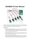
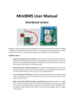
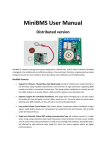
1. Install cell modules on each cell. Ring terminal attached to BMS board goes onto negative side of
the cell and red lead wire terminal goes on positive side. You MUST install BMS terminals on top
of copper links, but under the flat washer, to make sure it won’t be twisted when you torque the
terminal bolt. DO NOT install BMS terminals under copper links to avoid passing high currents
thru the BMS terminal. Thread both bolts by hand to secure both sides of BMS module before
tightening terminal bolts.
2. Using 18AWG – 16AWG wire and 0.25” Quick Disconnect crimp terminals fabricate wires to
connect all cells in one series string. Leave some slack on each wire to avoid stress if cells shift a
little during use. Signal connections are not polarized, so you can connect in any order, as long
as wire loop goes thru all cells and both ends meet at the head end control board.
WARNING: Push on connectors are very tight. With enough force when pushing connector
over the blade terminal you can lift the trace off the PCB and damage the connection. I
recommend loosening up the connector a little bit with flat screwdriver before pushing it
over the terminal.
3. Wire head end control board according to attached schematics. B+ terminal must come directly
from the 12V aux battery to ensure BMS is powered while ignition is off during charging. Ignition
(Key switch) input is required to reset BMS after each charge. When wiring to charger and motor
controller, please find most appropriate diagram for your type of charger and throttle assembly.
If you are not sure which diagram is best for you, contact MiniBMS support and provide models
of your charger, controller and throttle assembly to get detailed wiring directions.
4. You can use any 12v low current Buzzer from Radio Shack or other retailers. The more annoying
it is the more inclined the driver will be to react on LVC alerts, but it should not be deafening so
the driver can pay attention to the road. Mount the buzzer under the dash board or under the
steering wheel, so it can be heard clearly by the driver.
5. To test head end control board after it’s been wired, manually disconnect one of NC Loop wires,
simulating BMS alert condition. This should result in buzzer coming on after 5 second delay.
Delay is adjustable via trimpot on the head end control board. Delay is designed to filter out
false LVC alerts during brief voltage sags which are normal during hard accelerations. When NC