1
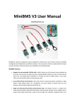
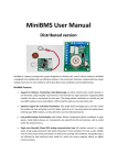
MiniBMS User Manual
Distributed version
MiniBMS is a battery management system designed for LiFePo4 cells, used in Electric Vehicles. MiniBMS
is designed to be reliable and cost effective solution; it has most basic functions, implemented via simple
analog circuit and one wire interface, which also allows easy installation and troubleshooting.
MiniBMS Features:
•
Support for all large prismatic LiFePo4 cells. Installs directly on cell terminals using included ring
terminals. One terminal has rigid connection supporting BMS module, the other is connected via
short wire. This design allows installation on virtually any cell size. BMS module is very small,
48mm x 30mm and fits easily on most prismatic cells.
•
Optional support for centralized installation, with single board managing up to 16 cells. Useful
for smaller cell sizes and packs, such as E-bikes, small cars, etc. You must select this option when
ordering your BMS modules, so they will not be cut into individual boards.
•
Low profile Printed Circuit Boards with Surface Mount Components allows installation in tight
spaces, inside battery boxes, etc. Components are sealed from dirt and moisture, safe to install
under the hood of the car.
•
Single wire Normally Closed (NC) analog communication loop. All modules connect in a single
series string using automotive style Quick Disconnect crimp terminals. NC loop is extra reliable
since it senses loose wiring connections as well as low and high cell conditions. Analog NC loop is
not affected by high electrical noise inside EV, which has severe negative effects on digital
communications.
•
Less than 7 mA operating current to prevent bleeding cells over long time period when not in
daily use. Resistors protect every part of the circuit from potential semiconductor failures. Any
component failure results in BMS alerts, protecting the battery even from BMS itself.
•
PTC resettable fuse protects from overheating during shunting as well as short circuit
conditions. Fuse opens if temp reaches 80C or if shunting current reaches 1 Amp. Open fuse
results in same alert as full charge, shutting down the charger. Fuse returns to normal conditions
automatically.
•
High Voltage Cutoff (HVC). HVC voltage level is selectable at the time of purchase for most
popular cell types. When first cell reaches HVC it will cause BMS to shut down the charger,
effectively protecting your battery pack. Since BMS can control AC power to the charger, you
can use practically any charger with this BMS, even “dumb” chargers without special LiFePo4
charging profiles. This requires purchase of high current solid state AC relay, not included with
BMS. If your charger has BMS shutoff input, then you don’t need AC relay. This datasheet is an
example of such AC relay http://www.teledynerelays.com/pdf/industrial/sh.pdf . You can find
many others from various online electronic parts retailers, including Ebay. Make sure you get a
relay rated for higher continuous currents than your charger pulls from AC outlet, so it doesn’t
get too hot. Still, you may need to mount it on a heat sink if it gets hot.
•
Low Voltage Cutoff (LVC) is temperature compensated. Each module has a thermistor which
automatically adjusts LVC for each cell, which works well if some cells are installed in different
locations in the car with different temperatures at each location. LVC is set to 2.5V at 0C temp,
2.6V at 25C temp and 2.7V at 50C temp, linearly adjusting itself across the entire temp range.
•
Green LED on each cell module indicates normal conditions, i.e. cell voltage is between LVC and
HVC levels. All cells must have Green LEDs on during normal use. When any cell goes below LVC
or above HVC levels, Green LED turns off and alert is created by open NC loop.
•
Optional shunt balancing has a maximum shunting current of 0.75 Amp. Red LED comes on
during shunting for visual indication. Shunting slows down charging process on cells reaching
HVC sooner than other cells, allowing other cells to catch up. This is referred to as “top
balancing”. Initial manual balancing is recommended, so BMS can keep the pack balanced long
term.
•
Head end control board is an interface between cell modules and charger and motor controller.
It uses simple NO/NC connections to act on LVC and HVC events. Control board senses alerts
from NC loop and acts on those by reducing the throttle ( LVC ) and shutting down the charger (
HVC ). Simple interface allows compatibility with virtually any charger and motor controller.
•
Head end control board supports piezo Buzzer to provide audible alarm for the driver when
alerts are triggered by cell modules. Any 12V low current buzzer from Radio Shack can be used.
MiniBMS Installation:
CRITICAL WARNING: Make sure your battery pack is physically disconnected from the rest
of your EV when attaching BMS modules to your cells. Failure to do so may result in last BMS
module completing the high voltage circuit before it gets attached to the last cell terminal.
This will damage the BMS module beyond repair and will not be covered by warranty!!!
1. Install cell modules on each cell. Ring terminal attached to BMS board goes onto negative side of
the cell and red lead wire terminal goes on positive side. You MUST install BMS terminals on top
of copper links, but under the flat washer, to make sure it won’t be twisted when you torque the
terminal bolt. DO NOT install BMS terminals under copper links to avoid passing high currents
thru the BMS terminal. Thread both bolts by hand to secure both sides of BMS module before
tightening terminal bolts.
2. Using 18AWG – 16AWG wire and 0.25” Quick Disconnect crimp terminals fabricate wires to
connect all cells in one series string. Leave some slack on each wire to avoid stress if cells shift a
little during use. Signal connections are not polarized, so you can connect in any order, as long
as wire loop goes thru all cells and both ends meet at the head end control board.
WARNING: Push on connectors are very tight. With enough force when pushing connector
over the blade terminal you can lift the trace off the PCB and damage the connection. I
recommend loosening up the connector a little bit with flat screwdriver before pushing it
over the terminal.
3. Wire head end control board according to attached schematics. B+ terminal must come directly
from the 12V aux battery to ensure BMS is powered while ignition is off during charging. Ignition
input is required to reset BMS after each charge. When wiring to charger and motor controller,
please find most appropriate diagram for your type of charger and throttle assembly. If you are
not sure which diagram is best for you, contact MiniBMS support and provide models of your
charger, controller and throttle assembly to get detailed wiring directions.
4. You can use any 12v low current Buzzer from Radio Shack or other retailers. The more annoying
it is the more inclined the driver will be to react on LVC alerts, but it should not be deafening so
the driver can pay attention to the road. Buzzer current should not exceed 250 mA, otherwise it
will trip the fuse on the control board. Mount the buzzer under the dash board or under the
steering wheel, so it can be heard clearly by the driver.
5. To test head end control board after it’s been wired, manually disconnect one of NC Loop wires,
simulating BMS alert condition. This should result in buzzer coming on after 2-4 second delay.
Delay is adjustable via trimpot on the head end control board. Delay is designed to filter out
false LVC alerts during brief voltage sags which are normal during hard accelerations. When NC
Loop connection is restored, buzzer should turn off immediately. It is not recommended to set
delay more than 4 seconds to prevent deep discharge during LVC events.
6. To test charger connection to BMS, after all charger connections are made, turn on the charger
and make sure it starts charging the pack normally. Ignition must be off at this time, so BMS can
expect HVC signal. Manually break NC Loop by disconnecting one of the wires. After 2-4 second
delay charger should turn off. When you restore NC Loop connection charger should remain in
off state until you cycle ignition key on and off.
7. It’s a bit more difficult to test BMS connection to motor controller since it requires running
motor to observe throttle reduction. If your EV is drivable, you can arrange to interrupt NC wire
loop from the cabin, using a temporary switch in line with NC wire loop to simulate LVC event.
After 2-4 second delay you should observe throttle reduction and buzzer alert. In real LVC event
throttle reduction will prolong your battery life so you can get off the road safely and prevent
damage to your battery pack.
MiniBMS Operation:
1. During charging Ignition key is off, which tells BMS to expect HVC event. When first cell reaches
HVC voltage BMS will interrupt NC loop and cause charger AC relay to interrupt power to the
charger. HVC event will latch on, so charger will not come back on when resting voltage goes
below HVC.
NOTE: In ideal world HVC function may not even interfere with the charger, allowing it to finish
CC/CV charging phases as intended by charger’s manufacturer. However, in case there enough
misbalance across multiple cells such that one cell gets to HVC much sooner than others, HVC
will protect the cell by cutting off charging process prematurely. It is up to you what action to
take depending on how prematurely HVC cutoff occurs. If charger is interrupted only a few
minutes before the end of CV phase, at which point charging current is very low, then you are
not losing much and you can simply let this happen every day. If you have BMS with shunting
option, then shunting process will over time pull back this pesky cell and equalize it with others.
Or, you can manually attempt to discharge that cell a little bit, to bring it down in line with
others. You have many choices and MiniBMS is here to protect your battery investment, even at
the cost of somewhat incomplete charge. You may soon realize that small amounts of charge at
the end of the charge cycle are not all that important and not worth risking overcharge of
individual cell.
2. You must disconnect the charger before turning Ignition on. Once ignition key is on, BMS will
reset HVC circuit to prepare it for the next charging cycle.
3. Once Ignition key is on BMS expects LVC events. During driving when your pack gets close to low
charge levels BMS will sense LVC events from cells with smallest capacity. This will initially
happen during heavy acceleration due to deeper voltage sag. 2-4 second delay is designed to
filter out brief voltage sags which may happen while there is still plenty of charge in the pack.
However, as you get closer to empty pack, LVC events will become more frequent and
prolonged, which is an indication to the driver to get off the road ASAP. If LVC alerts become
solid with little or no throttle applied, you have reached the lowest charge level and should not
drive anymore. It’s possible that one or two cells are damaged or have significantly lower
capacity than others, causing LVC alerts when you don’t expect them. Check Green LEDs on all
BMS modules to find offending cells, which will have Green LED turned off during LVC event.
4. Any lose wiring connections between cells and/or head end control board will also cause
LVC/HVC alerts to bring your attention, so you can find offending connection and fix it.
5. In a rare event when LVC alert is on solid you must keep the Ignition key on while turning on the
charger. This is necessary to prevent charger relay from false tripping since it can’t distinguish
LVC event from HVC event. Within few minutes all cells will climb over LVC voltage and you can
turn off ignition key and charger will remain running. This situation is an extreme case and
should never be experienced unless you ignore LVC alerts and run your pack to empty. DO NOT
leave the Ignition key on unattended while charging; it will disable BMS ability to turn off the
charger when first cell reaches HVC level.
MiniBMS Wiring Diagram:
This basic diagram shows how to interface MiniBMS with your battery pack, charger and motor
controller. This diagram shows motor controller with 2 wire resistive 0-5K pot box, which is common for
Curtis, Logisystems and some other controllers. 5K resistor shown in the diagram will be connected in
parallel to the pot box during LVC event, which will reduce total resistance to 2.5K, which effectively
clamps the throttle to 50% of max throttle. You can manipulate resistor value if you wish to clamp LVC
throttle to higher or lower levels. Keep in mind that getting off road safely should be higher priority than
saving few battery cells, don’t clamp the throttle too much so the car can keep driving at lower speeds.
Next diagram shows only motor controller portion of MiniBMS wiring diagram for 3 wire resistive pot box and
controller which expects 0-5V throttle input. Controllers which use this type of throttle input are Soliton1,
Kelly, and others. Check controller’s documentation for details. Do not use this diagram with Hall Effect
throttles, please refer to the following diagram for Hall Effect throttles.
If you are not sure which diagram works best for your conversion, please contact MiniBMS support for
assistance.
Next diagram shows only motor controller portion of MiniBMS wiring diagram for 3 wire Hall Effect throttle.
Since Hall Effect device is powered by 5V input, we must use voltage divider on the output side of the throttle
to reduce its output level during LVC event.
Below diagram shows how to interface LVC signal with popular Soliton1 and Soliton Jr. controllers from
EVNetics. These controllers have 3 programmable inputs, you can use any one of these inputs to interface
with BMS, then configure the input type in controller’s Web interface. BMS LVC input is ACTIVE LOW, so
normally BMS will pull it up to 12V using controller’s +12V signal supply via 5K resistor. When LVC event
occurs, BMS will pull the input down to Gnd, which will cause controller to reduce its power, using same
behavior as if the pack voltage reached low limit.
Optional charger controls: Some chargers have BMS input functions, which turn off the charger based on
ON/OFF or specific voltage input. You can wire such charger to MiniBMS control board without using high
power solid state AC relay. Please note that control board NO/NC output has 2 Amp commutation current
limits, if you exceed it you may damage the relay. Please check with MiniBMS support if you are not sure
about this option. See additional diagrams below for optional charger interface.
Auxillary 12V battery note: MiniBMS relies on constant power supplied from your 12V aux battery. Please
make sure your 12V battery is properly charged at all times to ensure correct BMS operation. For safety
reasons MiniBMS will shut off the charging process if it loses 12V power to the head end control board, which
may leave you with undercharged pack unexpectedly. MiniBMS takes less than 50 mA from 12V battery,
likely less than self discharge rate of typical Lead Acid battery, but any failure of the 12V battery will result in
BMS triggering HVC event, so your traction pack will still be protected from potential overcharge, even at the
cost of premature charger interruption.
LVC safety note: MiniBMS is designed to protect your battery pack from premature damage due to
overcharge and over discharge. Specifically LVC function is carefully designed not to interfere with normal
driving conditions until there is very little energy left in the pack. You should not let your pack get to LVC
alerts on regular basis and you should not rely on LVC alone to gauge your pack State Of Charge. Using
additional SoC instrumentation, such as voltmeter or special SoC gauge is highly recommended to avoid
reaching LVC levels on regular basis. Know your range limitations and plan your route, LVC is there to protect
your battery, even at the cost of leaving you stranded on the road. First LVC alerts will come under heavy
acceleration and indicate that you only have few minutes left to drive until your pack is empty.
Additional wiring diagrams for popular chargers with BMS Input.
NOTE: Manzanita chargers are not isolated, which can cause BMS damage
if charger is mounted to vehicle chassis. You must mount the charger on
non-conductive standoffs so charger body does not have electrical
contact with vehicle chassis.
This diagram is for new style Elcon PFC charger with 7 pin round
connector, which simply requires closure of Red/Green control wires to
enable the charger. Some older variations may have Red/Black wires,
which should work the same way.