1
DZB Series
Cha pter 6 Parameter D es cription
DZB Series
Chapter 6 Parameter Description
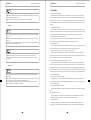
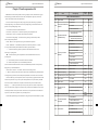
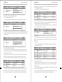
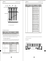
0: Terminal command inval id when power on. Inverte r will not run i f it detect operating command terminal
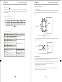
O u tp u t F r e q u e n c y f
i s valid. When t he operating command terminal is inval id and enable this ter minal again, inverter wi ll run.
1: Terminal command valid when power on. Inverter will startup aut omatically after initializat ion is
finished if i t det ect operation command terminal is vali d.
Note: Customer shou ld be careful when you select this fu nction, it may cause severe consequence.
T im e t
O u tp u t
V o lt a g e
F1 Motor Parameters
DCBrake
w h en
s ta r t in g
D C B ra k e
w h en
s to p p in g
T im e t
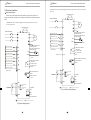
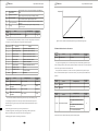
F ig. 6-3 DC Brake Diagram
Function
Code
F0.24
Setting Range
Name
Dead time between
forward and reverse
0.0 ~360.0s
Default
Value
0.0s
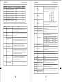
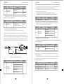
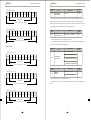
It is to set the transient ti me during which the output frequency i s 0 in the FWD/REV transient process
of inverter.
It is shown as following figure:
Output
Fre quency f
F orwar d
Functio n
Cod e
Setting Range
Name
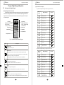
F1.00
Reserved
F1.0 1
Motor rated power
0.4~55 .0kW
F1.02
Motor rated frequency
0.0 1Hz~F0 .04
F1.0 3
Motor rated speed
0~ 9999rpm
F1.04
Motor rated voltage
0~ 460V
Default
Value
Set by
model
50.00Hz
Set by
model
Set by
model
Set by
model
Set by
model
S et by
model
F1.05
Motor rated current
0.1~10 0.0A
F1.06
Motor stator resistance
0.0 01~9.999Ω
F1.07
Motor rotor resistance
0.0 01~99.99Ω
F1.08
Motor stator/rotor
inductance
0.1~99 9.9mH
S et by
model
F1.09
Mutual inductance o f
motor stator/rotor
0.1~99 9.9mH
S et by
model
F1.10
No-l oad current
0.0 1~9 9.99A
S et by
model
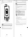
0 :NO operation
Time t
F1.11
Self-learning of
motor parameters
Re ver se
Dea d Time
Fig. 6-4 FWD/REV Dead Time Diagram
Function
Code
F0.25
Name
Terminal command
prote ction when
power on
Setting Range
Default
Value
0 :Terminal command invalid
wh en power on
1 :Terminal command valid when
power on
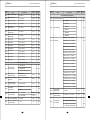
F1.12
Speed loop propor tional
ga in1
0~ 100
F1.1 3
Speed loop integral ti me1
0.0 1~1 0.00s
F1.14
Switching low
po int frequency
0.0 0Hz~F1 .1 7
F1.15
Speed loop propor tional
ga in 2
0~ 100
F1.16
Speed loop integral
time 2
0.0 1~1 0.00s
F1.17
Switching high
po int frequency
F1.14~99.99 Hz
F1.18
VC sl ip compensating
factor
50 %~2 00%
0
If operating command channel is set to terminal control, system wi ll detect t ermi nal status
aut omatica ll y duri ng inverter power on.
- 41-
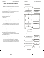
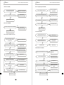
1 :comp lete tuning Self-learning
0
2 :static tuning Self-learning
-4 2 -
30
0.50s
5.00Hz
25
1.00s
10.00Hz
100%