1
K R A ME R E LE CT R O N IC S L TD .
USER MANUAL
MODEL:
VSM-4x4HFS
4x4 Seamless Matrix
Switcher/Multi-Scaler
P/N: 2900-300362 Rev 1
Contents
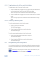
1
Introduction
1
2
2.1
2.2
2.3
3
3.1
Getting Started
Achieving the Best Performance
Safety Instructions
Recycling Kramer Products
Overview
Defining the VSM-4x4HFS 4x4 Seamless Matrix Switcher/Multi-Scaler
2
2
3
3
4
5
4
Installing in a Rack
8
5
5.1
5.2
5.3
5.4
6
6.1
6.2
6.3
6.4
6.5
6.6
7
Connecting and Operating the VSM-4x4HFS
The Matrix Mode
The Video Wall Mode
The Dual Mode
The QUAD Mode
Controlling the VSM-4x4HFS
Controlling via the Front Panel Buttons
Using the OSD Menu
Connecting to the VSM-4x4HFS via RS-232
Operating via Ethernet
Controlling via the Infrared Remote Control Transmitter
Using the IR Remote Control in the Dual Mode
Firmware Upgrade via USB
9
9
11
14
16
18
18
24
28
29
33
34
39
8
8.1
8.2
8.3
8.4
8.5
8.6
8.7
8.8
9
9.1
9.2
9.3
10
10.1
10.2
Using the Embedded Web Pages
Browsing the VSM-4x4HFS Web Pages
The Routing Page
The Device Settings Page
The Output Settings Page
The HDCP Settings Page
The EDID Page
The About Page
Save or Upload a Configuration
Technical Specifications
Default Communication Parameters
Table of Supported Input Resolutions
Table of Supported Output Resolutions
The VSM-4x4HFS RS-232 Communication Protocol
Protocol 3000
Kramer Protocol 3000 – Detailed Commands
40
40
41
49
52
53
54
56
56
57
57
58
58
59
59
63
Figures
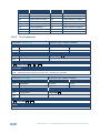
Figure 1: VSM-4x4HFS 4x4 Seamless Matrix Switcher/Multi-Scaler Front Panel
Figure 2: VSM-4x4HFS 4x4 Seamless Matrix Switcher/Multi-Scaler Rear Panel
Figure 3: Connecting the VSM-4x4HFS Presentation Switcher / Scaler
Figure 4: The VSM-4x4HFS Video Wall Operation Mode
Figure 5: Connecting the VSM-4x4HFS in the Video Wall Operation Mode
Figure 6: VSM-4x4HFS Bezel Correction
Figure 7: Connecting the VSM-4x4HFS in the Dual Operation Mode
6
7
10
11
12
13
15
VSM-4x4HFS – Contents
i
Figure 8: the VSM-4x4HFS QUAD Operation Mode Input Orientation
Figure 9: Connecting the VSM-4x4HFS in the Quad Operation Mode
Figure 10: Local Area Connection Properties Window
Figure 11: Internet Protocol Version 4 Properties Window
Figure 12: Internet Protocol Version 6 Properties Window
Figure 13: Internet Protocol Properties Window
Figure 14: Infrared Remote Control Transmitter
Figure 15: IR Remote Control Transmitter Dual Mode Shortcuts
Figure 16: The Routing Page
Figure 17: The Matrix Tab output Resolution
Figure 18: The Matrix Tab – Set the Output Resolution
Figure 19: The Matrix Tab – the Input Edit Window
Figure 20: The Matrix Tab – Type the new label
Figure 21: The Matrix Tab – View the Label
Figure 22: The Matrix Tab – Store a Configuration
Figure 23: The Matrix Tab – Recall a Configuration
Figure 24: The Video Wall Tab
Figure 25: The Video Wall Tab – Bezel Correction
Figure 26: The Dual Tab – POP Mode
Figure 27: The Dual Tab – PIP Mode
Figure 28: The Dual Tab – PIP Position
Figure 29: The Quad Tab
Figure 30: The Device Settings Page
Figure 31: The Device Settings Page – Ethernet Settings
Figure 32: The Device Settings Page – IP Number Settings
Figure 33: The Device Settings Page – the Information Window
Figure 34: The Device Settings Page – Factory Reset
Figure 35: The Output Settings Page – Output 1
Figure 36: The HDCP Settings Page
Figure 37: The EDID Page
Figure 38: The EDID Page – Copying the Native Timing
Figure 39: The EDID Page – Copying the Default
Figure 40: The EDID Page –The Copy EDID Results
Figure 41: The About Page
Figure 42: Loading a Configuration
ii
16
17
30
31
31
32
33
34
41
42
43
43
44
44
45
45
46
46
47
47
48
49
49
50
51
51
51
52
53
54
54
55
55
56
56
VSM-4x4HFS - Contents
1
Introduction
Welcome to Kramer Electronics! Since 1981, Kramer Electronics has been
providing a world of unique, creative, and affordable solutions to the vast range of
problems that confront video, audio, presentation, and broadcasting professionals
on a daily basis. In recent years, we have redesigned and upgraded most of our
line, making the best even better!
Our 1,000-plus different models now appear in 14 groups that are clearly defined by
function: GROUP 1: Distribution Amplifiers; GROUP 2: Switchers and Routers;
GROUP 3: Control Systems; GROUP 4: Format/Standards Converters; GROUP 5:
Range Extenders and Repeaters; GROUP 6: Specialty AV Products; GROUP 7:
Scan Converters and Scalers; GROUP 8: Cables and Connectors; GROUP 9:
Room Connectivity; GROUP 10: Accessories and Rack Adapters; GROUP 11:
Sierra Video Products; GROUP 12: Digital Signage; GROUP 13: Audio; and
GROUP 14: Collaboration.
Congratulations on purchasing your Kramer VSM-4x4HFS 4x4 Seamless Matrix
Switcher/Multi-Scaler.
This product, which incorporates HDMI™ technology, is ideal for:
Conference room presentations
Advertising applications, shopping malls and museums
Post production applications
Rental and staging
Security applications
Video-wall scaling
Applications with multiple inputs and outputs
Applications where quick, sleek, seamless switching is required
Any application requiring 4 scalers in a single 1RU rack space
VSM-4x4HFS – Introduction
1
2
Getting Started
We recommend that you:
Unpack the equipment carefully and save the original box and packaging
materials for possible future shipment
Review the contents of this user manual
i
2.1
Go to http://www.kramerelectronics.com/support/product_downloads.asp
to check for up-to-date user manuals, application programs, and to check
if firmware upgrades are available (where appropriate).
Achieving the Best Performance
To achieve the best performance:
Use only good quality connection cables (we recommend Kramer highperformance, high-resolution cables) to avoid interference, deterioration in
signal quality due to poor matching, and elevated noise levels (often
associated with low quality cables)
Do not secure the cables in tight bundles or roll the slack into tight coils
Avoid interference from neighboring electrical appliances that may
adversely influence signal quality
Position your Kramer VSM-4x4HFS away from moisture, excessive sunlight
and dust
!
2
This equipment is to be used only inside a building. It may only be
connected to other equipment that is installed inside a building.
VSM-4x4HFS - Getting Started
2.2
Safety Instructions
!
2.3
Caution:
There are no operator serviceable parts inside the unit
Warning:
Use only the power cord that is supplied with the unit
Warning:
Do not open the unit. High voltages can cause
electrical shock! Servicing by qualified personnel only
Warning:
Disconnect the power and unplug the unit from the wall
before installing
Recycling Kramer Products
The Waste Electrical and Electronic Equipment (WEEE) Directive 2002/96/EC aims
to reduce the amount of WEEE sent for disposal to landfill or incineration by
requiring it to be collected and recycled. To comply with the WEEE Directive,
Kramer Electronics has made arrangements with the European Advanced
Recycling Network (EARN) and will cover any costs of treatment, recycling and
recovery of waste Kramer Electronics branded equipment on arrival at the EARN
facility. For details of Kramer’s recycling arrangements in your particular country go
to our recycling pages at http://www.kramerelectronics.com/support/recycling/.
VSM-4x4HFS – Getting Started
3
3
Overview
The VSM-4x4HFS is a high−performance 4x4 Seamless Matrix Switcher/MultiScaler that allows switching between inputs via a clean video CUT (frame-to-frame
switching with no glitches). The VSM-4x4HFS can perform as a matrix switcher, a
2x2 video wall, and also features dual and quad multi-viewing options.
It supports HDMI resolutions with deep color and up to 8 channels of audio, and
supports per-port HDCP and EDID settings.
The VSM-4x4HFS features:
PixPerfect™ scaling technology – Kramer’s precision pixel mapping and
high quality scaling technology
HDTV compatibility
HDCP compliance – The HDCP (High Definition Content Protection) license
agreement allows copy−protected data on the HDMI input to pass only to the
HDMI outputs
4 HDMI inputs and four scaled HDMI outputs
Selectable operation modes – seamless matrix switcher, video wall, dual
display (Split/PIP/POP) or quad display
Bezel correction options – in the video wall mode
HDMI support for Deep Color, Dolby Digital Plus, DTS, DTS−HD®, LPCM
2CH/6CH/8CH, AC3
HDCP and EDID settings per port
VGA to WUXGA and 480i to 1080p Input resolution range
480p to 1080p Output resolution range
Multiple aspect ratio selections - full, 4:3, 16:9 and best fit
Built-in ProcAmp - color, hue, sharpness, noise, contrast and brightness
Front panel control – operation mode, TAKE button, and menu buttons
4 preset memory locations for each operation mode for quick access to
common IN-OUT configurations
4
VSM-4x4HFS - Overview
Front panel lockout
Non-volatile memory – saves final settings
Program mini USB connector for firmware upgrade
Control your VSM-4x4HFS:
Directly, via the front panel push buttons
By RS-232 serial commands transmitted by a touch screen system, PC, or
other serial controller
Remotely, from the infrared remote control transmitter with OSD (on-screen
display)
Via the Ethernet with built-in Web pages
The VSM-4x4HFS is housed in a 19” 1U rack mountable enclosure, with rack
“ears” included, and is fed from a 100-240 VAC universal switching power supply.
3.1
Defining the VSM-4x4HFS 4x4 Seamless Matrix
Switcher/Multi-Scaler
This section defines the VSM-4x4HFS.
VSM-4x4HFS – Overview
5
6
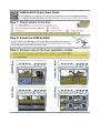
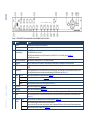
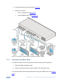
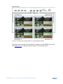
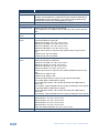
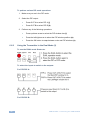
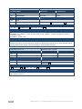
Figure 1: VSM-4x4HFS 4x4 Seamless Matrix Switcher/Multi-Scaler Front Panel
#
Feature
Function
1
IR LED
Lights when the unit accepts IR remote commands
IR Receiver
Receives signals from the remote control transmitter
2
OUTPUT/WINDOW
Selector Buttons
In the MATRIX mode: select the output to which the input is switched (A, B, C or D)
In the VIDEO WALL mode: not used
In the DUAL mode: select one of the two DUAL windows (A or B for DUAL A; C or D for DUAL B), see Section 5.3
In the QUAD mode: not used
3
INPUT Selector Buttons
Press to select an HDMI input (from 1 to 4) to switch to the output
4
ALL Button
Press ALL followed by an INPUT button to connect that input to all the outputs (not available for the video wall mode)
5
OFF Button
Press after pressing an output button to disconnect the selected output from the inputs. To disconnect all the outputs, press ALL followed
by OFF
6
TAKE Button
Press to toggle between the Confirm mode (when in the Confirm mode, the TAKE button lights ) and the At Once mode. When in TAKE
mode, front panel buttons actions are implemented after pressing the TAKE button (see Section 6.1.2)
7
MODE
Buttons
MATRIX
Press to operate the system as a matrix switcher (see Section 5.1)
VIDEO WALL
Press to operate as a 2x2 video wall (see Section 5.2)
9
DUAL
Press to operate as a 4x2 switcher with PIP capabilities (see Section 5.3)
10
QUAD
Press to display all four inputs on each of the outputs (see Section 5.4)
8
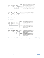
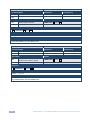
VSM-4x4HFS – Overview
11
STO Button
Press to store a configuration (see Section 6.1.3)
12
RCL Button
Press to recall a configuration (see Section 6.1.3)
13
IDENTIFY Button
Press to indicate on each output, which input is displayed on the output. The display time is set via the OSD menu (see Section 6.2.1)
14
MENU
Press to access the OSD menu, exit the OSD menu and, when in the OSD menu, move to the previous level in the OSD screen (see
Section 6.1.2)
15
Navigation
Buttons
ENTER
Press to access sub-menu items and select from several settings (see Section 6.1.2)
Press to decrease numerical values or select from several definitions
When not within the OSD menu mode, press to reduce volume (for embedded HDMI inputs, this does not affect the embedded output)
Press to move up the menu list values (see Section 6.1.2)
VSM-4x4HFS – Overview
#
Feature
Function
Press to increase numerical values or select from several definitions
When not within the OSD menu mode, press to increase volume (for embedded HDMI inputs, this does not affect the embedded output)
Press to move down the menu list (see Section 6.1.2)
16
RESET TO XGA/720p
Button
Press and hold for about 4 seconds to toggle resetting the video resolution to XGA or 720p I
17
PANEL LOCK Button
Press and hold for about 2 seconds to lock/unlock the front panel buttons
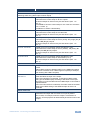
Figure 2: VSM-4x4HFS 4x4 Seamless Matrix Switcher/Multi-Scaler Rear Panel
#
18
Feature
INPUT HDMI Connectors
Connect to the HDMI sources (from 1 to 4)
Function
19
OUTPUT HDMI Connectors
Connect to the HDMI acceptors (from A to D); DUAL: when in the dual operation mode, A, A and B, B
20
ETHERNET Connector
Connects to the PC or other Serial Controller through computer networking
21
PROG USB Connector
Connect to upgrade the unit
22
RS-232 9-pin D-sub Port
Connect to the PC or a remote controller
23
Mains Socket
Connect the mains power cord
24
Mains Fuse Holder
Fuse for protecting the device
25
Power Switch
Switch for turning the unit ON or OFF
7
4
Installing in a Rack
This section provides instructions for rack mounting the unit.
8
VSM-4x4HFS - Installing in a Rack
5
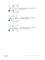
Connecting and Operating the VSM-4x4HFS
The VSM-4x4HFS is a four-in-one-box device. It can operate as a:
Matrix switcher
Video wall
Dual switcher
Quad switcher
You can select the different operation modes via front panel buttons, the IR remote
control transmitter, the OSD menu or via the Web pages.
This section describes how to connect and operate the VSM-4x4HFS for operating
in each of the four operation modes (see Section 5).
!
i
5.1
Always switch off the power to each device before connecting it to
your VSM-4x4HFS. After connecting your VSM-4x4HFS, connect
its power and then switch on the power to each device.
You do not have to connect all the inputs and outputs, connect only
those that are required.
The Matrix Mode
The VSM-4x4HFS matrix switcher mode is the default operation mode. Any of the
four inputs can be switched to any of the four outputs. Switching is immediate and
seamless.
5.1.1
Connecting the VSM-4x4HFS in the Matrix Operation Mode
To connect the VSM-4x4HFS in the MATRIX mode, as illustrated in the example in
Figure 3, do the following:
1. Connect up to four HDMI sources (for example, laptops and/or Blu-ray disk
players) to the HDMI INPUT connectors (from INPUT 1 to INPUT 4).
2. Connect the four HDMI OUTPUT connectors (from OUTPUT A to OUTPUT
D) to up to four HDMI acceptors (for example, LCD displays and/or
projectors).
VSM-4x4HFS - Connecting and Operating the VSM-4x4HFS
9
3. Connect the power cord (not shown in Figure 3).
4. If required, connect:
A PC via RS-232, see Section 6.3
The ETHERNET port, see Section 6.4
Figure 3: Connecting the VSM-4x4HFS Presentation Switcher / Scaler
5.1.2
Operating in the Matrix Mode
To select the inputs via the front panel buttons/IR remote control transmitter:
1. Select the Matrix operation mode.
2. Press an output and then an input to switch to the selected output.
You can also switch several inputs and outputs using the TAKE button (see Section
6.1.2).
10
VSM-4x4HFS - Connecting and Operating the VSM-4x4HFS
5.2
The Video Wall Mode
The video wall mode lets you display the output on a set of four monitors /
projectors / TV sets that are tiled together in a 2x2 setting to form one large display.
Each output shows one quarter of the image as shown in the example in Figure 4.
In the video wall mode the audio of the selected input is routed to one of the
outputs.
Figure 4: The VSM-4x4HFS Video Wall Operation Mode
5.2.1
Connecting the VSM-4x4HFS in the Video Wall Operation Mode
To connect the video wall as illustrated in Figure 5, do the following:
1. Connect an HDMI source (for example, a Blu-ray disk player) to the INPUT 1
connector (you can connect up to four input connectors), not shown in Figure 5.
2. Connect the HDMI output connectors to the video wall screens. Connect the:
OUTPUT A connector to the top left screen
OUTPUT B connector to the top right screen
OUTPUT C connector to the bottom left screen
OUTPUT D connector to the bottom right screen
3. Connect the power cord (not shown in Figure 5).
4. If required, connect:
A PC via RS-232, see Section 6.3
The ETHERNET port, see Section 6.4
VSM-4x4HFS - Connecting and Operating the VSM-4x4HFS
11
Figure 5: Connecting the VSM-4x4HFS in the Video Wall Operation Mode
5.2.2
Operating in the Video Wall Mode
To select the inputs via the front panel buttons/IR remote control transmitter:
1. Select the Video Wall operation mode.
2. Press an input to switch to the output.
12
VSM-4x4HFS - Connecting and Operating the VSM-4x4HFS
5.2.3
Bezel Correction
You can use bezel correction via the OUTPUT menu (see Section 6.2.1) to make
up for the rims around the displays used for creating the video wall, thus creating
one smooth picture. In the example in Figure 6 the top photo shows the video wall
before bezel connection and the lower photo shows the corrected image on the
video wall.
Figure 6: VSM-4x4HFS Bezel Correction
VSM-4x4HFS - Connecting and Operating the VSM-4x4HFS
13
5.3
The Dual Mode
In the Dual operation mode the VSM-4x4HFS is set as a 4x2 switcher with picture-inpicture capabilities that outputs two identical A outputs and two identical B outputs
(see Figure 7).
The dual outputs display any two selected input signals together on one screen.
The OSD/IR remote control transmitter/Web pages lets you set the DUAL mode to
the POP (side-by-side) or PIP (picture-in-picture) mode.
5.3.1
Connecting the VSM-4x4HFS in the Dual Operation Mode
To connect in the Dual mode as illustrated in Figure 7, do the following:
1. Connect an HDMI source (for example, a Blu-ray disk player) to the INPUT 1
connector (from 1 to 4), not shown in Figure 7.
2. Connect the HDMI output connectors as follows. Connect the:
DUAL A connector to an HDMI acceptor (for example, an LCD display)
DUAL A connector to an HDMI acceptor (for example, an LCD display)
DUAL B connector to an HDMI acceptor (for example, an LCD display)
DUAL B connector to an HDMI acceptor (for example, an LCD display)
Note that you do not have to connect all the outputs.
3. Connect the power cord (not shown in Figure 7).
4. Setup the system (see Section 5.3)
5. If required, connect:
14
A PC via RS-232, see Section 6.3
The ETHERNET port, see Section 6.4
VSM-4x4HFS - Connecting and Operating the VSM-4x4HFS
Figure 7: Connecting the VSM-4x4HFS in the Dual Operation Mode
Note that in this example “Show” is selected in the BORDER menu item (see
Section 6.2.1) to display all the borders.
5.3.2
Operating in the Dual Mode
To select the inputs via the front panel buttons/IR remote control transmitter:
1. Select the DUAL operation mode.
2. Select one of the dual outputs (A: A or B; B: C or D).
3. Select any two inputs: the first selection would be the LEFT (POP mode) or
the MAIN (PIP mode) image and the second would be the RIGHT (POP
mode) or the PIP (PIP mode) image.
To select the inputs via the OSD, use the SOURCE menu item (see Section 6.2.1).
To select the inputs via the IR remote control transmitter, see Section 6.6.
VSM-4x4HFS - Connecting and Operating the VSM-4x4HFS
15
5.4
The QUAD Mode
The QUAD view shows any four inputs on one screen (each quarter of a screen
can show any selected input) and outputs it identically to all four outputs (OUTPUT
A to OUTPUT D). Figure 8 shows the order in which the outputs are set in the
QUAD mode (this order cannot be configured):
Figure 8: the VSM-4x4HFS QUAD Operation Mode Input Orientation
5.4.1
Connecting the VSM-4x4HFS in the Quad Operation Mode
To connect the VSM-4x4HFS in the QUAD mode as illustrated in Figure 9, do the
following:
1. Connect an HDMI source to up to four inputs (for example, a Blu-ray disk
player) to the INPUT 1 connector (from 1 to 4), not shown in Figure 9.
2. Connect the HDMI output connectors OUTPUT A, OUTPUT B, OUTPUT C
and OUTPUT D to an HDMI acceptor (for example, to LCD displays).
Note that you do not have to connect all the outputs
3. Connect the power cord (not shown in Figure 9).
4. If required, connect:
A PC via RS-232, see Section 6.3
The ETHERNET port, see Section 6.4
All four inputs are displayed on each output.
16
VSM-4x4HFS - Connecting and Operating the VSM-4x4HFS
Figure 9: Connecting the VSM-4x4HFS in the Quad Operation Mode
Note that in this example “Only Selected” is selected in the BORDER menu item
(see Section 6.2.1) to display only the border of the selected output.
VSM-4x4HFS - Connecting and Operating the VSM-4x4HFS
17
6
Controlling the VSM-4x4HFS
The VSM-4x4HFS can be controlled via:
The front panel buttons (see Section 6.1)
The OSD menu (see Section 6.2)
RS-232 serial commands transmitted by a touch screen system, PC, or
other serial controller (see Section 6.3)
6.1
The ETHERNET (see Section 6.4), via the Web Pages
The infrared remote control transmitter (see Section 6.5)
Controlling via the Front Panel Buttons
The VSM-4x4HFS includes the following front panel buttons:
Input selector buttons for selecting the required INPUT, HDMI (1 to 4) and
OUTPUT/WINDOW selector buttons (A to D)
ALL (to connect a selected input to all the outputs) and OFF (to disconnect a
selected output from the inputs) buttons
MODE buttons: MATRIX, VIDEO WALL, DUAL and QUAD
STO and RCL buttons
A TAKE button
An IDENTIFY button to identify the inputs connected to the outputs
MENU, ENTER, and up, down, left and right arrow buttons to for the OSD
menu
18
RESET TO XGA/720p and PANEL LOCK buttons
VSM-4x4HFS - Controlling the VSM-4x4HFS
6.1.1
Switching Inputs to Outputs
The switching procedures are different for each of the four operation modes. Note
that incomplete operations on the VSM-4x4HFS timeout after 15 seconds.
Matrix Mode
To switch an input to an output in the Matrix mode:
1. Press the required OUTPUT/WINDOW button.
The selected button illuminates.
2. Press an INPUT button to select the input to switch to the output.
You can also switch several inputs and outputs using the TAKE button (see Section
6.1.2).
Video Wall Mode
To switch an input to the output, press an input button (from 1 to 4). The selected
image appears on the video wall.
The audio input signal is routed to one of the four displays.
Dual Mode
POP Mode: select the inputs to switch to the LEFT and RIGHT images for each of
the two dual groups (two A outputs and two B outputs).
PIP Mode: select the inputs to switch to the MAIN and PIP images for each of the
two dual groups (two A outputs and two B outputs).
To select the images for group A (POP/PIP) using the front panel buttons:
1. Press OUTPUT A (or OUTPUT B).
The selected button illuminates.
2. Press an INPUT button (from 1 to 4) to select the left/main image on the
output.
3. Press an INPUT button (from 1 to 4) to select the right/PIP image on the
output.
VSM-4x4HFS - Controlling the VSM-4x4HFS
19
To select the images for group B (POP/PIP) using the front panel buttons:
1. Press OUTPUT C (or OUTPUT D).
The selected button illuminates.
2. Press an INPUT button (from 1 to 4) to select the left/main image on the
output.
3. Press an INPUT button (from 1 to 4) to select the right/PIP image on the
output.
The audio signal of the input selected first (the left/main image) will be routed to the
output.
QUAD Mode
In the QUAD mode there are no input/output switching operations since all the
inputs appear on each output in a preset order.
6.1.1.1 Switching an Input to all Outputs
This feature is available for all operation modes except the video wall mode
To switch an input to all the outputs:
1. Press the ALL button.
2. Press an INPUT button to select the input to switch to all outputs.
The selected input is switched to all outputs.
6.1.1.2 Disconnecting an Input from an Output
To disconnect an input from an output:
1. Press the required OUTPUT button.
The selected output Illuminates.
2. Press the OFF button.
The selected output is disconnected.
20
VSM-4x4HFS - Controlling the VSM-4x4HFS
6.1.1.3 Disconnecting all the Inputs from the Outputs
This feature is available for all operation modes except the video wall mode.
To disconnect all the inputs from the outputs:
1. Press the ALL button.
2. Press the OFF button.
All the inputs are disconnected from all the outputs.
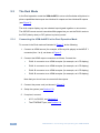
6.1.2
The TAKE Button
You can choose to work in the At Once or the Confirm mode. When the
VSM-4x4HFS operates in the At Once mode, pressing an output-input combination
implements the action immediately. In the Confirm mode, the TAKE button must be
pressed to activate the switch.
The At Once Mode
In the At Once mode, execution is immediate and actions require no user
confirmation. However, no protection is offered against changing an action in error.
The Confirm Mode
In the Confirm mode:
You can enter several actions and then confirm them by pressing the TAKE
button to simultaneously activate the multiple switches
Every action requires user confirmation which protects against erroneous
switching
Execution is delayed until the user confirms the action
Note that if the TAKE button is not pressed within 60 seconds, this action is aborted
VSM-4x4HFS - Controlling the VSM-4x4HFS
21
6.1.2.1 Toggling between the At Once and Confirm Modes
To toggle between the At Once and Confirm modes:
1. Press the TAKE button to toggle from the At Once mode (the TAKE button is
not illuminated) to the Confirm mode (the TAKE button lights).
Actions now require user confirmation and the TAKE button lights.
2. Press the TAKE button to toggle from the Confirm mode back to the At Once
mode.
Actions no longer require user confirmation and the TAKE button no longer
lights.
6.1.2.2 Confirming a Switching Action
To confirm a switching action (in the Confirm mode):
1. Press an output-input combination.
The TAKE button flashes.
2. Press the flashing TAKE button to confirm the action.
The TAKE button lights.
To confirm several switching actions (in the Confirm mode):
1. Press each OUTPUT-INPUT combination in sequence.
The TAKE button flashes.
2. Press the flashing TAKE button to confirm all the actions.
The TAKE button lights.
6.1.3
Storing/Recalling In/Out Configurations
You can store and recall up to four input/output configuration setups per operation
mode via the four INPUT buttons. The stored setups are saved in the non-volatile
memory.
i
22
Note that you can also store and recall a setup via the OSD menu (see
Section 6.2.1) and the Web pages (see Section 7).
VSM-4x4HFS - Controlling the VSM-4x4HFS
6.1.3.1 Storing an Input/Output Configuration
To store the current status in memory, do the following:
1. Press the STO button.
The STO button lights.
2. Press one of the INPUT buttons (this will be the setup # in which the current
status is stored). If in the Confirm mode, press the blinking TAKE button to
confirm the action.
The memory stores the data at that reference.
6.1.3.2 Recalling an In/Out Configuration
To recall an input/output configuration, do the following:
1. Press the RCL button.
The RCL button lights.
2. Press the appropriate INPUT button (the button # corresponding to the setup
#). If in the Confirm mode, that setup configuration will only be implemented
after pressing the TAKE button.
The memory recalls the stored data from that reference.
6.1.4
Front Panel Button Shortcuts
This section defines several front panel button shortcuts:
Selecting an audio source – press and hold (for 3 seconds) an output
(OUTPUT A to OUTPUT D) to select the audio source
Muting the audio output – press and hold (for 3 seconds) the ALL button
to toggle between muting (blocking out the sound) and enabling the audio
output
Resetting the machine – press the MENU Button while plugging the power
to reset the machine
VSM-4x4HFS - Controlling the VSM-4x4HFS
23
6.2
Using the OSD Menu
The control buttons let you control the VSM-4x4HFS via the OSD menu. Press the:
MENU button to enter the menu
The default timeout is set to 10 seconds
ENTER button to accept changes and to change the menu settings
Arrow buttons to move through the OSD menu, which is displayed on the
video output
On the OSD menu, select EXIT to exit the menu.
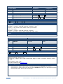
6.2.1
The OSD MENU
Mode
MODE
Function
MATRIX
Select the 4x4 matrix switcher mode
VIDEO WALL
Select the 2x2 video wall mode
DUAL POP
Select the 4x2 dual POP operation mode: both A outputs display two
selected inputs that appear as side by side images identically. In the
same way both B outputs display two selected inputs that appear as side
by side images identically
DUAL PIP
Select the 4x2 dual PIP operation mode: both A outputs display two
selected inputs that appear as one PIP image over a main screen image,
identically. In the same way, both B outputs display two selected inputs
that appear as one PIP image over a main screen image, identically
QUAD
Select the QUAD operation mode: All four outputs show all the four input
images each of which appears on one quarter of the screen
EXIT
Exit the MODE menu
PICTURE
Note that the PICTURE menu changes in accordance with the operation mode
24
In MATRIX Mode
Set the CONTRAST, BRIGHTNESS, SATURATION and HUE on all the
outputs
RESET ALL the PICTURE parameters to their default values
In VIDEO WALL
Mode
Set the CONTRAST, BRIGHTNESS, SATURATION and HUE separately
for OUT A, OUT B, OUT C and OUT D.
RESET each parameter for all the outputs
RESET ALL the PICTURE parameters to their default values
In DUAL POP
Mode
Set the CONTRAST, BRIGHTNESS, SATURATION and HUE separately
for the LEFT and RIGHT images of the A outputs, and the LEFT and
RIGHT images of B outputs.
RESET each parameter for all the outputs
RESET ALL the PICTURE parameters to their default values
In DUAL PIP
Mode
Set the CONTRAST, BRIGHTNESS, SATURATION and HUE separately
for the MAIN and PIP images of the A outputs and the MAIN and PIP
images of B outputs.
RESET each parameter for all the outputs
RESET ALL the PICTURE parameters to their default values
VSM-4x4HFS - Controlling the VSM-4x4HFS
Mode
In QUAD Mode
Function
Set the CONTRAST, BRIGHTNESS, SATURATION and HUE separately
for QUAD 1, QUAD 2, QUAD 3 and QUAD 4.
RESET each parameter for all the QUADs
RESET ALL the PICTURE parameters to their default values
EXIT
Exit the PICTURE menu
OUTPUT
RESOLUTION
Set the output resolution to NATIVE , 480p, 576p, 720p50, 720p60,
1080p24, 1080p50, 1080p60, 1024x768, 1280x800, 1280x1024,
1366x768, 1440x900, 1600x900, 1600x1200, 1680x1050 or 1920x1200
Note NATIVE resolution is read from OUT A. If the FW cannot detect the
OUT A native resolution or if it is not supported, the resolution defaults to
720p60
ASPECT RATIO
Set to Full, 4:3, 16:9 or Best Fit
BORDERS
Available only for the DUAL and QUAD operation modes
Set to Show (all the borders), Only Selected (only the selected output) or
OFF
If Show is selected (a border around each image), the selected output’s
border will appear thicker
BORDER COLOR Select RED, GREEN, BLUE, YELLOW, MAGENTA or GREY
INPUT LABELS
Set input labels to ON or OFF
By default the label is set to Source 1 for input 1, Source 2 for input 2 and
so on.
Note that the labels can be changed via the Web pages or RS-232
commands
OUTPUT LABELS Set output labels to ON or OFF (for MATRIX mode only)
By default, labels are set to Output1, Output 2 and so on.
Note that the labels can be changed via the Web pages or RS-232
commands
BEZEL
CORRECTION
In the Video Wall operation mode, use bezel correction to compensate for
the video wall monitor rims which create a non-continuous image across
the video wall
Set to OFF or ON for the Video Wall operation mode only
H BEZEL
CORRECTION
Set the horizontal bezel correction
Note that output resolutions 480p and 576p do not support bezel
correction
V BEZEL
CORRECTION
Set the vertical bezel correction
Note that output resolutions 480p and 576p do not support bezel
correction
IDENTIFY
Identify each input/output as well as the audio source (for DUAL and
QUAD modes)
EXIT
Exit the OUTPUT menu
EDID
INPUT 1
Set the output from which the EDID is read to input 1: OUT A, OUT B,
OUT C, OUT D, Default or FILE
INPUT 2
Set the output from which the EDID is read to input 2: OUT A, OUT B,
OUT C, OUT D, Default or FILE
INPUT 3
Set the output from which the EDID is read to input 3: OUT A, OUT B,
OUT C, OUT D, Default or FILE
INPUT 4
Set the output from which the EDID is read to input 4: OUT A, OUT B,
OUT C, OUT D, Default or FILE
Note that EDID does not support 4k2k and 3D
VSM-4x4HFS - Controlling the VSM-4x4HFS
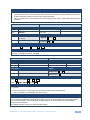
25
Mode
Function
The FILE option is set from the Web pages (see Section 8.6)
AUDIO EDID
Set the audio format to LPCM 2CH (accepts LPCM 2CH), LPCM 6CH
(accepts LPCM 2CH/6CH), LPCM 8CH (accepts LPCM 2CH/6CH/8CH),
BITSTREAM ((accepts LPCM 2CH, AC3, DTS) or HD (accepts LPCM
2CH/6CH/8CH, AC3, DTS, Dolby Digital Plus, DTS-)
EXIT
Exit the EDID mode
SOURCE
26
In MATRIX Mode
Set the input source for each of the outputs:
From VIDEO OUT A to VIDEO OUT D, select IN 1, IN 2, IN 3 or IN 4 for
each
In VIDEO WALL
Mode
Select the video wall input source
In DUAL POP
Mode
Select the input sources for the left and right sides of outputs A and the
left and right sides of outputs B:
VIDEO OUT A LEFT: IN 1, IN 2, IN 3 or IN 4
VIDEO OUT A RIGHT: IN 1, IN 2, IN 3 or IN 4
VIDEO OUT B LEFT: IN 1, IN 2, IN 3 or IN 4
VIDEO OUT B RIGHT: IN 1, IN 2, IN 3 or IN 4
Set the audio source for outputs A and outputs B (left or right for each
set):
AUDIO OUT A: LEFT or RIGHT
AUDIO OUT B: LEFT or RIGHT
In DUAL PIP
Mode
Select the input sources for the MAIN and PIP sides of outputs A and the
MAIN and PIP sides of outputs B:
VIDEO OUT A MAIN: IN 1, IN 2, IN 3 or IN 4
VIDEO OUT A PIP: IN 1, IN 2, IN 3 or IN 4
VIDEO OUT B MAIN: IN 1, IN 2, IN 3 or IN 4
VIDEO OUT B PIP: IN 1, IN 2, IN 3 or IN 4
Set the audio source for outputs A and outputs B (MAIN or PIP for each
set):
AUDIO OUT A: MAIN or PIP
AUDIO OUT B: MAIN or PIP
Set the PIP parameters for outputs A and outputs B separately:
PIP A SIZE: SMALL, MEDIUM or LARGE
PIP A POSITION: RIGHT TOP, RIGHT BOTTOM, LEFT BOTTOM or
LEFT TOP
PIP A SWAP: swap the MAIN and PIP images (including the audio signal)
PIP B SIZE: SMALL, MEDIUM or LARGE
PIP B POSITION: RIGHT TOP, RIGHT BOTTOM, LEFT BOTTOM or
LEFT TOP
PIP B SWAP: swap the MAIN and PIP images (including the audio signal)
In QUAD Mode
Set the input source for each QUAD:
VIDEO QUAD 1: IN 1, IN 2, IN 3 or IN 4
VIDEO QUAD 2: IN 1, IN 2, IN 3 or IN 4
VIDEO QUAD 3: IN 1, IN 2, IN 3 or IN 4
VIDEO QUAD 4: IN 1, IN 2, IN 3 or IN 4
Select the AUDIO SOURCE: IN 1, IN 2, IN 3 or IN 4
EXIT
Exit the source mode
VSM-4x4HFS - Controlling the VSM-4x4HFS
Mode
RECALL/STORE
Function
The STORE/RECALL setups are defined separately for each operation mode and include the
switching status only (which input to which output)
In MATRIX Mode
STORE up to four input/output setups and RECALL them.
NOW shows the current setup for all four outputs
The stored setups for each memory are also shown (FAV. 1 to
FAV. 4).
Use STORE to store the current setup to one of the four memories
(FAV. 1 to FAV. 4)
Use RECALL to select a stored setup.
In VIDEO WALL Mode
STORE up to four input setups and RECALL them.
NOW shows the current setup for the video wall
The stored setups for each memory are also shown (FAV. 1 to
FAV. 4).
In DUAL POP Mode
STORE up to four input/output setups and RECALL them.
NOW shows the current setup for the AL (A left), AR (A right), BL (B
left) and BR (B right) outputs.
The stored setups for each memory are also shown (FAV. 1 to
FAV. 4)
In DUAL PIP Mode
STORE up to four input/output setups and RECALL them.
NOW shows the current setup for the AL (A Main), AR (A PIP), BL
(B Main) and BR (B PIP) outputs.
The stored setups for each memory are also shown (FAV. 1 to
FAV. 4)
In QUAD Mode
STORE up to four input/output setups and RECALL them.
NOW shows the current setup for each QUAD (1 to 4).
The stored setups for each memory are also shown (FAV. 1 to
FAV. 4)
HDCP
INPUT 1 to INPUT 4
Select the HDCP option for the HDMI input: either ON (the default)
or OFF:
Setting HDCP support to disabled (OFF) on the HDMI input allows
the source to transmit a non-HDCP signal if required (for example,
when working with a Mac computer)
OUTPUT A to
OUTPUT D
Select FOLLOW INPUT or FOLLOW OUTPUT to define whether the
HDCP will follow the input or the output
When FOLLOW INPUT is selected, it changes its HDCP output
setting (for the HDMI output) according to the HDCP of the input.
This option is recommended when the HDMI output is connected to
a splitter/switcher
When FOLLOW OUTPUT is selected, the scaler matches its HDCP
output to the HDCP setting of the HDMI acceptor to which it is
connected
AUTO-SYNC OFF
Turn the auto sync ENABLE or DISABLE. When enabled, this
de-activates the output after 2 minutes if no input is present.
This is useful, for example, when the output is connected to a
projector, and the projector will automatically shut down when it has
no input
VSM-4x4HFS - Controlling the VSM-4x4HFS
27
Mode
OSD SETTINGS
Function
POSITION
Set the position of the OSD to LEFT TOP, RIGHT TOP, LEFT
BOTTOM or RIGHT BOTTOM
H OFFSET
Shift the horizontal position of the OSD
V OFFSET
Shift the vertical position of the OSD
VIDEO WALL OSD
Set to SINGLE OUTPUT to have the OSD appear on one of the
video wall outputs or set to All Outputs to have the OSD appear on
all four outputs.
TRANSPARENCY
Set the OSD background between 9 (opaque) and 0 (transparent)
IDENT. TIMEOUT
Set the “Identify” label timeout period in seconds or set it to OFF so
it will appear continuously
MENU TIMEOUT
Set the menu timeout period in seconds or set it to OFF so it will
appear continuously
INFO. TIMEOUT
Set the “INFO” display timeout period in seconds or set it to OFF so
it will appear continuously
INFO. DISPLAY
Set the display of information ON or OFF
BRIEF INFO
Set the display of brief information ON or OFF
EXIT
Click to exit this menu
ETHERNET
IP MODE
Set to DHCP or STATIC
STATIC SET
Set to IP number, NETmask or GATEway to change their numerals
BYTE (1 to 4)
Set the IP, NET and GATE addresses via these 4 bytes
By default: IP = 192.168.1.39; Gateway = 192.168.1.254; and
Netmask = 255.255.255.0
RELINK
Select to re-link the system after setup
EXIT
Exit the Ethernet menu
NOW
Shows the link status and the current IP, MASK and GATE
addresses
FACTORY DEFAULT
Select NO or YES to reset to the factory default parameters
(including the Ethernet parameters)
INFORMATION
Displays the IN/OUT resolution, the source DHCP, source audio
format, OUT A native resolution, OUT mode, Ethernet MAC,
Firmware version and the Kramer LOGO
EXIT
Click to exit the main menu
6.3
Connecting to the VSM-4x4HFS via RS-232
You can connect to the VSM-4x4HFS via an RS-232 connection using, for example,
a PC. Note that a null-modem adapter/connection is not required.
To connect to the VSM-4x4HFS via RS-232, connect the RS-232 9-pin D-sub rear
panel port on the product unit via a 9-wire straight cable (only pin 2 to pin 2, pin 3 to
28
VSM-4x4HFS - Controlling the VSM-4x4HFS
pin 3, and pin 5 to pin 5 need to be connected) to the RS-232 9-pin D-sub port on
your PC.
6.4
Operating via Ethernet
You can connect to the VSM-4x4HFS via Ethernet using either of the following
methods:
Directly to the PC using a crossover cable (see Section 6.4.1)
Via a network hub, switch, or router, using a straight-through cable (see
Section 6.4.2)
Note: If you want to connect via a router and your IT system is based on IPv6,
speak to your IT department for specific installation instructions.
6.4.1
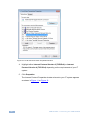
Connecting the Ethernet Port Directly to a PC
You can connect the Ethernet port of the VSM-4x4HFS directly to the Ethernet port
on your PC using a crossover cable with RJ-45 connectors.
i
This type of connection is recommended for identifying the
VSM-4x4HFS with the factory configured default IP address.
After connecting the VSM-4x4HFS to the Ethernet port, configure your PC as
follows:
1. Click Start > Control Panel > Network and Sharing Center.
2. Click Change Adapter Settings.
3. Highlight the network adapter you want to use to connect to the device and
click Change settings of this connection.
The Local Area Connection Properties window for the selected network
adapter appears as shown in Figure 10.
VSM-4x4HFS - Controlling the VSM-4x4HFS
29
Figure 10: Local Area Connection Properties Window
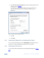
4. Highlight either Internet Protocol Version 6 (TCP/IPv6) or Internet
Protocol Version 4 (TCP/IPv4) depending on the requirements of your IT
system.
5. Click Properties.
The Internet Protocol Properties window relevant to your IT system appears
as shown in Figure 11 or Figure 12.
30
VSM-4x4HFS - Controlling the VSM-4x4HFS
Figure 11: Internet Protocol Version 4 Properties Window
Figure 12: Internet Protocol Version 6 Properties Window
VSM-4x4HFS - Controlling the VSM-4x4HFS
31
6. Select Use the following IP Address for static IP addressing and fill in the
details as shown in Figure 13.
For TCP/IPv4 you can use any IP address in the range 192.168.1.1 to
192.168.1.255 (excluding 192.168.1.39) that is provided by your IT
department.
Figure 13: Internet Protocol Properties Window
7. Click OK.
8. Click Close.
6.4.2
Connecting the Ethernet Port via a Network Hub or Switch
You can connect the Ethernet port of the VSM-4x4HFS to the Ethernet port on a
network hub or using a straight-through cable with RJ-45 connectors.
6.4.3
Configuring the Ethernet Port
You can set the Ethernet parameters via the embedded Web pages (see Section
8.3.2).
32
VSM-4x4HFS - Controlling the VSM-4x4HFS
6.5
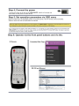
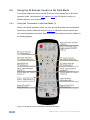
Controlling via the Infrared Remote Control Transmitter
You can control the VSM-4x4HFS from the infrared remote control transmitter:
Keys
Function
POWER
Toggle the power save mode
ON or OFF
IDENTIFY
Identify the inputs on each
output
INFO
Press to indicate on each
output, which input is displayed
on the output
MUTE
Toggle between muting
(blocking out the sound) and
enabling the audio output
MATRIX
Set to Matrix mode (see
Section 5.1)
Set to video wall mode (see
Section 5.2)
Set to dual mode (see Section
5.3)
VID WALL
DUAL
QUAD
STO
Set to quad mode (see Section
5.4)
Store a configuration
RCL
Recall a configuration
Four navigation keys
Figure 14: Infrared Remote Control
Transmitter
VSM-4x4HFS - Controlling the VSM-4x4HFS
OK
Accept changes
MENU
Enter the OSD menu
ESC
EXIT the menu
ALL
Select all the outputs
OFF
Disconnect a selected input
TAKE
Press to carry out a setup
OUT
Select an output (A to D)
IN
Select an input (1 to 4)
AUDIO
Select the audio source (1 to 4)
720p Reset Reset the resolution to 720p
XGA Reset
Reset the resolution to XGA
Panel Lock
Lock/unlock the front panel
buttons
33
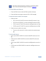
6.6
Using the IR Remote Control in the Dual Mode
This section describes how to use the IR remote control transmitter in the DUAL
operation mode. Sections and 6.6.1 explain 6.6.2 the IR Remote functions in
different ways for your convenience.
6.6.1
Using the Transmitter in the Dual Mode (1)
When in the DUAL operation mode, you can use the IR remote control transmitter
shortcuts to perform additional actions. Figure 15 shows the remote control with
dual mode operation instructions. Note that these instructions are further detailed in
the following pages.
Figure 15: IR Remote Control Transmitter Dual Mode Shortcuts
34
VSM-4x4HFS - Controlling the VSM-4x4HFS
i
Note that the letters that appear in brackets in the following pages,
refer to the same letters that appear in brackets in Figure 15.
To use the DUAL mode Shortcuts:
1. Press the DUAL button to select the DUAL operation button (a).
2. Press the DUAL button again to select the PIP or POP mode (b).
To select the inputs to switch to the outputs:
1. Select an output:
PIP A: press OUT A/OUT B to select the Main/PIP window for A (c)
PIP B: press OUT B/OUT C to select the Main/PIP window for B (d)
POP A: press OUT A/OUT B to select the Left/Right window for A (e)
POP B: press OUT C/OUT D to select the Left/Right window for B (f)
2. Select the input to switch to the output:
Press one of the inputs (IN 1 to IN 4) to switch to the selected output
(g).
To set the audio source:
PIP A: press AUDIO 1/AUDIO 2 to select the Main/PIP audio source for A
(h)
PIP B: press the AUDIO 3/AUDIO 4 to select the Main/PIP audio source
for B (i)
POP A: press AUDIO 1/AUDIO 2 to select the Left/Right audio source for A
(h)
POP B: press the AUDIO 3/AUDIO 4 to select the Left/Right audio source
for B (i)
VSM-4x4HFS - Controlling the VSM-4x4HFS
35
To perform various PIP mode operations:
1. Make sure you are in the PIP mode.
2. Select the PIP output:
Press OUT A to select PIP A (j)
Press OUT B to select PIP B (k)
3. Perform any of the following operations.
6.6.2
Press up/down arrow to select the PIP window size (l)
Press the left/right arrow to select the PIP window position (m)
Press the OK button to swap between main and PIP windows (n)
Using the Transmitter in the Dual Mode (2)
To use the DUAL mode Shortcuts:
To select the inputs to switch to the outputs:
For PIP/POP A:
For PIP/POP B:
36
VSM-4x4HFS - Controlling the VSM-4x4HFS
To set the audio source:
For PIP/POP A:
For PIP/POP B:
To perform various PIP mode operations (make sure you are in the PIP mode):
VSM-4x4HFS - Controlling the VSM-4x4HFS
37
38
VSM-4x4HFS - Controlling the VSM-4x4HFS
7
Firmware Upgrade via USB
You can upgrade the VSM-4x4HFS via the USB connector on the rear panel.
i
The latest firmware version, can be downloaded from the Kramer Web
site at http://www.kramerelectronics.com/support/downloads.asp
To upgrade the firmware:
1. Connect the VSM-4x4HFS USB connector to the PC via a USB cable while
the power supply is disconnected.
2. Connect the power supply and turn the VSM-4x4HFS on.
The PC automatically connects with the VSM-4x4HFS and a file folder
opens on screen (same as would open when using a Memory stick).
3. Copy the VSM-4X4HFS_vx.xx.BIN firmware and copy it onto the newly
opened file folder.
4. Disconnect the USB cable.
5. Power the VSM-4x4HFS off and then on to check if the firmware was
updated.
VSM-4x4HFS - Firmware Upgrade via USB
39
8
Using the Embedded Web Pages
The Web pages let you control the VSM-4x4HFS via the Ethernet. The Web pages
include all the OSD items and more, and are accessed using a Web browser and
an Ethernet connection.
Before attempting to connect:
Perform the procedures in Section 6.4.
Ensure that your browser is supported
The following operating systems and Web browsers are supported:
For Windows 7 and higher:
Chrome version 35
Firefox version 30
Internet Explorer version 10
Safari 7
For Mac (PC):
Chrome version 35
For iOS:
Chrome version 35
For Android OS:
8.1
Chrome version 35
Browsing the VSM-4x4HFS Web Pages
To browse the VSM-4x4HFS Web pages:
1. Open your Internet browser.
2. Type the IP number of the device in the Address bar of your browser. For
example, the default IP number:
The Routing (first) page loads.
40
VSM-4x4HFS - Using the Embedded Web Pages
There are six Web pages:
8.2
The Routing page (see Section 8.2)
The Device settings page (See Section 8.3)
The Output settings page (see Section 8.4)
The HDCP settings page (see Section 8.5)
The EDID management page (see Section 8.6)
The About page (see Section 8.7)
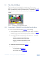
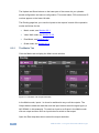
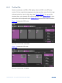
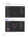
The Routing Page
Figure 16 shows the Routing page that is also the first page that appears following
the loading page. The routing page includes a tab for each of the four operation
modes.
Figure 16: The Routing Page
VSM-4x4HFS - Using the Embedded Web Pages
41
The Upload and Save buttons on the lower part of the screen let you upload a
saved configuration and save a configuration. The model name, FW version and IP
number appear on the lower left side.
The Routing page lets you route the input/s to the outputs in each of the operation
modes as follows for the:
8.2.1
Matrix mode, see Section 8.2.1
Video Wall mode, see Section 8.2.2
Dual Mode, see Section 8.2.3
Quad mode, see Section 8.2.4
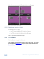
The Matrix Tab
Click the Matrix tab to display the Matrix mode window:
Figure 17: The Matrix Tab output Resolution
In the Matrix mode, inputs 1 to 4 can be switched to any or all the outputs. The
Output buttons show the resolution and the input buttons show the signal type (or
NO SIGNAL in this example). To switch an Input to an Output in the Matrix mode
click an output and then click an input button to switch to that output.
Open the Res drop-down-box to select the output resolution.
42
VSM-4x4HFS - Using the Embedded Web Pages
Figure 18: The Matrix Tab – Set the Output Resolution
8.2.1.1 The Edit Input Window
Click the edit icon
to edit the input button. This window lets you edit the input
label:
Figure 19: The Matrix Tab – the Input Edit Window
Type a label name (for example, DVD Player):
VSM-4x4HFS - Using the Embedded Web Pages
43
Figure 20: The Matrix Tab – Type the new label
Note that you need to Click the save button
to save the new Label. The
following message appears:
Click OK to save the label name.
Toggle the View
/
button to view the label in the Web pages:
Figure 21: The Matrix Tab – View the Label
Click
to exit the input editing window.
8.2.1.2 Storing and Recalling a Configuration
Click the Store button
44
to store a configuration:
VSM-4x4HFS - Using the Embedded Web Pages
Figure 22: The Matrix Tab – Store a Configuration
1. Select one of the four presets.
The configuration is saved.
2. Click the
icon to exit the preset window.
Click the Recall button
to recall a configuration:
Figure 23: The Matrix Tab – Recall a Configuration
1. Select one of the four presets.
The configuration is uploaded.
2. Click the
icon to exit the preset window.
VSM-4x4HFS - Using the Embedded Web Pages
45
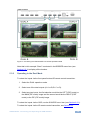
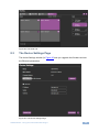
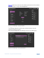
8.2.2
The Video Wall Tab
Click the Video Wall tab to display the Video Wall mode window:
Figure 24: The Video Wall Tab
The video wall tab displays four outputs in a video wall display. Click one of the four
input buttons to switch an input to the video wall. You can edit the input label (see
Section 8.2.1.1), store and recall a video wall configuration (see Section 8.2.1.2)
and set the output resolution.
8.2.2.1 Bezel Correction
Set the horizontal and vertical bezel correction (see Section 5.2) via the video Wall
tab:
Figure 25: The Video Wall Tab – Bezel Correction
46
VSM-4x4HFS - Using the Embedded Web Pages
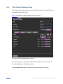
8.2.3
The Dual Tab
Set the mode button to (POP or PIP) display either the POP or the PIP setup
modes. Click an output button (appear as windows) and then one of the four input
buttons to switch an input to that output (see Section 8.2.3.1). You can set the
borders (show, only selected, off), edit the input label (see Section 8.2.1.1), store
and recall a dual configuration (see Section 8.2.1.2) and set the output resolution.
Figure 26 shows the POP mode:
Figure 26: The Dual Tab – POP Mode
Figure 27 shows the PIP mode:
Figure 27: The Dual Tab – PIP Mode
VSM-4x4HFS - Using the Embedded Web Pages
47
In the PIP mode you can set the PIP position for the A and B outputs:
Figure 28: The Dual Tab – PIP Position
8.2.3.1 Switching an Input to an Output
To switch an input to an output:
For PIP: select the MAIN or PIP on the A or B outputs
For POP: select the Left or Right on the A or B outputs
Click an input button to switch to the output.
8.2.4
The Quad Mode
Click the Quad tab to display the Quad mode.
Click one of the four input buttons to switch an input to each output. You can edit
the input label (see Section 8.2.1.1), store and recall a Quad configuration (see
Section 8.2.1.2), set the borders and set the output resolution.
48
VSM-4x4HFS - Using the Embedded Web Pages
Figure 29: The Quad Tab
8.3
The Device Settings Page
The device Settings window (in Figure 30) lets you upgrade the firmware and set
the Ethernet parameters.
Figure 30: The Device Settings Page
VSM-4x4HFS - Using the Embedded Web Pages
49
8.3.1
Upgrade the Firmware
You can upgrade the firmware via the Device Settings page. To do so:
1. Choose the firmware file by clicking the Choose File.
2. Select the firmware file and click open. The file name appears in the Device
Settings Web page.
3. Click the Upgrade button.
4. Click OK. The flash memory is erased and then the file is uploaded.
Following reset, make sure that the updated firmware version appears in the Device
Settings (Firmware version).
8.3.2
Changing the Ethernet Settings
You can change the Ethernet parameters by typing the changing and clicking the
Set changes button. Note that:
When changing the IP number, the change is immediate and the Web page
reloads with the new IP number (see Figure 32).
Figure 31: The Device Settings Page – Ethernet Settings
50
VSM-4x4HFS - Using the Embedded Web Pages
Figure 32: The Device Settings Page – IP Number Settings
To access the information window, click the
icon on the lower right side of the
page.
Figure 33: The Device Settings Page – the Information Window
8.3.3
Factory Reset
Click the Factory reset button to reset the device. Note that you will have to type the
new IP into your URL after reset is complete (about 10 seconds).
Figure 34: The Device Settings Page – Factory Reset
VSM-4x4HFS - Using the Embedded Web Pages
51
8.4
The Output Settings Page
The Output settings page lets you set the Mode, Resolution, Aspect Ratio and
enable/disable Auto-Sync Off.
Figure 35 shows the Output Settings page for output 1.
Figure 35: The Output Settings Page – Output 1
For each output you can set the output label, the HDCP state, as well as the
Contrast, Brightness, Saturation and Hue.
Click the Reset All buttons to reset the output settings for all outputs.
52
VSM-4x4HFS - Using the Embedded Web Pages
8.5
The HDCP Settings Page
The HDCP settings page summarizes the HDCP data for the inputs and outputs
and lets you change them.
Figure 36: The HDCP Settings Page
VSM-4x4HFS - Using the Embedded Web Pages
53
8.6
The EDID Page
The EDID page lets you copy a selected resolution or the default resolution to one
or more selected inputs.
Figure 37: The EDID Page
Figure 38 shows how to select a resolution from the list and select one or more
inputs. To copy, click the Copy button:
Figure 38: The EDID Page – Copying the Native Timing
54
VSM-4x4HFS - Using the Embedded Web Pages
Figure 38 shows how to select one of the default resolutions from the list and select
one or more inputs. To copy, click the Copy button:
Figure 39: The EDID Page – Copying the Default
The EDID page displays the machine name, selected resolution, the audio
channels and deep color support.
After clicking the Copy button, the EDID page shows the copy EDID results:
Figure 40: The EDID Page –The Copy EDID Results
VSM-4x4HFS - Using the Embedded Web Pages
55
8.7
The About Page
The VSM-4x4HFS About page lets you view the Web page version and Kramer
Electronics Ltd details.
Figure 41: The About Page
8.8
Save or Upload a Configuration
The VSM-4x4HFS Web page lets you upload a saved configuration or save a
configuration. To do so, click the Upload and buttons which are located at the lower
part of the menu list, respectively.
When saving a configuration, the file automatically saves it to the Downloads.
When loading a configuration the following message appears:
Figure 42: Loading a Configuration
56
VSM-4x4HFS - Using the Embedded Web Pages
9
Technical Specifications
INPUTS:
4 HDMI connectors (HDMI, HDCP version 1.1)
OUTPUTS:
4 HDMI connectors (HDMI, HDCP version 1.1)
OUTPUT RESOLUTIONS:
NATIVE , 480p, 576p, 720p50, 720p60, 1080p24,
1080p50, 1080p60, 1024x768, 1280x800, 1280x1024,
1366x768, 1440x900, 1600x900, 1600x1200, 1680x1050
or 1920x1200
POWER SOURCE:
100-240V AC, 27VA max.
OPERATING TEMPERATURE:
0° to +40°C (32° to 104°F)
STORAGE TEMPERATURE:
-40° to +70°C (-40° to 158°F)
HUMIDITY:
10% to 90%, RHL non-condensing
DIMENSIONS:
19" x 7" x 1U (W, D, H) rack mountable
WEIGHT:
2.7kg (6lbs) approx.
INCLUDED ACCESSORIES:
Power cord, rack ears, IR remote control
Specifications are subject to change without notice at http://www.kramerelectronics.com
9.1
Default Communication Parameters
RS-232
Baud Rate:
115,200
Data Bits:
8
Stop Bits:
1
Parity:
None
Command Format:
ASCII
Example (Route the video from the HDMI2 input to the HDMI1
output port in the Matrix mode):
#ROUTE 0,1,2<cr>
Ethernet
To reset the IP settings to the factory reset values go to : Menu-> Factory-> RESET->Change
the option to YES and press Enter
IP Address:
192.168.1.39
Subnet mask:
255.255.255.0
Default gateway:
192.168.1.254
TCP Port #:
Not supported
Default UDP Port #:
50000
Maximum UDP Ports:
4
Full Factory Reset
OSD
Go to : Menu-> FACTORY DEFAULT -> Change the option to YES
and press Enter
P3000
Use “FACTORY” command
Front panel buttons
Press the MENU Button while plugging the power to reset the
machine
VSM-4x4HFS - Technical Specifications
57
9.2
9.3
58
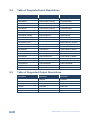
Table of Supported Input Resolutions
Resolution
Resolution
Resolution
No signal
1152x864p75
1400x1050p60
640x480p59
1280x720p25 (720p25)
1440x900p60RB
640x480p72
1280x720p29 (720p29)
1440x900p60
640x480p75
1280x720p30 (720p30)
1440x900p75
640x480p85
1280x720p50 (720p50)
1600x900p60RB
720x400p70
1280x720p59 (720p59)
1600x1200p60
720x480i59 (480i59)
1280x720p60 (720p60)
1680x1050p60RB
720x480i60 (480i60)
1280x720p60CVT
1680x1050p60
720x480p59 (480p59)
1280x768p60RB
1920x1080p23 (1080p23)
720x480p60 (480p60)
1280x768p60
1920x1080p24 (1080p24)
720x576i50 (576i)
1280x768p75
1920x1080p25 (1080p25)
720x576p50 (576p)
1280x800p60RB
1920x1080p29 (1080p29)
800x600p56
1280x800p60
1920x1080p30 (1080p30)
800x600p60
1280x800p75
1920x1080i50 (1080i50)
800x600p72
1280x960p60
1920x1080p50 (1080p50)
800x600p75
1280x1024p60
1920x1080i59 (1080i59)
800x600p85
1280x1024p60CVT
1920x1080i60 (1080i60)
1024x768p60
1280x1024p75
1920x1080p59 (1080p59)
1024x768p70
1360x768p60
1920x1080p60 (1080p60)
1024x768p75
1366x768p60RB
1920x1200p60RB
1024x768p85
1366x768p60
1152x864p70
1400x1050p60RB
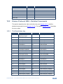
Table of Supported Output Resolutions
Resolution
Resolution
Resolution
Native
1080p50
1440x900
480p
1080p60
1600x900
576p
1024x768
1600x1200
720p50
1280x800
1680x1050
720p60
1280x1024
1920x1200
1080p24
1366x768
VSM-4x4HFS - Technical Specifications
10
The VSM-4x4HFS RS-232 Communication
Protocol
The VSM-4x4HFS can be operated using serial commands from a PC, remote
controller, or touch screen. The unit communicates using the default Kramer
Protocol 3000.
10.1
10.1.1
Protocol 3000
Kramer Protocol 3000 syntax (see section 10.1.1)
Kramer Protocol 3000 commands (see section 10.1.2)
Kramer Protocol 3000 Syntax
Protocol 3000 communicates at a data rate of 115200 baud, no parity, 8 data bits
and 1 stop bit.
10.1.1.1 Host Message Format
Start
Address (optional)
Body
Delimiter
#
Destination_id@
Message
CR
Simple Command
Command string with only one command without addressing:
Start
Body
Delimiter
#
Command SP Parameter_1,Parameter_2,…
CR
Command String
Formal syntax with commands concatenation and addressing:
Start
Address
Body
#
Destination_id@
Command_1 Parameter1_1,Parameter1_2,…|
CR
Command_2 Parameter2_1,Parameter2_2,…|
Command_3 Parameter3_1,Parameter3_2,…|…
VSM-4x4HFS - The VSM-4x4HFS RS-232 Communication Protocol
Delimiter
59
10.1.1.2 Device Message Format
Start
Address (optional) Body
~
Sender_id@
Message
delimiter
CR LF
Device Long Response
Echoing command:
Start
Address (optional) Body
~
Sender_id@
Command SP [Param1 ,Param2 …] result
Delimiter
CR LF
CR = Carriage return (ASCII 13 = 0x0D)
LF = Line feed (ASCII 10 = 0x0A)
SP = Space (ASCII 32 = 0x20)
10.1.1.3 Command Terms
Command
A sequence of ASCII letters ('A'-'Z', 'a'-'z' and '-').
Command and parameters must be separated by at least one space.
Parameters
A sequence of alphameric ASCII characters ('0'-'9','A'-'Z','a'-'z' and some special
characters for specific commands). Parameters are separated by commas.
Message string
Every command entered as part of a message string begins with a message
starting character and ends with a message closing character.
Note: A string can contain more than one command. Commands are separated by
a pipe ( '|' ) character.
Message starting character
'#' – For host command/query
'~' – For machine response
Device address (Optional, for K-NET)
K-NET Device ID followed by '@'
60
VSM-4x4HFS - The VSM-4x4HFS RS-232 Communication Protocol
Query sign
'?' follows some commands to define a query request.
Message closing character
CR – For host messages; carriage return (ASCII 13)
CRLF – For machine messages; carriage return (ASCII 13) + line-feed (ASCII 10)
Command chain separator character
When a message string contains more than one command, a pipe ( '|' ) character
separates each command.
Spaces between parameters or command terms are ignored.
10.1.1.4 Entering Commands
You can directly enter all commands using a terminal with ASCII communications
software, such as HyperTerminal, Hercules, etc. Connect the terminal to the serial
or Ethernet port on the Kramer device. To enter CR press the Enter key.
( LF is also sent but is ignored by command parser).
For commands sent from some non-Kramer controllers like Crestron, some
characters require special coding (such as, /X##). Refer to the controller manual.
10.1.1.5 Command Forms
Some commands have short name syntax in addition to long name syntax to allow
faster typing. The response is always in long syntax.
10.1.1.6 Command Chaining
Multiple commands can be chained in the same string. Each command is delimited
by a pipe character ( '|' ). When chaining commands, enter the message starting
character and the message closing character only once, at the beginning of the
string and at the end.
Commands in the string do not execute until the closing character is entered.
A separate response is sent for every command in the chain.
10.1.1.7 Maximum String Length
64 characters
VSM-4x4HFS - The VSM-4x4HFS RS-232 Communication Protocol
61
10.1.2
Kramer Protocol 3000 Commands
Command
Short Form
Description
#
Protocol handshaking
#BUILD-DATE?
Read device build date
#FACTORY
Reset to factory default configuration
#HELP
List of commands
#MODEL?
Read device model
#PROT-VER?
Read device protocol version
#RESET
SN?
#VERSION?
Read device firmware version
#DISPLAY?
Get output HPD status
#HDCP-MOD
#HDCP-MOD?
#HDCP-STAT?
#INFO-IO?
#INFO-PRST?
#LOCK-FP
LCK
Lock front panel
#LOCK-FP?
LCK?
GET Lock front panel
#PRST-LST?
#PRST-RCL
#PRST-STO
#PRST-VID?
#PRST-VID?
#SIGNAL?
#ROUTE
#ROUTE?
#VID-RES
Set input/output resolution
#VID-RES?
Get input/output resolution
#VMUTE
#VMUTE?
#NET-DHCP
NTDH
Set DHCP mode
#NET-DHCP?
NTDH?
Get DHCP mode
#NET-GATE
NTGT
Set Gateway IP
#NET-GATE?
NTGT?
Get Gateway IP
#NET-IP
NTIP
Set device IP address
#NET-IP?
NTIP?
Get device IP address
#NET-MAC?
NTMC?
Get MAC address
#NET-MASK
NTMSK
Set device subnet mask
#NET-MASK?
NTMSK?
Get device subnet mask
#BRIGHTNESS
#CONTRAST
#CONTRAST?
#IMAGE-PROP
62
VSM-4x4HFS - The VSM-4x4HFS RS-232 Communication Protocol
Command
Short Form
Description
#IMAGE-PROP?
#SCLR-AS
#SCLR-AS
#SHOW-OSD
#SHOW-OSD?
#FCT-MAC
#FCT-SN
10.2
Kramer Protocol 3000 – Detailed Commands
This section describes the video resolutions key (see Section 10.2.1) and the
detailed commands list (see Section 10.2.2). The table in Section 10.2.3 describes
the error codes.
10.2.1
The Resolutions key
#
Resolution
#
Resolution
0
No signal (for input)
Native (for output
32
1280x768p75
1
640x480p59
33
1280x800p60RB
2
640x480p72
34
1280x800p60
3
640x480p75
35
1280x800p75
4
640x480p85
36
1280x960p60
5
720x400p70
37
1280x1024p60
6
720x480i59 (480i59)
38
1280x1024p60CVT
7
720x480i60 (480i60)
39
1280x1024p75
8
720x480p59 (480p59)
40
1360x768p60
9
720x480p60 (480p60)
41
1366x768p60RB
10
720x576i50 (576i)
42
1366x768p60
11
720x576p50 (576p)
43
1400x1050p60RB
12
800x600p56
44
1400x1050p60
13
800x600p60
45
1440x900p60RB
14
800x600p72
46
1440x900p60
15
800x600p75
47
1440x900p75
16
800x600p85
48
1600x900p60RB
17
1024x768p60
49
1600x1200p60
18
1024x768p70
50
1680x1050p60RB
19
1024x768p75
51
1680x1050p60
20
1024x768p85
52
1920x1080p23 (1080p23)
21
1152x864p70
53
1920x1080p24 (1080p24)
22
1152x864p75
54
1920x1080p25 (1080p25)
23
1280x720p25 (720p25)
55
1920x1080p29 (1080p29)
VSM-4x4HFS - The VSM-4x4HFS RS-232 Communication Protocol
63
10.2.2
#
Resolution
#
Resolution
24
1280x720p29 (720p29)
56
1920x1080p30 (1080p30)
25
1280x720p30 (720p30)
57
1920x1080i50 (1080i50)
26
1280x720p50 (720p50)
58
1920x1080p50 (1080p50)
27
1280x720p59 (720p59)
59
1920x1080i59 (1080i59)
28
1280x720p60 (720p60)
60
1920x1080i60 (1080i60)
29
1280x720p60CVT
61
1920x1080p59 (1080p59)
30
1280x768p60RB
62
1920x1080p60 (1080p60)
31
1280x768p60
63
1920x1200p60RB
The Commands
Command – BUILD-DATE
Command Type – System-mandatory
Command Name
Permission
Transparency
Set:
BUILD-DATE
End User
-
Get:
-
-
-
Description
Syntax
Set:
Read device build date
#BUILD-DATE?␍
Get :
-
-
Response
~nn@BUILD-DATE␠date␠time␍␊
Parameters
date – Format: YYYY/MM/DD where YYYY = Year, MM = Month, DD = Day
time – Format: hh:mm:ss where hh = hours, mm = minutes, ss = seconds
Command - FACTORY
Command Type - System-mandatory
Command Name
Permission
Transparency
Set:
FACTORY
End User
Public
Get:
-
-
-
Description
Syntax
Set:
Reset device to factory default
configuration
#FACTORY␍
Get:
-
-
Response
~nn@FACTORY␠OK␍␊
Notes
This command deletes all user data from the device. The deletion can take some time.
64
VSM-4x4HFS - The VSM-4x4HFS RS-232 Communication Protocol
Command – HELP
Command Type – System-mandatory
Command Name
Permission
Transparency
Set:
-
-
-
Get:
HELP
End User
-
Description
Syntax
Set:
-
-
Get :
Get command list
2 options:
1. #HELP␍
Response
1. Multi-line: ~nn@Device available protocol 3000 commands:␍␊command,␠command…␍␊
Command – MODEL?
Command Type – System-mandatory
Command Name
Permission
Transparency
Set:
-
-
-
Get:
MODEL?
End User
-
Description
Syntax
Set:
-
-
Get :
Get device model
#MODEL?␍
Response
~nn@MODEL␠VSM-4x4HFS␍␊
Parameters
model_name – String of up to 19 printable ASCII chars
Command – PROT-VER?
Command Type – System-mandatory
Permission
Transparency
Set:
Command Name
-
-
-
Get:
PROT-VER?
End User
-
Description
Syntax
Set:
-
-
Get :
Get protocol version
#PROT-VER?␍
Response
~nn@PROT-VER␠3000:version␍␊
Parameters
Version – Format: XX.XX where X is a decimal digit
VSM-4x4HFS - The VSM-4x4HFS RS-232 Communication Protocol
65
Command –RESET
Command Type – System-mandatory
Command Name
Permission
Transparency
Set:
RESET
Administrator
-
Get:
-
-
-
Description
Syntax
Set:
Reset device
#RESET␍
Get :
-
-
Response
~nn@RESET␠OK␍␊
Notes
To avoid locking the port due to a USB bug in Windows, disconnect USB connections immediately
after running this command. If the port was locked, disconnect and reconnect the cable to reopen the
port.
Command - SN?
Command Type - System-mandatory
Permission
Transparency
Set:
Command Name
-
-
-
Get:
SN?
End User
Public
Description
Syntax
Set:
-
-
Get:
Get device serial number
#SN?␍
Response
~nn@SN␠serial_number␍␊
Parameters
serial_number - 11 decimal digits, factory assigned
Notes
For new products with 14 digit serial numbers, use only the last 11 digits
Command –VERSION?
Command Type – System-mandatory
Command Name
Permission
Transparency
Set:
-
-
-
Get:
VERSION?
End User
-
Description
Syntax
Set:
-
-
Get :
Get version number
#VERSION?␍
Response
~nn@VERSION␠firmware_version␍␊
Parameters
firmware_version – Format: XX.XX.XXXX where the digits group are: major.minor.build version
66
VSM-4x4HFS - The VSM-4x4HFS RS-232 Communication Protocol
Command – DISPLAY?
Command Type - System
Command Name
Permission
Transparency
Set :
-
-
-
Get
DISPLAY?
End User
Public
Description
Syntax
Set:
-
-
Get:
Get output status of connected display
#DISPLAY? ␠P1 ␍
Response
~ nn@DISPLAY ␠ P1,P2 ␍␊
Parameters
P1 (Output _id) – 1=OUT A; 2=OUT B; 3=OUT C; 4=OUT D; *=ALL
P2 (status) – 0=sink is not valid; 1=sink is valid; 2=sink & good EDID are valid
Response triggers
After execution, response is sent to the com port from which the Get was received
Response is sent after every change in output HPD status ON to OFF
Response is sent after every change in output HPD status OFF to ON and ALL parameters (new
EDID, etc.) are stable and valid
Command – HDCP-MOD
Command Name
Command Type – System
Permission
Transparency
Set:
HDCP-MOD
Administrator
Public
Get:
HDCP-MOD?
End User
Public
Description
Syntax
Set:
Set Input/Output HDCP mode
#HDCP-MOD ␠ P1,P2,P3 ␍
Get :
Get Input/Output HDCP mode
#HDCP-MOD? ␠ P1,P2 ␍
Response
Set / Get : ~ nn @HDCP-MOD ␠ P1,P2,P3 ␍␊
Parameters
P1 (Stage) – 0=Input; 1=Output
P2 (Stage_id) – (stage0) – 1=IN1; 2=IN2; 3=IN3; 4=IN4; (stage1) – 1=OUT A; 2=OUT B; 3=OUT C;
4=OUT B; *=ALL
P3 (Mode) – (stage0) – 0=Off; 1=On; (stage1) – 2=Follow In, 3=Follow Out
Response triggers
Response is sent to the com port from which the Set (before execution) / Get command was
received
Response is sent to all com ports after execution if HDCP-MOD was set any other external
control device (button press, device menu and similar) or genlock status changed
Notes
Set HDCP working mode on device input :
HDCP supported
– HDCP_ON [default]
HDCP not supported – HDCP OFF
HDCP support changes following detected sink – MIRROR OUTPUT
VSM-4x4HFS - The VSM-4x4HFS RS-232 Communication Protocol
67
Command - HDCP-STAT
Command Type - System
Command Name
Permission
Transparency
Set:
-
-
-
Get:
HDCP-STAT?
End User
Public
Description
Syntax
Set:
None
-
Get:
Get HDCP signal status
#HDCP-STAT?␠stage,stage_id,Mode␍
Response
Set / Get: ~ nn@HDCP-STAT␠stage,stage_id,mode␍␊
Parameters
P1 (Stage) – 0=Input; 1=Output
P2 (Stage_id) – (stage0) – 1=IN1; 2=IN2; 3=IN3; 4=IN4; (stage1) – 1=OUT A; 2=OUT B; 3=OUT C;
4=OUT B; *=ALL
P3 (Mode) – 0=Off; 1=On
Response Triggers
Response is sent to the com port from which the Set (before execution) / Get command was received
Response is sent to all com ports after execution if HDCP-STAT was set by any other external control
device (button press, device menu and similar) or genlock status changed
Command - INFO-IO?
Command Name
Command Type - System
Permission
Transparency
Set:
-
-
-
Get:
INFO-IO?
End User
Public
Description
Syntax
Set:
-
-
Get:
Get in/out count
#INFO-IO?␍
Response
~nn@INFO-IO?␠IN␠ inputs_count, OUT␠outputs_count␍␊
Parameters
IN inputs_count = 4
OUT outputs_count = 4
68
VSM-4x4HFS - The VSM-4x4HFS RS-232 Communication Protocol
Command - INFO-PRST?
Command Type - System
Command Name
Permission
Transparency
Set:
-
-
-
Get:
INFO-PRST?
End User
Public
Description
Syntax
Set:
-
-
Get:
Get maximum preset count
#INFO-PRST?␍
Response
~nn@INFO-PRST?␠VID␠preset_video_count, AUD␠preset_audio_count␍␊
Parameters
preset_video_count = 4
preset_audio_count = 0 (does not support audio preset)
Command – LOCK-FP
Command Type – System
Command Name
Permission
Transparency
Set:
LOCK-FP
End User
-
Get:
LOCK-FP?
End User
-
Description
Syntax
Set:
Lock front panel
#LOCK-FP␠P1␍
Get :
Get front panel lock state
#LOCK-FP?␍
Response
nn@LOCK-FP␠P1␠OK␍␊
Parameters
P1 (lock_mode)– 0=Off (unlock); 1=On (lock)
Command - PRST-LST?
Command Name
Command Type - System
Permission
Transparency
Set:
-
-
-
Get:
PRST-LST?
End User
Public
Description
Syntax
Set:
-
-
Get:
Get saved preset list
#PRST-LST?␍
Response
~nn@PRST-LST␠ preset, preset, … ␍␊
Parameters
Preset = 1,2,3,4
VSM-4x4HFS - The VSM-4x4HFS RS-232 Communication Protocol
69
Command - PRST-RCL
Command Type - System
Command Name
Permission
Transparency
Set:
PRST-RCL
End User
Public
Get:
-
-
-
Description
Syntax
Set:
Recall saved preset list
#PRST-RCL␠ preset ␍
Get:
-
-
Response
~nn@PRST-RCL␠preset␍␊
Parameters
preset – 1,2,3 or 4
Notes
In most units, video and audio presets with the same number are stored and recalled together by
commands #PRST-STO and #PRST-RCL
Command - PRST-STO
Command Type - System
Command Name
Permission
Transparency
Set:
PRST-STO
End User
Public
Get:
-
-
-
Description
Syntax
Set:
Store current connections,
volumes and modes in preset
#PRST-STO␠preset ␍
Get:
-
-
Response
~nn@PRST-STO␠ preset␍␊
Parameters
preset – 1,2,3 or 4
Notes
In most units, video and audio presets with the same number are stored and recalled together by
commands #PRST-STO and #PRST-RCL
70
VSM-4x4HFS - The VSM-4x4HFS RS-232 Communication Protocol
Command - PRST-VID?
Command Type - System
Command Name
Permission
Transparency
Set:
-
-
-
Get:
PRST-VID?
End User
Public
Description
Syntax
Set:
-
-
Get:
Get video connections from saved preset
#PRST-VID?␠preset, out␍
#PRST-VID?␠preset, * ␍
Response
~nn@PRST-VID␠preset, in>out ␍␊
~nn@PRST-VID␠preset, in>1, in>2, in>3, … ␍␊
Parameters
preset – 1,2,3 or 4
in – 1=IN1; 2=IN2; 3=IN3; 4=IN4; 5=OFF
> - connection character between in and out parameters
out – 1=OUT A; 2=OUT B; 3=OUT C; 4=OUT D; '*' for all outputs
Notes
In most units, video and audio presets with the same number are stored and recalled together by
commands #PRST-STO and #PRST-RCL
Examples
Store current audio and video connections,
volumes and modes to preset 4
#PRST-STO 4␍
~PRST-STO 4␍␊
Recall audio and video connections from
preset 3
# PRST-RCL 3␍
~PRST-RCL 3␍␊
Show source of video output 2 from preset 3
#PRST-VID? 3,2␍
~PRST-VID 3, 4>2␍␊
Command – SIGNAL
Command Type - System
Command Name
Permission
Transparency
Set :
-
-
-
Get
SIGNAL?
End User
Public
Description
Syntax
Set:
-
-
Get:
Get input signal lock status
#SIGNAL? ␠P1 ␍
Response
~ nn@SIGNAL ␠ inp_id, status ␍␊
Parameters
Inp_id (Input number)– 1=IN1; 2=IN2; 3=IN3; 4=IN4; *=ALL
status – 0=signal is not valid; 1=signal is valid
Response triggers
After execution, response is sent to the com port from which the Get was received
Response is sent after every change in input signal status ON to OFF, or OFF to ON
VSM-4x4HFS - The VSM-4x4HFS RS-232 Communication Protocol
71
Command – ROUTE
Command Type –
Command Name
Permission
Transparency
Set:
ROUTE
End User
-
Get:
ROUTE?
End User
-
Description
Syntax
Set:
Set layer routing
# ROUTE ␠ P1,P2,P3 ␍
Get :
Get layer routing
# ROUTE? ␠ P1,P2 ␍
Response
~ nn@ ROUTE ␠ P1,P2,P3 ␍␊
Parameters
P1 (layer) – 0=Video; 1=Audio (for DUAL and QUAD modes only);
P2 (dest) – 1=OUT A; 2=OUT B; 3=OUT C; 4=OUT D; *= ALL
P3 (src) – 1=IN1; 2=IN2; 3=IN3; 4=IN4; 5=OFF (not for audio)
DUAL mode audio;
P2 (dest) – 1=OUT A; 2=OUT B; 3=OUT C; 4=OUT D
P3 (src) – for DUAL A: 1=IN1; 2=IN2; for DUAL B: 3=IN3; 4=IN4
Notes
This command replaces all other routing commands.
Command – VID-RES
Command Type - Video
Command Name
Permission
Transparency
Set :
VID-RES
End User
Public
Get
VID-RES?
End User
Public
Description
Syntax
Set:
Set video resolution
#VID-RES ␠P1,P2,P3,P4 ␍
Get:
Get video resolution
#VID-RES? ␠ P1,P2,P3 ␍
Response
~ nn@VID-RES ␠ P1,P2,P3,P4 ␍␊
Parameters
P1 (stage) – 0=Input; 1=Output
Note that under SET, stage=1 only
P2 (stage_id) – stage0: 1=IN1; 2=IN2; 3=IN3; 4=IN4; stage1: 1=OUT A; 2=OUT B; 3=OUT C; 4=OUT
D; *=ALL
P3 (is_native) – 0=Off; 1=On
P4 (video resolutions) see Section 10.2.1
Response triggers
After execution, response is sent to the com port from which the Set /Get was received
After execution, response is sent to all com ports if VID-RES was set by any other external control
device (button press, device menu and similar)
72
VSM-4x4HFS - The VSM-4x4HFS RS-232 Communication Protocol
Notes
1.
2.
3.
“Set” command is only applicable for stage=Output
“Set” command with is_native=ON sets native resolution on selected output (resolution index sent =
0). Device sends as answer actual VIC ID of native resolution
“Get” command with is_native=ON returns native resolution VIC, with is_native=OFF returns current
resolution
Command – VMUTE
Command Name
Command Type – Video
Permission
Transparency
Set:
VMUTE
End User
-
Get:
VMUTE?
End User
-
Description
Syntax
Set:
Set enable/ disable video
on output
# VMUTE ␠ P1,P2 ␍
Get :
Get video on output status
# VMUTE? ␠ P1 ␍
Response
Set / Get : ~ nn@ VMUTE ␠ P1, P2 ␠OK␍␊
Parameters
P1 (output_id) – 1=OUT A; 2=OUT B; 3=OUT C; 4=OUT D; *=ALL
P2 (flag) – 0=disable (free-run); 1=enable
Command – NET-DHCP
Command Name
Command Type – Communication
Permission
Transparency
Set:
NET-DHCP
Administrator
-
Get:
NET-DHCP?
End User
-
Description
Syntax
Set:
Set DHCP mode
#NET-DHCP␠ P1 ␍
Get :
Get DHCP mode
#NET-DHCP?␍
Response
Set: ~nn@ NET-DHCP ␠ P1 ␠OK␍␊
Get: ~nn@ NET-DHCP ␠ mode ␍␊
Parameters
P1 (mode)
0 – Do not use DHCP. Use the IP set by the factory or using the IP set command.
1 – Try to use DHCP. If unavailable, use IP as above.
Notes
Connecting Ethernet to devices with DHCP may take more time in some networks.
To connect with a randomly assigned IP by DHCP, specify the device DNS name (if available) using
the command “NAME”. You can also get an assigned IP by direct connection to USB or RS-232
protocol port if available.
For proper settings consult your network administrator.
VSM-4x4HFS - The VSM-4x4HFS RS-232 Communication Protocol
73
Command – NET-GATE
Command Type – Communication
Command Name
Permission
Transparency
Administrator
-
NET-GATE?
Get:
Description
End User
Syntax
-
Set:
Set Gateway IP
#NET-GATE␠ P1 ␍
Get :
Get Gateway IP
#NET-GATE?␍
Set:
NET-GATE
Response
Set: ~nn@ NET-GATE ␠ P1 ␠OK␍␊
Get: ~nn@ NET-GATE ␠ ip_address ␍␊
Parameters
P1 (valid IP address)=xxx.xxx.xxx.xxx
Notes
A network gateway connects the device via another network and maybe over the Internet. Be careful
of security problems. For proper settings consult your network administrator
Command – NET-IP
Command Type – Communication
Command Name
Permission
Transparency
Set:
NET-IP
Administrator
-
Get:
NET-IP?
End User
-
Description
Syntax
Set:
Set device IP address
#NET-IP␠ P1 ␍
Get :
Get device IP address
#NET-IP?␍
Response
Set: ~nn@ NET-IP ␠ ip_address ␠OK␍␊
Get: ~nn@ NET-IP ␠ ip_address ␍␊
Parameters
P1 (valid IP address)= xxx.xxx.xxx.xxx
Notes
For proper settings consult your network administrator.
Command – NET-MAC?
Command Name
Set:
Get:
Command Type – Communication
Permission
Transparency
NET-MAC?
End User
Description
-
Syntax
Set:
Get :
Get MAC address
#NET-MAC?␍
Response
~nn@NET-MAC␠mac_address␍␊
Parameters
mac_address – Unique MAC address. Format: XX-XX-XX-XX-XX-XX where X is hex digit.
74
VSM-4x4HFS - The VSM-4x4HFS RS-232 Communication Protocol
Command – NET-MASK
Command Type – Communication
Command Name
Permission
Transparency
Set:
NET-MASK
Administrator
-
Get:
NET-MASK?
End User
-
Description
Syntax
Set:
Set device subnet mask
#NET-MASK␠ net_mask ␍
Get :
Get device subnet mask
#NET-MASK? ␍
Response
Set: ~nn@NET-MASK ␠ P1 ␠OK␍␊
Get: ~nn@NET-MASK ␠ net_mask ␍␊
Parameters
P1 (valid IP address)=xxx.xxx.xxx.xxx
Response triggers
The subnet mask limits the Ethernet connection within the local network.
For proper settings consult your network administrator.
Command - BRIGHTNESS
Command Name
Command Type - Multiviewer
Permission
Transparency
Set:
BRIGHTNESS
End User
Public
Get
BRIGHTNESS?
End User
Public
Description
Syntax
Set:
Set window brightness
#BRIGHTNESS␠win_num,value␍
Get:
Get window brightness
#BRIGHTNESS?␠win_num ␍
Response
~ nn@BRIGHTNESS␠win_num, value␍␊
Parameters
win_num – 1=OUT A, 2=OUT B, 3=OUT C, 4=OUT D *=ALL
value – 0~100
Response Triggers
After execution, response is sent to the com port from which the Set/Get was received
After execution, response is sent to all com ports if BRIGHTNESS was set by any other external control
device (button press, device menu and similar)
Notes
Value limits can vary for different devices
Value is a property of input connected to current window. Changing window input source might cause
changes in this value (refer device definitions)
VSM-4x4HFS - The VSM-4x4HFS RS-232 Communication Protocol
75
Command - CONTRAST
Command Type - Multiviewer
Command Name
Permission
Transparency
Set:
CONTRAST
End User
Public
Get
CONTRAST?
End User
Public
Description
Syntax
Set:
Set window contract
#CONTRAST␠win_num, value␍
Get:
Get window contract
#CONTRAST?␠win_num ␍
Response
~ nn@CONTRAST␠win_num, value␍␊
Parameters
win_num – 1=OUT A, 2=OUT B, 3=OUT C, 4=OUT D *=ALL
value – 0~100
Response Triggers
After execution, response is sent to the com port from which the Set/Get was received
After execution, response is sent to all com ports if CONTRAST was set by any other external control
device (button press, device menu and similar)
Notes
Value limits can vary for different devices
Value is a property of input connected to current window. Changing the window input source might
cause changes in this value (refer to device definitions)
Command – IMAGE-PROP
Command Type – Multiviewer/Scaler
Command Name
Permission
Transparency
Set:
IMAGE-PROP
End User
Public
Get:
IMAGE-PROP?
End User
Public
Description
Syntax
Set:
Set the image size (aspect ratio)
# IMAGE-PROP ␠ P1,P2␍
Get :
Get the image size (aspect ratio)
# IMAGE-PROP? ␠ P1␍
Response
Set / Get : ~ nn @IMAGE-PROP ␠ P1,P2 ␠OK␍␊
Parameters
P1 – 1=OUT A, 2=OUT B, 3=OUT C, 4=OUT D *=ALL
Note: all 4 scalers have the same aspect ratio
P2 – 1=Full; 2=Best Fit; 3=Panscan (4:3); 4=letterbox (16:9)
Response triggers
Response is sent to the com port from which the Set (before execution) / Get command was received
After execution, response is sent to all com ports if CMD-NAME was set any other external control
device (button press, device menu and similar) or genlock status was changed
Notes
Sets the image properties of the selected scaler
76
VSM-4x4HFS - The VSM-4x4HFS RS-232 Communication Protocol
Command – SCLR-AS
Command Name
Command Type – Multiviewer/Scaler
Permission
Transparency
Set:
SCLR-AS
End User
Public
Get:
SCLR-AS?
End User
Public
Description
Syntax
Set:
Set auto-sync features (auto sync-off)
# SCLR-AS ␠ P1,P2 ␍
Get :
Get auto-sync features (auto sync-off)
# SCLR-AS?␠ P1 ␍
Response
Set / Get : ~ nn @ SCLR-AS ␠ P1,P2␠OK␍␊
Parameters
P1 –1=OUT A, 2=OUT B, 3=OUT C, 4=OUT D *=ALL
Note that all 4 scalers have the same auto sync-off status
P2 – On/Off – 0=Off; 1=On
Response triggers
Response is sent to the com port from which the Set (before execution) / Get command was received
After execution, response is sent to all com ports if CMD-NAME was set any other external control
device (button press, device menu and similar) or genlock status was changed
Notes
Sets the auto sync features for the selected scaler
Command – SHOW-OSD
Command Name
Command Type – Multiviewer/Scaler
Permission
Transparency
Set:
SHOW-OSD
End User
Public
Get:
SHOW-OSD?
End User
Public
Description
Syntax
Set:
Set the OSD display (INFO menu item in OSD)
# SHOW-OSD ␠ P1␍
Get :
Get the OSD display (INFO menu item in OSD)
# SHOW-OSD?␠ ␍
Response
Set / Get : ~ nn @SHOW-OSD ␠ P1,P2␠OK␍␊
Parameters
P1 –1=OUT A, 2=OUT B, 3=OUT C, 4=OUT D *=ALL
Note that all 4 scalers have the same OSD display
P2 – On/Off – 0=Off; 1=On
Response Triggers
Response is sent to the com port from which the Set (before execution) / Get command was received
After execution, response is sent to all com ports if CMD-NAME was set any other external control
device (button press, device menu and similar) or genlock status was changed
Notes
Displays the OSD of the selected Scaler
VSM-4x4HFS - The VSM-4x4HFS RS-232 Communication Protocol
77
Command - FCT-MAC
Command Type - Ethernet (Secret)
Command Name
Permission
Transparency
Set:
FCT-MAC
Factory
Internal
Get:
-
-
-
Description
Syntax
Set:
Set MAC address
#FCT-MAC␠mac_address␍
Get:
-
-
Response
~nn@FCT-MAC␠mac_address␠OK␍␊
Parameters
mac_address - Unique MAC address. Format: XX-XX-XX-XX-XX-XX where X is a hex digit
Command - FCT-SN
Command Type - System-mandatory (Secret)
Command Name
Permission
Transparency
Set:
FCT-SN
Factory
Internal
Get:
-
-
-
Description
Syntax
Set:
Set serial number
#FCT-SN␠serial_number␍
Get:
-
-
Response
~nn@FCT-SN␠serial_number␠OK␍␊
Parameters
serial_number - 11 decimal digits
Notes
For new products with 14 digit serial numbers, use only the last 11 digits
10.2.3
Error Codes
Error
Description
1
No error
2
Protocol syntax error, 1st char isn’t '#'
3
Command not available in command list
4
Parameter is out of range
5
6
7
Protocol busy, UART ring buffer is overflow
8
9
10
78
VSM-4x4HFS - The VSM-4x4HFS RS-232 Communication Protocol
For the latest information on our products and a list of Kramer distributors, visit
our Web site where updates to this user manual may be found.
We welcome your questions, comments, and feedback.
Web site: www.kramerelectronics.com
E-mail: [email protected]
!
P/N:
SAFETY WARNING
Disconnect the unit from the power
supply before opening and servicing
2900- 300362
Rev: 1