1
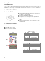
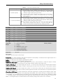
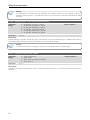
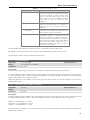
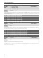
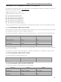
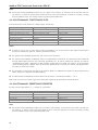
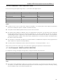
Accessory Kit 2 ACCESSORY KIT In order to make the Modbus-RTU communication possible with the SRW 01 smart relay, it is necessary to use a kit for Modbus-RTU communication, according to the description below. Information on this module installation can be obtained in the installation guide that comes with the kit. 2.1 MODBUS-RTU INTERFACE 2.1.1 Modbus-RTU Kit Composed by the Modbus-RTU communication module (figure at the left) and an installation guide. The interface follows the EIA-485 standard. The interface is electrically isolated and with differential signal, which grants more robustness against electromagnetic interference. The maximum distance for the connection of the devices is 1000 m. Network termination via switch, which must be turned on at the network extremes. 2.1.2 Connector Pin Functions Once the Modbus-RTU communication kit has been installed, the relay makes available two different connectors for the interface with the network: Female DB9 connector (XC15). 8-wire plug-in terminal strip (XC2). Table 2.1 – 8-wire plug-in terminal strip (XC2) pinout for the Modbus-RTU interface XC15 Pin A B PE BK BU SH WH RD Signal A B PE BK BU SH WH RD Function A-Line(-) B-Line(+) Protection Earth (shield) Not used by Modbus Not used by Modbus Not used by Modbus Not used by Modbus Not used by Modbus Table 2.2 – DB9 (XC15) connector pinout for the ModbusRTU interface XC2 NC = not connected. 8 Pin 1 2 3 4 5 6 7 8 9 Frame Signal NC NC B NC GND(ISO) +5V(ISO) NC A NC PE Function Not used by Modbus Not used by Modbus B-Line(+) (Modbus) Not used by Modbus Not used by Modbus Not used by Modbus Not used by Modbus A-Line(-) (Modbus) Not used by Modbus Protection Earth (shield)