1
TeleFlow™ 2-Run
(TF2RUN)
Load & Menus
&VMWXSP&EFGSGO
D4088 Issue:
March, 2001
The information in this document is subject to change without notice.
Every effort has been made to supply complete and accurate information.
However, Bristol Babcock assumes no responsibility for any errors that
may appear in this document.
Bristol Babcock does not guarantee the accuracy, sufficiency or suitability
of the software delivered herewith. The Customer shall inspect and test
such software and other materials to his/her satisfaction before using
them with important data.
There are no warranties, expressed or implied, including those of
merchantability and fitness for a particular purpose, concerning the
software and other materials delivered herewith.
Request for Additional Instructions
Additional copies of instruction manuals may be ordered from the address
below per attention of the Sales Order Processing Department. List the
instruction book numbers or give the complete model, serial or software
version number. Furnish a return address that includes the name of the
person who will receive the material. Billing for extra copies will be
according to current pricing schedules.
ACCOL is a trademark and Bristol is a registered trademark of Bristol
Babcock. Other trademarks or copyrighted products mentioned in this
document are for information only, and belong to their respective
companies, or trademark holders.
Copyright (c) 2001, Bristol Babcock, 1100 Buckingham St., Watertown,
CT 06795. No part of this manual may be reproduced in any form without
the express written permission of Bristol Babcock.
A Few Words About Bristol Babcock
For over 100 years, Bristol has been providing innovative solutions for the measurement and control industry.
Our product lines range from simple analog chart recorders, to sophisticated digital remote process
controllers and flow computers, all the way to turnkey SCADA systems. Over the years, we have become a
leading supplier to the electronic gas measurement, water purification, and wastewater treatment industries.
On off-shore oil platforms, on natural gas pipelines, and maybe even at your local water company, there are
Bristol Babcock instruments, controllers, and systems running year-in and year-out to provide accurate and
timely data to our customers.
Getting Additional Information
In addition to the information contained in this manual, you may receive additional assistance in using this
product from the following sources:
Contacting Bristol Babcock Directly
Bristol Babcock’s world headquarters are located at 1100 Buckingham Street, Watertown, Connecticut 06795
USA. Our main phone numbers are:
(860) 945-2200
(860) 945-2213 (FAX)
Regular office hours are Monday through Friday, 8:00AM to 4:30PM Eastern Time, excluding holidays, and
scheduled factory shutdowns. During other hours, callers may leave messages using Bristol’s voice mail
system.
Telephone Support - Technical Questions
During regular business hours, Bristol Babcock’s Application Support Group can provide telephone support
for your technical questions.
For technical questions regarding the TeleFlow 2-Run ACCOL load, other ACCOL products, Open BSI
Utilities, as well as Bristol’s Enterprise Server®/ Enterprise Workstation® products, call (860) 945-2286.
For technical questions about the TeleFlow unit, and other Network 3000 hardware call (860) 945-2502.
For technical questions about ControlWave call (860) 945-2244 or (860) 945-2286.
For technical questions regarding Bristol’s OpenEnterprise product, call (860) 945-2501 or e-mail
[email protected]
You can e-mail the Application Support Group at: [email protected]
i
The Application Support Group also maintains a bulletin board for downloading software updates to
customers. To access the bulletin board, dial (860) 945-2251 (Modem settings: 14.4K baud maximum, No
parity, 8 data bits, 1 Stop bit.)
For assistance in interfacing Bristol Babcock hardware to radios, contact Communication Technologies in
Orlando, FL at (407) 629-9463 or (407) 629-9464.
Telephone Support - Non-Technical Questions, Product Orders, etc.
Questions of a non-technical nature (product orders, literature requests, price and delivery information, etc.)
should be directed to the nearest regional sales office (listed below) or to your local Bristol sales office or
Bristol-authorized sales representative.
U.S. Regional Sales Offices
Watertown,CT (860) 945-2262
Birmingham, AL (205) 980-2010
Ontario, CA (909) 923-8488
Houston, TX (713) 685-6200
Principal International Sales Offices:
Bristol Babcock Ltd (UK): (441) 562-820-001
Bristol Babcock, Canada: (416) 675-3820
Bristol Meci SA (France): (33) 2-5421-4074
Bristol Digital Sys. Australasia Pty. Ltd. 61 8-9455-9955
BBI, S.A. de C.V. (Mexico) (525) 254-2131
Please call the main Bristol Babcock number (860-945-2200) if you are unsure which office covers your
particular area.
Visit our Site on the World Wide Web
For general information about Bristol Babcock and its products, please visit our site on the World Wide Web
at: www.bristolbabcock.com
Training Courses
Bristol Babcock’s Training Department offers a wide variety of courses in Bristol hardware and software at
our Watertown, Connecticut headquarters, and at selected Bristol regional offices, throughout the year.
Contact our Training Department at (860) 945-2343 for course information, enrollment, pricing, and
schedules.
ii
Who Should Read This Document?
This document is intended to be read by EGM 3530 TeleFlow™ users who are
using the standard software accompanying the TeleFlow™ .
It assumes that the TeleFlow™ has been installed, and that all network cabling has
been connected and tested.
EQUIPMENT APPLICATION WARNING
The user should note that a failure of this instrument or system, for whatever
reason, may leave an operating process without protection. Depending upon the
application, this could result in possible damage to property or injury to persons.
It is suggested that the purchaser review the need for additional backup
equipment or provide alternate means of protection such as alarm devices, output
limiting, fail-safe valves, relief valves, emergency shutoffs, emergency switches,
etc. If additional information is required, the purchaser is advised to contact
Bristol Babcock.
This document assumes familiarity with the following subjects:
"
"
"
The requirements of their particular process or application.
ACCOL programming. Anyone modifying the TeleFlow™ 2-run (TF2RUN)
software should be an experienced ACCOL programmer. For more
information, consider attending an ACCOL training class. Also see An
Introduction to ACCOL (document# D4056), the ACCOL Workbench User
Manual (document# D4051), and the ACCOL II Reference Manual
(document# D4044).
Universal Operator Interface (UOI) software. Anyone attempting to modify
the 2-run TeleFlow™ menus must be familiar with the UOI software tools.
See the UOI Configuration Manual (document# D5074) and the UOI
Operator Manual (document# D5075) for details.
iii
iv
Table of Contents
Chapter 1 - Introduction
1-1
Chapter 2 - Installing the Software
2-1
Chapter 3 - Using the TeleFlow™ 2-Run Menus (TF2RUN)
3-1
Chapter 4 - TeleFlow™ 2-Run ACCOL (TF2RUN) Load
4-1
Appendix A - Modifying the TeleFlow™ 2-Run ACCOL Load
A-1
v
BLANK PAGE
Chapter 1 - Introduction
What is the TeleFlow™ 2-Run (TF2RUN) ACCOL Load and Menus?
The TeleFlow™ 2-Run (TF2RUN) ACCOL Load and Menus is a collection of
software files on the TeleFlow™ diskette. They are used in conjunction with the
TeleFlow™ EGM 3530 Electronic Gas Measurement Computer, and fall into two
distinct categories:
"
"
TeleFlow 2-Run ACCOL (TF2RUN) Load. This ACCOL load contains
ACCOL modules specifically configured to perform various natural gas
calculations using an expanded I/O setup supporting 2 meter runs. It is
discussed in detail in Chapter 4 of this manual.
TeleFlow 2-Run (TF2RUN) Menus. A collection of menus, which may be run
using UOI on the PC, which are specifically configured to collect and display
data from the TeleFlow 2-Run (TF2RUN) ACCOL Load. These menus are
discussed in detail in Chapter 3 of this manual.
Modifying or Replacing the TeleFlow 2-Run ACCOL Load & Menus
The TeleFlow is a downloadable ACCOL device, therefore, the TeleFlow 2-Run
ACCOL Load can be modified or replaced with another compatible ACCOL load.
(See Appendix A for some notes about modifying the TeleFlow 2-Run ACCOL Load.)
For example, if the TeleFlow 2-Run ACCOL Load does not fit your particular
application, you may modify the .ACC file in ACCOL Workbench software
(available separately from Bristol Babcock,) re-build the ACL file, and download it
into the TeleFlow. For more information on ACCOL Workbench, see the ACCOL
Workbench User Manual (document# D4051).
Be aware, also, that the TeleFlow 2-run Menus are closely tied to the TeleFlow 2Run ACCOL Load. If you modify the standard load, or create a different load, you
will need to modify the associated menus, using the UOI programming tools
(available separately from Bristol Babcock). For more information on UOI, see the
UOI Configuration Manual (document# D5074).
TeleFlow™
1-1
2-Run (TF2RUN) Load and Menus
BLANK PAGE
Chapter 2 - Installing the Software
Installing UOI in DOS
Follow the instructions in the UOI Configuration Manual (document# D5074).
Installing the TeleFlow 2-Run Menus
Copy the files TF2RUN.UML, TF2RUN.UCL, and TF2RUN.UHL into your UOI
Installation directory.
ATOOLS.INI
If desired, certain configuration parameters for communications, etc., can be preconfigured in an ATOOLS.INI file. See the UOI Configuration Manual (document#
D5074) and the ACCOL II Reference Manual (document# D4044) for details.
Downloading the TeleFlow 2-Run ACCOL (TF2RUN) Load
The TeleFlow 2-Run ACCOL load may be loaded from the TeleFlow diskette using
the "Download ACL to ACCOL Node" poke point on the System Setup Menu. See
Chapter 3 for details.
TeleFlow™
2-1
2-Run (TF2RUN) Load and Menus
BLANK PAGE
Chapter 3 - Using the TeleFlow 2-Run Menus (TF2RUN)
Overview
The TeleFlow2-Run Menus (TF2RUN) is a collection of menus which are displayed
on a personal computer (PC) to allow a user to configure and monitor a TeleFlow
EGM 3530 Electronic Gas Measurement Computer running the TF2RUN.ACL 2
meter run ACCOL load. Depending upon the active security level, the TF2RUN
menus allow the user to:
Sign-on to the TeleFlow
Change the PC communication setup parameters
Download an ACCOL load file
Invoke menus to configure the TeleFlow for operation
Read current gas flow data for 2 meter runs, and totals for the station.
Set the date and time in the TeleFlow
Change the network address of the TeleFlow
Collect and display the Daily, Periodic, 15 Minute, and Audit Logs
PC Function Key Usage When Using UOI
The UOI program uses the PC function keys (keys [F1]...[F8]), the [Ins] key, arrow
keys, and the [Page Up] key as follows:
[F2]
Call up a help screen, if one is available.
[F3]
Examine signal details or advance to the next display.
[F4]
Back out to the previous menu level.
[F5]
Toggle Manual Inhibit/Enable.
[F6]
Back up one menu page.
[F7]
Toggle Control Inhibit/Enable.
[F8]
Move forward to another menu page.
[Ins]
The Insert key will activate a menu poke point (()or complete a
change in signal value.
[Page Up]
This key clears a displayed field - key is used prior to making value
changes.
Arrow keys Used to move between poke points.
TeleFlow™
3-1
2-Run (TF2RUN) Load and Menus
Chapter 3 - Using the TeleFlow 2-Run Menus (TF2RUN)
Throughout UOI, if a particular poke point is used to toggle between two selections,
the active selection appears capitalized, and the inactive selection appears in
lowercase letters. For example, "color/MONOCHROME" indicates that
MONOCHROME is the active selection.
Starting the UOI Program
The following command will start UOI:
UOI xxx
where
xxx
is the optional local address. If the local address is not
entered here, the Communication Setup Menus must be
used to define it, or it must be pre-defined in the
ATOOLS.INI file. NOTE: If connected to the local
port, any address is valid.
For example:
UOI 1
starts UOI and configures it to communicate with a local address of 1.
Setting the Local Address and Communication Parameters Up In Advance
If desired, much of the start-up routine for UOI can be automated. For example, the
local address, communication parameters, modem information, and even the
username and password can be specified, in advance, in the ATOOLS.INI file,
thereby simplifying the start-up process for the operator. See Chapter 2 for
information on the ATOOLS.INI file, as well as the ’ATOOLS.INI’ section of the
ACCOL II Reference Manual (document# D4044).
TeleFlow™
3-2
2-Run (TF2RUN) Load and Menus
Chapter 3 - Using the TeleFlow 2-Run Menus (TF2RUN)
UOI Startup Menu
UNIVERSAL OPERATOR INTERFACE
Bristol Babcock Inc.
1100 Buckingham St.
Watertown, CT
ˆ COLOR / monochrome
To
Continue, depress 'NEXTDISPLAY' (F3)
copyright © 1991-1995 Bristol Babcock Inc.
The first menu to appear, typically, is the UOI Startup Menu. If you are using a
monochrome monitor, toggle the COLOR/monochrome poke point, by pressing the
[Ins] key, otherwise leave it at the default, which is for color monitors.
Press the [F3] key to bring up the next display. If you have only one set of UOI
menus (UML files) you will go to the Sign-On Menu (see page 3-4), otherwise, you
will go to the UML File Select Menu (see page 3-3).
UML File Select Menu
If you have more than one set of menus (UML files) in the UOI installation
directory on your PC, this menu is accessed from the Startup Menu (see page 3-3)
by pressing [F3]. Otherwise, you can call it up from the "Select Menu
Specification File" poke point on the System Set-up Menu (see page 3-5).
UML File Select Menu
UML directory: C:\UOI________________________
´
´
´
TF2RUN 3530 MENUS
MY CUSTOMIZED MENUS
SINGLE RUN MENUS
´ Exit
Since you want to use the 2-run TeleFlow menus, you should always
choose the TF2RUN 3530 MENUS poke point. (This will activate the files
TF2RUN.UCL, TF2RUN.UML, and TF2RUN.UHL.)
TeleFlow™
3-3
2-Run (TF2RUN) Load and Menus
Chapter 3 - Using the TeleFlow 2-Run Menus (TF2RUN)
Signing On to the TeleFlow (Sign-On Menu)
SIGN-ON MENU
ˆ
Security Sign-on
´
Off-line Mode
´
System Set-up
´
Exit
The Sign-On Menu provides poke points for signing onto UOI, calling up the off-line
menus, configuring the communications system, and exiting from UOI.
Typically, this menu will appear after the Startup Menu. If there were multiple
UML files to choose from, however, the UML File Select Menu appears first (see
page 3-3).
If you want to use the off-line configuration menus (which do not require connection
to the TeleFlow) but, as a consequence, do NOT allow any access to live data, choose
the "Off-Line Mode" poke point, and skip to page 3-67.
If you intend to use on-line mode, which is the most common arrangement, you may
need to change the system communications setup first. To do so, move the cursor to
the "System Set-up" poke point, and press [Ins]. Follow the directions on page 3-5
to change the system setup.
If the system setup does not need to be changed, you may sign on as follows:
1. Move the cursor to the "Security Sign-On" poke point and press [Ins]. UOI will
read all the allowed names and passwords from the TeleFlow into the PC, and
then display a prompt for an operator name.
2. When the "Enter Operator Name" prompt appears at the bottom left of the
screen, type in the operator name and press [Ins]. UOI will compare the name to
those read from the TeleFlow and either accept or reject the name. The factory
default name is SYSTEM. (Be sure to use the [Ins] key, not [Enter]. If the name
is correct, you will be prompted for the password).
3. When the "Password" prompt appears, type in the password. The default
password for SYSTEM is 666666. To maintain security, the password characters
will not be visible as they are typed. Press [Ins] to enter the password; UOI will
compare it to the one associated with the accepted name and either accept or
reject the password.
TeleFlow™
3-4
2-Run (TF2RUN) Load and Menus
Chapter 3 - Using the TeleFlow 2-Run Menus (TF2RUN)
NOTE:
The security level associated with your username/password
(or security code) will determine which functions are
accessible within UOI. Certain menus shown in this manual
will NOT be visible for those users who have signed on at less
than the highest security level.
Once you have signed on successfully, you will see one of two menus, depending
upon your security level. Users signed on at security level 1, 2, or 3 will see the
Station Main Menu (see page 3-9). Users signed on at security level 4, 5, or 6 will
see the On Line System Menu (see page 3-24).
Using the System Setup Menu
This menu may be accessed through the "System Set-up" poke point on the Signon Menu (see page 3-4).
SYSTEM SET-UP MENU
´
Select Menu Specification File
´
Download ACL to ACCOL Node
´
Reconfigure Communications Set-up
ˆ
Exit
The "Select Menu Specification File" poke point calls up the UML File Select
Menu (see page 3-3).
The "Download ACL to ACCOL Node" poke point allows you to download an
ACCOL Load File (.ACL) to the attached TeleFlow (provided that communications
have already been successfully established.)
The "Reconfigure Communications Set-up" poke point activates the BBI Tools
Communications Setup Menus, which allow communications to be configured. (see
page 3-6).
TeleFlow™
3-5
2-Run (TF2RUN) Load and Menus
Chapter 3 - Using the TeleFlow 2-Run Menus (TF2RUN)
Establishing Communications with the TeleFlow
BBI TOOLS COMMUNICATIONS SETUP MENU
HELP (F2 Key) Available
ACTIONS
ˆ
Identify Local Node - Node Attached to PEI Hardware
´
Identify Global Node - Target node is not Local Node
´
Define Local Link - Baud Rate, Port, Modem Usage
´
Issue Node Routing Table / Time Sync
STATUS
Local Node Address:
127
Baud Rate: 9600
Timeout:
NO MODEM
1 Seconds
Comm Port: COM1:
Press NEXT DISPLAY Key (F3) to enter program with Comm System as defined
The address of the TeleFlow must be specified in UOI. The address and other
parameters are entered via the Communication Setup Menus discussed in this
section. Either local or global communications are supported.
NOTE
Certain communications setup parameters may, if desired, be
pre-defined in a text file called ATOOLS.INI. See Chapter 2
for more information; also see the ’ATOOLS.INI’ section of the
ACCOL II Reference Manual (document# D4044).
Initiating Local Communications
If your computer is directly connected to the TeleFlow Local Communications Port,
proceed as follows:
Move the cursor to the "Identify Local Node" poke point, then press [Ins].
The BBI Tools Local Communications Setup Menu will appear (see below).
This menu page allows the operator to reconfigure the Local Address, Local
Node Name and the Expanded BSAP Group Address (0-127 default is 0).
This menu also provides a poke point for examining the NETTOP File (to
aid in node name determination).
TeleFlow™
3-6
2-Run (TF2RUN) Load and Menus
Chapter 3 - Using the TeleFlow 2-Run Menus (TF2RUN)
BBI TOOLS LOCAL COMMUNICATIONS SETUP MENU
HELP (F2 Key) Available
___1
Local Address of Node attached to PEI/NM Hardware
____
Local Node Name - Not always required - see HELP
___0
Expanded BSAP Group Number
´
Examine Nettop file (to aid node name determination)
Press BACK DISPLAY Key (Function Key 4)
to return to the main communications menu.
Type in the local address (1 is the factory default), press [Ins], then press
[F4]. The following message will be displayed at the lower left corner of the
menu: ’Time Sync/NRT Sent’. This message indicates that the PC’s time
and networking information have been sent to the TeleFlow.
Initiating Global Communications
If you are communicating through the network (global communications), use this
procedure:
The UOI program will communicate globally through the master node of a
network to any 33XX node which is a slave to a lower level node. Select the
"Identify Global Node" poke point. The BBI Tools Global Communications
Setup Menu will appear (see below). Specify the 33XX’s node name as it
appears in the NETTOP files. Note: A NETTOP File poke point is provided
for examining the NETTOP files.
BBI TOOLS GLOBAL COMMUNICATIONS SETUP MENU
HELP (F2 Key) Available
____
Global Target Node Name
´
Examine Nettop file (to aid node name determination)
Press BACK DISPLAY Key (Function Key 4)
to return to the main communications menu.
After entering the node name, press [F4] .
TeleFlow™
3-7
2-Run (TF2RUN) Load and Menus
Chapter 3 - Using the TeleFlow 2-Run Menus (TF2RUN)
Setting The Baud Rate, Port & Modem Usage Parameters
The PC Serial Port is set to 19200 baud through COM1 by default. To change the
default communications port or the baud rate, select the "Define Local Link" poke
point and press [Ins]; the BBI Tools Communications Port Setup Menu (shown
below) will appear.
BBI TOOLS COMMUNICATIONS PORT SETUP MENU
HELP (F2 Key) Available
Selected Baud Rate: 9600
´ 150 BAUD
´ 300 BAUD
´ 600 BAUD
BAUD
Timeout: _1 Seconds
´ 1200 BAUD
´ 2400 BAUD
´ 4800 BAUD
Selected Comm Port: COM1:
´ 9600 BAUD
´ 19200 BAUD
´ 38400 BAUD
3308 Node Type: ´ yes/NO
ˆ COM1: ´ COM2: ´ COM3: ´ COM4:
Download Retry: _5
Modem: NO MODEM
´ None
´ BBI FSK/HEADBAND
´ UDS 202S/D
´ HayesSmart
´ Help
Press BACK DISPLAY Key (Function Key 4)
to return to the main communications menu.
Use the poke points on this menu to change the port and baud rate selections as
required. ’19200 baud’ and ’No Modem’ are the default settings and should always
be used with the TeleFlow.
When entries on this screen are complete, press [F4] to return to the BBI Tools
Communications Setup Menu (see page 3-6). Press [F3] to change all the settings in
the PC to the new settings. UOI will then attempt to communicate with the
TeleFlow . If communications are successfully established, the Sign-On Menu will
appear on the screen (see page 3-4).
TeleFlow™
3-8
2-Run (TF2RUN) Load and Menus
Chapter 3 - Using the TeleFlow 2-Run Menus (TF2RUN)
Station Main Menu (Security Levels 1,2, or 3)
For users successfully signed on at security level 3 or below, the Station Main Menu
is the first menu to appear.
STATION M A I N M E N U
ˆ RUN 1 MAIN MENU
´ RUN 2 MAIN MENU
´ Sign-off and Exit
The poke points at the bottom of the menu allow access to meter-run-specific data
on the Run x Main Menus.
Run x Main Menus (Security Level 1, 2, or 3)
These menus (specific to either Run 1 or Run 2) display certain data for the meter
run, and also include poke points to call up logs, plot trend data, or view alarms.
RUN 1
M A I N
M E N U
Meter type
DP In Use
Temp In Use
Flow Rate/Hr
Uncorr Volume Tdy
Volume Today
Backflow Today
TURB
0.00
0.00
0
0
0
0.00
Orifice Diameter
Gravity
CO2 Content
2.000
0.6000
0.0000
´
´
Log Utilities
Plot Trend Data
´
´
INH2O
DEGF
MSCFH
MACF
MSCF
MINS
INCHES
MOLE%
View Alarms
Maintenance
Meter Factor
SP In Use
1.0
0.00
Flow Rate/Day
Uncorr Volume Ydy
Volume Yesterday
Backflow Yesterday
Pipe Diameter
Heating Value
N2 Content
´
PPACF
PSIG
0
0
0
0.00
4.026
1000.0
0.0000
MSCFD
MACF
MSCF
MINS
INCHES
BTU/CF
MOLE%
Sign-off and Exit
The poke points function as follows:
Log Utilities
TeleFlow™
Calls up the Run x Log Utilities Menu. (See page 3-10)
3-9
2-Run (TF2RUN) Load and Menus
Chapter 3 - Using the TeleFlow 2-Run Menus (TF2RUN)
Plot Trend Data
Calls up a trend plot of P, DP, and T data for this run. (See page
3-11 for details).
View Alarms
Calls up the Run x Alarm Status Information Menu (see page 314).
Maintenance
Calls up the Maintenance Operations Menu (see page 3-17).
Run x Log Utilities Menu (All Security Levels)
Log Collect, Convert and Display functions are all included on the Log Utilities
Menu. The Log Utilities Menu is accessible to level 1,2, and 3 users by selecting the
"Log Utilities" poke point on the Run x Main Menu (see page 3-9), or to level 4 and
above users by selecting the appropriate "Run x Logs" poke point on the Station
Log Utilities Menu (see page 3-36) or the "Log Collection" poke point on the
appropriate Run x Function Menu (see page 3-37).
RUN 1
LOG UTILITIES MENU
Meter ID is: RSP1
ˆ
COLLECT
View/Change Drive/Directory
CONVERT
DISPLAY
Combo Log
´
(Daily, Periodic, Trend, Audit, Config)
´
´
Daily Log
´
´
´
Hourly Log
´
´
´
Trend Data Log
´
´
´
Alarm/Event Log
´
´
´
´
Sign-off and Exit
This menu presents the user with a matrix of menu poke-points describing what
functions may be performed. In addition, the user may change the default disk
drive on the log select menus via the "View/Change Drive Directory" poke point.
It should be noted that "Combo" Logs include the 15 Minute Trend Data.
COLLECT Poke Points: Collects a specific log and appends it to an existing file in
binary format.
CONVERT Poke Points: Converts collected binary data to ASCII format, and
stores it in an ASCII Text File on disk.
TeleFlow™
3-10
2-Run (TF2RUN) Load and Menus
Chapter 3 - Using the TeleFlow 2-Run Menus (TF2RUN)
DISPLAY Poke Points: Displays text from the ASCII text file on the screen.
The Meter ID is used as the file name for all log binary and text files.
Trend Plot (All Security Levels)
Trend plots of DP (differential pressure), P (static pressure), and T (temperature)
data can be displayed for security levels 1 through 3 users by selecting the "Plot
Trend Data" poke point on the Run x Main Menu (See page 3-9) or for level 4 and
above users by selecting the "Plot Trend Data Run x" poke point on the Run x
Current Gas Flow Information Menu (see page 3-39).
The screen plot will appear similar to the figure on the next page. When the plot is
initially called up on the screen, UOI will attempt to show all of the available data.
Depending upon your application, this may result in too much data being
compressed in too small an area. To adjust this, use the "Zoom In" poke points, to
concentrate on a smaller portion of the plot; this may make the plot easier to read.
The Trend Data plot includes three traces, one for differential pressure (DP) one for
pressure (P) and a third for temperature (T). Individual traces can appear in a
variety of styles and/or colors. In the plot above, the DP trace uses squares, the P
trace uses circles, and the T trace uses a line.
There are several poke points included with each screen plot, which may be used to
alter the way data is presented.
SHIFT PAGE LEFT
This poke point shifts the period for data being plotted back in time, to show
older data.
SHIFT COLUMN LEFT
This poke point performs the same function as SHIFT PAGE LEFT, except in
smaller increments.
SHIFT PAGE RIGHT
This poke point shifts the period for data being plotted forward in time, to
show more recent data.
TeleFlow™
3-11
2-Run (TF2RUN) Load and Menus
Chapter 3 - Using the TeleFlow 2-Run Menus (TF2RUN)
SHIFT COLUMN RIGHT
This poke point performs the same function as SHIFT PAGE RIGHT, except
in smaller increments.
ZOOM OUT 1.2X, 2X, 5X
The "zoom out" poke points increase the number of data points which will be
displayed on the plot, but compresses the amount of space between data
points. Zooming out results in a longer time-scale of data points being
displayed in a given area of the screen.
ZOOM IN 1.2X, 2X, 5X
The "zoom in" poke points decrease the number of data points which will be
displayed on the plot, but increases the amount of space between data points.
Zooming in makes it easier to examine individual data points in the plot.
SCALE MODE: AUTO/MANUAL
The "Scale Mode" poke point toggles the mode used to determine the 0% and
100% scale values for an individual trace on the plot. Each trace has its own
TeleFlow™
3-12
2-Run (TF2RUN) Load and Menus
Chapter 3 - Using the TeleFlow 2-Run Menus (TF2RUN)
scale mode poke point. If there are less than 4 traces for this plot, the word
’unused’ will appear next to the extra poke point(s.)
When AUTO is selected, the word AUTO is capitalized, and manual is shown
in lowercase letters. When MANUAL is selected, the word MANUAL is
capitalized, and the word auto is shown in lowercase letters.
AUTO
The 0% value is automatically set to the value of the smallest data value for
this trace currently being displayed on the screen. The 100% value is
automatically set to the value of the largest data value for this trace currently
being displayed on the screen. These values are displayed in the 0% and 100%
fields at left, and are dynamically updated if the SHIFT poke points are used
to call up different time scales of data. AUTO mode ensures that the trace for
a particular signal will never go above the 100% line, or below the 0% line on
the screen.
MANUAL
Manual mode requires the operator to enter 0% and 100% data values for each
individual poke point. Data values which are outside the 0 and 100% range
defined by these values may not be visible on the screen, depending upon how
far above or below the range, the value has gone.
SHOW/HIDE
Each trace has its own SHOW/HIDE poke point, which is used to turn on/off
the display of a particular trace on the plot. When SHOW is selected, the trace
will appear. When HIDE is selected, the trace is omitted from the plot.
TeleFlow™
3-13
2-Run (TF2RUN) Load and Menus
Chapter 3 - Using the TeleFlow 2-Run Menus (TF2RUN)
Run x Alarm Status Information Menus (All security levels)
These displays allow the user to view alarms which have been generated at the
TeleFlow. They are accessible for users with security level 1 to 3 from the "View
Alarms" poke point on the appropriate Run x Main Menu (see page 3-9), or for
users with security level 4 and above from the "Alarm Status and Configuration"
poke point on the Run x Functions Menu (see page 3-37).
The Alarm Status Information Menu consists of three pages. Page 1 presents
current alarm data for various TeleFlow functions and measurements.
RUN 1
ALARM STATUS INFORMATION
Page 1 of 3
DIFF PRESS
ALARM
STATIC PRESS
ALARM
FLOWING TEMP
ALARM
FLOW RATE
OKAY
BACKFLOW
LOW DP CUTOFF
BACKFLOW ALARM DELAY
CLEAR_
ME CE AE
ACTIVE
ME CE AE
___10 SECS
TRANSMITTER FAILURE
SENSOR CHECKSUM
CLEAR_
OK____
ME CE AE
ME CE AE
AGA8 CALC ERROR
OFF___
ME CE
PRESS F8 TO CONFIGURE ALARMS
To enable (E) or inhibit (I) a Manual (M), Control (C) or Alarm (A) Status Bit
(associated with page 3 of the Alarm Configuration Menu), press [F3] (with the
cursor on the highlighted state associated with the logical signal in question, i.e.,
Low DP Cutoff, Backup Battery, AGA8 Calc Error or Self-Check Failure. The menu
which appears will allow the user to examine and change signal details.
Pages 2 and 3 provide analog alarm configuration information. They allow the user
to configure alarm deadbands and alarm limits. To change an alarm configuration
deadband or limit value, enter the new value directly on the display (page 2 or 3) or
press [F3] (with the cursor set on the highlighted value in question). The menu
which appears will allow the user to examine/change signal details.
Run 1 uses the integral transducer thus the Run 1 menus show alarms related to
the transducer which do not appear on menus for the other run.
TRANSMITTER FAILURE
TeleFlow™
The integral transducer is not responding to
data requests.
3-14
2-Run (TF2RUN) Load and Menus
Chapter 3 - Using the TeleFlow 2-Run Menus (TF2RUN)
SENSOR CHECKSUM
The on-board serial EEPROM containing
compensation data has undergone a data
change.
RUN 1 ALARM CONFIGURATION
Page 2 of 3
DIFFERENTIAL
PRESSURE
STATIC
PRESSURE
TEMPERATURE
CURRENT VALUE
___0.00 INH2O
___0.00 PSIG
___0.00 DEGF
LOW ALARM DEADBAND
LOW ALARM
LOW LOW ALARM
___3.00 INH2O
__10.00 INH2O
___0.00 INH2O
__10.00 PSIG
_100.00 PSIG
___0.00 PSIG
___3.00 DEGF
__50.00 DEGF
__32.00 DEGF
HIGH ALARM DEADBAND
HIGH ALARM
HIGH HIGH ALARM
__10.00 INH2O
_250.00 INH2O
_300.00 INH2O
__50.00 PSIG
1500.00 PSIG
2000.00 PSIG
__10.00 DEGF
_150.00 DEGF
_250.00 DEGF
PRESS F8 FOR MORE ALARMS
RUN 1 ALARM CONFIGURATION
USE PgUp TO CLEAR FIELD
Page 3 of 3
FLOW RATE
CURRENT VALUE
____0.00 MSCFH
LOW ALARM DEADBAND
LOW ALARM
LOW LOW ALARM
__50.00 MSCFH
_____0.0 MSCFH
_____0.0 MSCFH
HIGH ALARM DEADBAND
HIGH ALARM
HIGH HIGH ALARM
__50.00 MSCFH
__3000.0 MSCFH
__5000.0 MSCFH
USE PgUp TO CLEAR FIELD
Deadbands and Limits:
- A deadband is a ’no detect’ zone around the alarm limit to prevent multiple
alarms if the signal oscillates at the threshold of the alarm limit.
-
Low Alarm, Low Low Alarm, High Alarm and High High Alarm limit data fields
represent the alarm setpoints. Note: When configuring an alarm signal,
TeleFlow™
3-15
2-Run (TF2RUN) Load and Menus
Chapter 3 - Using the TeleFlow 2-Run Menus (TF2RUN)
provide an adequate non-alarm zone to ensure that the signal is not in a
continuous alarm state.
An alarm condition occurs when the signal value exceeds the alarm limit. The
alarm remains activated until the signal returns to the non-alarm range defined
by the alarm limits and deadbands.
By default, signals that are in the alarm state are displayed on the LCD Display.
Alarms may be inhibited from appearing on the LCD Display via the "ALARM
DISPLAY" poke point on the Station Configuration and Inputs/Outputs Menu (see
page 3-27).
TeleFlow™
3-16
2-Run (TF2RUN) Load and Menus
Chapter 3 - Using the TeleFlow 2-Run Menus (TF2RUN)
Run x Maintenance Operations Menu (Requires Security Level 1, 2, or 3)
The Run x Maintenance Operation Menu is accessible from the "Maintenance"
poke point on the Run x Main Menu (see page 3-9).
RUN 1
MAINTENANCE OPERATIONS MENU
ˆ
Transmitter 1 Calibration
´
Perform Plate Change
´
Sign-off and Exit
The Maintenance Operations Menu provides three poke points; "Transmitter
Calibration" which activates the Verify/Calibrate menus, (see page 3-18),
"Perform Plate Change" which activates the Orifice Plate Change Menu (see page
3-17), and "Sign-Off and Exit".
The first two poke points activate their related menus after first setting signals in
the load to ON; these signals are set OFF when the related menu is exited. This is
done to provide a log record of maintenance activity.
Run x Orifice Plate Change
When "Perform Plate Change" is selected, the DP, P, and T inputs are ’frozen’ at
their present value. They are ’unfrozen’ when the menu is exited. The following
notification is displayed.
RUN 1
ORIFICE PLATE CHANGE
The DP, SP, and T values have been Frozen to their current
values. These values will be Unfrozen upon exiting from
this menu.
When the Orifice Plate has been changed, enter the new value
for the Orifice Plate Diameter below and then exit this
menu.
_________________________________________________________________________
Orifice Plate Diameter:
TeleFlow™
__2.000
3-17
INCHES
2-Run (TF2RUN) Load and Menus
Chapter 3 - Using the TeleFlow 2-Run Menus (TF2RUN)
Transmitter x Calibration Menus (Any security Level)
The Transmitter Calibration/Verification Menu is accessed from the "Transmitter
Calibration" poke point on either the Run x Functions Menu (see page 3-37) or the
Maintenance Operations Menu (see page 3-17). This menu allows the user to verify
calibration procedures, to perform calibration procedures, and to configure
Damping & Mode Control.
Selection of a verification poke point automatically turns the calibration mode
signal ON and invokes the appropriate Verification menu. When the calibration
mode signal is turned ON, the TeleFlowautomatically freezes the DP, P, and T
variables at there current value. Verification Menus are identical except for the
variable being verified.
The Calibration Menus have been customized to aid the Technician or Engineer
who is performing or checking TeleFlow calibration. A Help Menu can be accessed
by pressing [F2]. The Help Menu displayed is dependent upon the screen you are in
when you press the [F2] key.
The Damping and Mode Control Menu provides access to the DP Floating Point
Damping Enable/Disable feature and the DP Floating Point Damping Time
constant.
Verification
The Verification menus for DP, P, and T are virtually identical except for the
variable being verified. Only the DP Verification menu will be described in this
document.
The Verification menu contains the procedure describing how to perform the
verification process. The live value for the variable being processed is displayed
below the procedure. The verification procedure consists of applying a known test
value to the variable being verified and waiting for the live value to stabilize. The
[Enter] key is used to indicate that this has occurred.
When the [Enter] key is pressed, the user is prompted to enter the test value
applied to the input. Entering the applied value causes an Audit/Event record to be
written to the TeleFlow. This Audit/Event record contains an indication of which
variable is being verified, the applied test value, and the actual live value.
The user may apply as many test values as needed.
TeleFlow™
3-18
2-Run (TF2RUN) Load and Menus
Chapter 3 - Using the TeleFlow 2-Run Menus (TF2RUN)
TRANSMITTER CALIBRATION / VERIFICATION
VERIFICATION PROCEDURES:
( Verify Differential Pressure (DP) Calibration
( Verify Static Pressure (P) Calibration
( Verify Temperature (T) Calibration
CALIBRATION PROCEDURES:
( Calibrate Differential Pressure (DP)
( Calibrate Static Pressure (P)
( Calibrate Temperature RTD (T)
( Damping and Mode Control
VERIFY DIFFERENTIAL PRESSURE INPUT CALIBRATION
Procedure:
1 - Apply test value to DP, when live value is steady press ENTER.
2 - Enter the test value applied.
3 - Repeat steps 1 & 2 as required. (Typically, use test values of
0, 50, 100, 80, 20, 0 percent of scale.)
_____________________________________________________________________
DP Live Value: __________
________
Apply a test value to DP, when live value is steady press ENTER
See help menu (F2) for verification procedure.
TeleFlow™
3-19
2-Run (TF2RUN) Load and Menus
Chapter 3 - Using the TeleFlow 2-Run Menus (TF2RUN)
Calibration of Differential Pressure
The differential pressure sensor of the transmitter is checked and calibrated as
follows:
1. Vent the HI and LO input ports of the DP body to atmosphere to obtain a 0%
differential.
2. Move the cursor to the "CALIBRATE ZERO" poke point and observe the
"LIVE DP VALUE".
DIFFERENTIAL PRESSURE (DP) CALIBRATION
LIVE DP VALUE: 0.000 inch H20
) CALIBRATE ZERO
) CALIBRATE OPERATING SPAN
See help menu (F2) for calibration procedure.
3. Once the reading in the "LIVE DP VALUE" has stabilized, press the [Ins]
key to calibrate the DP Zero.
4. Connect a precision test pressure source (+.025%) to the HI port.
5. Apply a pressure to the HI port that is 15% to 100% of the transmitter’s
pressure range.
Example 1
If the differential range of the TeleFlow is 0 to 150 in H2O, 100% of the
range would be equivalent to 150 inH2O. Any differential pressure (as-lowas 22.5 inH2O) could be used.
6. Move the cursor to the "CALIBRATE OPERATING SPAN" poke point.
7. Observe the "LIVE DP VALUE" field and note the applied pressure.
8. Once this value has stabilized, press the [Ins] key.
TeleFlow™
3-20
2-Run (TF2RUN) Load and Menus
Chapter 3 - Using the TeleFlow 2-Run Menus (TF2RUN)
9. Type in the applied pressure value in response to the prompt and press the
[Ins] key. Zero and Operating Span calibration is complete.
Note: All linearization has been performed at the factory and is not
required.
Calibration of Static Pressure
Static pressure calibration is performed with a test pressure applied to the HI and
LO port of the DP body (the SP sensor is connected to the HI side of the DP body).
This procedure is nearly identical to that described above for the Differential
Pressure except that the test pressure source must be capable of providing up to the
maximum value of the SP sensor (500 or 2000 psi types). The "CALIBRATE
ZERO" poke point identified in the Static Pressure (SP) Calibration Menu is
checked with no pressure applied, while the "CALIBRATE OPERATING SPAN"
poke point is checked with pressures from 15% to 100% of the upper range limit of
the SP sensor.
STATIC PRESSURE (SP) CALIBRATION
LIVE SP VALUE:
0.000 PSI
(
CALIBRATE ZERO
(
CALIBRATE OPERATING SPAN
See help menu (F2) for calibration procedure.
TeleFlow™
3-21
2-Run (TF2RUN) Load and Menus
Chapter 3 - Using the TeleFlow 2-Run Menus (TF2RUN)
Calibration of RTD Temperature
TEMPERATURE CALIBRATION OF RTD
(
SELECT DISPLAY UNITS
LIVE READING:
+76.031 Degrees F
(
CALIBRATE ZERO (AT 100 OHMS)
(
CALIBRATE OPERATING SPAN
(
ADJUST LIVE READING
See help menu (F2) for calibration procedure.
1.
Disconnect the regular RTD sensor and connect a 100 Ohm (" .025%)
precision resistor across the RTD terminals (which is equivalent to 32EF).
2. Move the cursor to the "CALIBRATE ZERO" poke point.
3. Observe LIVE T VALUE.
4. When LIVE T VALUE stabilizes press [Ins] key to calibrate the RTD Zero.
5. Disconnect the resistor of step 1 and connect a 140 Ohm (" .025%) precision
resistor across the RTD terminals (which is equivalent to 220EF).
6. Move the cursor to the "CALIBRATE OPERATING SPAN" poke point.
7. Observe LIVE T VALUE.
8. When LIVE T VALUE stabilizes press [Ins] key to calibrate the RTD
Operating Span.
9. If after re-connecting the unit to the process it is determined that the number
in the LIVE T VALUE field does not correlate with that measured by an
external process monitoring device, offset compensation may be performed.
Select the "ADJUST LIVE READINGS" poke point and press [Ins]. This
allows a linear shift of the RTD temperature span, e.g., if at 68EF the Live
TeleFlow™
3-22
2-Run (TF2RUN) Load and Menus
Chapter 3 - Using the TeleFlow 2-Run Menus (TF2RUN)
Reading value is 68.5EF, the error is .5EF. To correct this error enter 68E at
the prompt.
Damping And Mode Control (Requires Security Level 4 or higher)
The TeleFlow’s firmware provides output damping selections which can be set on
the Damping and Mode Control Menu.
DAMPING AND MODE CONTROL
) DP Floating Point Damping:
enabled/DISABLED
) DP Floating Point Damping Time:
0.6 Secs
The "DP Floating Point Damping Time" controls the rate at which the output
responds to a given change of input. It is used to slow down the output response to a
rapid or oscillatory change of the measured variable. The indicated value changes
63% of the difference between the "present measured pressure" and the "present
indicated pressure" in one damping time period. It would take 5 times the DP
Floating Point Damping Time for the "present indicated pressure" to equal the
"present measured pressure" (if a change in the "present measured pressure" didn’t
occur). An increase in the DP Floating Point Damping Time results in an increase
in smoothing the input data.
TeleFlow™
3-23
2-Run (TF2RUN) Load and Menus
Chapter 3 - Using the TeleFlow 2-Run Menus (TF2RUN)
Using the On-Line System Menu (Security Levels 4, 5, or 6)
For users who have successfully signed on at Security Level 4 or above, the On-Line
System Menu will be the first menu to appear.
The On-Line System Menu provides access to both station menus and run-specific
menus. In general, Station Menus contain summary information about the entire
station, such as flow totals, or configuration data which is common to both meter
runs; Run Menus, contain more detailed information about either one of the two
independent meter runs, Run 1 or Run 2.
Details on the individual functions/menus accessible from the On-Line System
Menu will be discussed in the remainder of this chapter.
ON-LINE SYSTEM MENU
´
Station Items
ˆ
Run 1 Items
´
Run 2 Items
´
System Items
Note: No Gas Calculations will be done if Config errors exist
Config error 1 OFF___
Config error 2 OFF___
Station Items
this poke point calls up the Station Menu. (See page 3-25).
NOTE: The Station Menu should NOT be confused with the
Station Main Menu used at lower security levels).
Run x Items
these poke points call up the Run x Functions Menu for
either Run 1 or Run 2. (See page 3-37).
System Items
this poke point calls up the System Status and Control
Menu. (See page 3-55).
TeleFlow™
3-24
2-Run (TF2RUN) Load and Menus
Chapter 3 - Using the TeleFlow 2-Run Menus (TF2RUN)
Station Menu (Security Level 4, 5, or 6)
STATION MENU
ˆ
Current Gas Data
´
Configuration and Inputs
´
Alarm Status and Configuration
´
Run Switching
´
PID Control
´
Log Collection
The Station Menu contains poke points which allow access to data which is common
to the entire station (both runs).
Current Gas Data
Calls up the Station Instantaneous Gas Flow
Readings Menu (see page 3-26).
Configuration and Inputs
Calls up the Station Configuration and
Inputs/Outputs Menu (see page 3-27).
Alarm Status and Configuration
Calls up the Station Alarm Status Information
Menus (see page 3-29).
Run Switching
Calls up the Run Switching Menu (see page 331).
PID Control
Calls up the Station PID Flow Controller
Menu (see page 3-32).
Log Collection
Calls up the Station Log Utilities Menu (see
page 3-36).
TeleFlow™
3-25
2-Run (TF2RUN) Load and Menus
Chapter 3 - Using the TeleFlow 2-Run Menus (TF2RUN)
Current Gas Flow Information - Station Summary (Security 4,5, or 6)
To see a summary of gas flow information for the entire station, including station
flow totals, call up the Station Instantaneous Gas Flow Readings Menu, accessible
via the "Current Gas Data" poke point on the Station Menu (see page 3-25).
STATION
METER TYPE
DIFF PRES
STAT PRES
TEMP
INSTANTANEOUS GAS FLOW READINGS
RUN1
ORIF
0.00 INH2O
0.00 PSIG
0.00 DEGF
FLOW RATE
FLOW RATE
ENERGY RATE
VOLUME CURR
ENERGY CURR
VOLUME TODAY
ENERGY TODAY
FLOW TIME
NOMINATION ENABLE
NOMINATION TOTAL
TeleFlow™
RUN2
ORIF
0.00 INH2O
0.00 PSIG
0.00 DEGF
0.00 MSCFH
0.00 MSCFD
0.00 MMBTUH
STATION
0.00 MSCFH
0.00 MSCFD
0.00 MMBTUH
0.0
0.0
0.0
0.0
0.0
0.0
0.0
0.0
0
0
DISABL
0.00 MSCFH
0.00 MSCFD
0.00 MMBTUH
0.0
0.0
0.0
0.0
MSCF
MMBTU
MSCF
MMBTU
MINS
DISABL
0.0
0.0
3-26
2-Run (TF2RUN) Load and Menus
Chapter 3 - Using the TeleFlow 2-Run Menus (TF2RUN)
Station Configuration and Inputs/Outputs Menu (Security Level 4, 5, or 6)
These menus allow the user to view/set certain configuration constants, and to
configure auxiliary analog inputs and discrete inputs/outputs. The first page is
accessed via the "Configuration and Inputs" poke point on the Station Menu (see
page 3-25). The second and third pages are accessible by pressing the [F8] key.
STATION CONFIGURATION AND INPUTS/OUTPUTS
UNIT ID
9999________________
METER ID 1
Page 1 of 3
Unnamed1
CALCULATION INTERVAL
____30
CONTRACT HOUR _____7
ALARM LCD DISPLAY
OFF___
DISPLAY RATE _____2
LOAD DATE
LOAD ID
27-Feb-2001 09:40
ATF2R2
VERS
VERS: 0001
METER ID 2
Unnamed2
(Common to both runs)
RUN 1 PRIMARY CLEAR
FILE: TF2RUN
10.20
POWER INPUT 1
12.24 VOLTS
POWER INPUT 2
0.16 VOLTS
SYSTEM VOLTAGE
12.24 VOLTS
BACKUP BATTERY
3.45 VOLTS
PC BOARD TEMPERATURE
85.00 DEGF
PRESS F8 FOR AUXILIARY INPUTS
USE PgUp To CLEAR FIELD
Configurable items on this menu include:
Unit ID
This is a name used to identify this station.
Meter ID 1, Meter ID 2
These are names used to identify each of the two
individual meter runs.
Calculation Interval
This specifies the length of the sleep time period used by
the TeleFlow. The longer the sleep time, the less power is
consumed.
Contract Hour
This specifies the hour (on a 24 hour clock) at which a
’gas day’ begins.
Alarm Display
Enables/disables the showing of alarms on the LCD
display. LCD display sequences begin with date and time,
then the local ID and group number, then alarms (if
Alarm Display is enabled), then the signals contained in
List 50. If there are many alarms, considerable time will
elapse before the main signals are shown, therefore many
users choose to leave Alarm Display disabled.
TeleFlow™
3-27
2-Run (TF2RUN) Load and Menus
Chapter 3 - Using the TeleFlow 2-Run Menus (TF2RUN)
Display Rate
When signals (including alarms) are displayed on the
LCD display (see above), this is the rate (in seconds) at
which the display is refreshed.
Run 1 Primary
Establishes either Run 1 (default) or Run 2 as the
primary run for PID and run switching functions.
The remaining two pages allow configuration of the auxiliary analog inputs and the
discrete inputs/outputs.
STATION ANALOG INPUTS
INPUT 1
ZERO
INPUT 2
ZERO 2
INPUT 3
ZERO 3
INPUT 4
ZERO 4
INPUT 5
ZERO 5
___0.00
___0.00
___0.00
___0.00
___0.00
___0.00
___0.00
___0.00
___0.00
___0.00
SPAN
_100.00
SPAN 2
_100.00
SPAN 3
_100.00
SPAN 4
_100.00
SPAN 5
_100.00
PRESS F8 FOR DISCRETE I/O SIGNALS
USE PgUp To CLEAR FIELD
All analog inputs are 1 to 5 volt inputs with 5% overrange except Input 1 which has
300% overrange, i.e. up to 16 volts can be applied.
DISCRETE INPUTS/OUTPUTS
DISCRETE INPUT 1
DISCRETE OUTPUT 1
Page 3 of 3
OFF___
OFF___
DISCRETE INPUT 2
DISCRETE OUTPUT 2
OFF___
OFF___
** OUTPUTS 3,4 ARE RUN2 PID, 5 IS RUN 1 SAMPLER, 7 IS RUN 2 SAMPLER **
**
8 IS RUN SWITCH ON, 9 IS RUN SWITCH OFF
**
DISCRETES
DIO 3 DIO 4 DIO 5 DIO 6 DIO 7 DIO 8 DIO 9 DIO 10
OFF
OFF
OFF
OFF
OFF
OFF
OFF
OFF
OFF___
OFF___ OFF___ OFF___
USE PgUp To CLEAR FIELD
TeleFlow™
3-28
2-Run (TF2RUN) Load and Menus
Chapter 3 - Using the TeleFlow 2-Run Menus (TF2RUN)
Station Alarm Status Information Menu (Security Level 4, 5, or 6)
These menus allow you to configure alarm limits and deadbands for station-related
alarms. The first page is accessed by the "Alarm Status and Configuration" poke
point on the Station Menu (see page 3-25), the remaining pages are called up via
the [F8] key.
STATION
ALARM STATUS INFORMATION
STATION FLOW RATE
OKAY
SYSTEM VOLTAGE
OKAY
INPUT 1
OKAY
INPUT 2
OKAY
INPUT 3
OKAY
INPUT 4
OKAY
INPUT 5
OKAY
BACKUP BATTERY
OKAY
CLEAR_
ME CE AE
BATTERY OVERCHARGE
OKAY
CLEAR_
ME CE AE
PRESS F8 TO CONFIGURE ALARM LIMITS
SYSTEM VOLTAGE
The supply voltage (= Greater Power Source, PWR1 or PWR2) to the TeleFlow is
monitored internally and this reading will indicate ALARM if the voltage falls
below 6 volts (default) or OKAY when the voltage rises above 6.5 volts (default).
These limits are user configurable (see the second page of the menu).
BACKUP BATTERY
The internal RAM backup battery on the CPU board is tested every 4 seconds or
the calculation interval, whichever is slower. If the voltage is less than 3.0 volts
then this reading will indicate ALARM, otherwise it reads OKAY.
BATTERY OVERCHARGE
Indicates that the charging software has detected an overcharge condition.
INPUT
Indicates the status of the Analog Input. If the value of the auxiliary input falls
outside the limits for high alarm and low alarm, set on the second page, this
reading will indicate ALARM.
SELF CHECK FAIL
If in FAIL, this indicates a major failure of RAM, a stack overflow, or a firmware
checksum failure.
TeleFlow™
3-29
2-Run (TF2RUN) Load and Menus
Chapter 3 - Using the TeleFlow 2-Run Menus (TF2RUN)
For a description of alarm limits and deadbands, see the Run x Alarm Status
Information Menus (see page 3-14).
STATION ALARM CONFIGURATION
Page 2 of 3
FLOW
RATE
SYSTEM
VOLTAGE
CURRENT VALUE
____0.00 MSCFH
_12.24 VOLTS
LOW ALARM DEADBAND
LOW ALARM
LOLO ALARM
_100.00 MSCFH
_____0.0 MSCFH
_____0.0 MSCFH
__0.50 VOLTS
__5.75 VOLTS
__5.50 VOLTS
HIGH ALARM DEADBAND
HIGH ALARM
HIHI ALARM
_100.00 MSCFH
__6000.0 MSCFH
_10000.0 MSCFH
__0.50 VOLTS
_16.00 VOLTS
_16.50 VOLTS
PRESS F8 FOR OTHER ANALOG INPUTS?
STATION ALARM CONFIGURATION
USE PgUp TO CLEAR FIELD
Page 3 of 3
ANALOG INPUTS
1
2
3
4
5
VALUE
___0.00
___0.00
___0.00
___0.00
___0.00
LOW DBAND
LOW ALARM
LOLO ALARM
___3.00
___10.0
____0.0
___3.00
___10.0
____0.0
___3.00
___10.0
____0.0
___3.00
___10.0
____0.0
___3.00
___10.0
____0.0
HIGH DBAND
HIGH ALARM
HIHI ALARM
__10.00
__100.0
__150.0
__10.00
__100.0
__150.0
__10.00
__100.0
__150.0
__10.00
__100.0
__150.0
__10.00
__100.0
__150.0
USE PgUp TO CLEAR FIELD
TeleFlow™
3-30
2-Run (TF2RUN) Load and Menus
Chapter 3 - Using the TeleFlow 2-Run Menus (TF2RUN)
Run Switching Menu (Security Level 4, 5, or 6)
This menu specifies conditions at which run-switching of the two meter runs should
occur. Run switching requires that run 2 be enabled. (Run 1 is always enabled.) The
Run Switching menu is accessed via the "Run Switching" poke point on the
Station Menu (see page 3-25).
RUN SWITCHING
Run Switch Function
Run 1 Primary
OFF___
(Run 2 must be enabled)
Run 2 Enable
OFF___
ON____
Meter Type
Dp Full Scale INH2O
DP High Switch INH2O
DP Low Switch INH2O
Turbine Max Freq. Hz
Turbine High Switch Hz
Turbine Low Switch Hz
Secondary Run Switch
Secondary stuck flag
RUN 1
ORIF__
_300.0
__80.0
__20.0
___0.0
2000.0
__10.0
OFF___
OFF___
RUN 2
ORIF__
_300.0
__80.0
__20.0
5000.0
2000.0
__10.0
The primary run DP switch points control the point at which the secondary run is
switched in or out. With Run 1 Primary (and Run 2 shut-in) then when the Run 1
DP or frequency exceeds the Run 1 High Switch point, the second run is switched
on. The Run switch function then ignores the inputs for 10 seconds while the
system settles. Should run 1 DP drop below the Low Switch point, Run 2 is
switched out, and inputs are ignored for 10 seconds.
If Run 2 is Primary, the action is reversed.
TeleFlow™
3-31
2-Run (TF2RUN) Load and Menus
Chapter 3 - Using the TeleFlow 2-Run Menus (TF2RUN)
Station PID Flow Controller Menu (Security Level 4, 5, or 6)
The PID Controller is utilized in the TeleFlow for Flow Rate Control.
This menu is accessible from the "PID Control" poke point on the Station Menu
(see page 3-25).
STATION PID FLOW CONTROLLER
ENABLE
DISABL
SETPOINT
_______0.0 MSCFH
GAIN
__1.00
INTEGRAL
__1.00 R/MIN
DERIVATIVE
__0.00 MINS
DEADBAND
__1.00 %STPT
SPAN
____5000.0 MSCFH
VALVE TRAVEL TIME
_30.00 SECS
PRESSURE OVERRIDE (set one or both to enable override)
MAXIMUM
_____0 PSIG
MINIMUM
_____0 PSIG
PRESSURE TAP LOCATION RELATIVE TO THE VALVE UPSTRM
PID OUTPUT MODE
PULSE_
ANALOG OUT
0.00 %
STATION FLOW RATE
RUN 1 DATA
ˆ
0.0 MSCFH
RUN 2 DATA
´
0
MSCFD
USE PgUp TO CLEAR FIELD
The Station PID controller uses the Run 1 PID controller and its related
Raise/Lower outputs and/or the analog output. The main difference is that the
station PID uses the sum of the individual run flow rates as its process variable.
ENABLE
Pressing the [PageUp] key and then pressing the [Ins] key will clear the
Enable/Disable reading and the following prompt will appear at the bottom of
the menu: DO YOU WISH TO TURN THIS SIGNAL TO ITS ENABLED
(TRUE) STATE? If so, press the [Ins] Key again. If you do not want the PID
Flow Controller enabled, type ’N’. It is recommended that GAIN, INTEGRAL
and DERIVATIVE adjustments be checked before turning a controller ON.
TeleFlow™
3-32
2-Run (TF2RUN) Load and Menus
Chapter 3 - Using the TeleFlow 2-Run Menus (TF2RUN)
WARNING!
Do not turn the ENABLE selection ON without first checking the
external process control loop. The initial values displayed on the PID
Menu may drive some critical processes beyond the extremes of safe
limits. This could result in fire, explosion, property damage, and injury
to persons. When setting the menu parameters, make sure the associated
process is observed and protected.
SETPOINT
This field contains the operating point at which the flow rate is to be controlled.
The setpoint units are MSCFH with a default setting of 1000 MSCF per Hour.
To change the Setpoint value, press the [Page Up] key to clear the display and
then type the desired value. Once the new value has been typed in, press the
[Ins] key.
GAIN
The GAIN controls the amount of output change resulting from a change of the
measured variable. The default value of 1.00 is typically used as a starting
point; final gain is usually less. To change the Gain, press the [Page Up] key to
clear the display and then type the desired value. Once this value has been
typed, press the [Ins] key.
INTEGRAL
The INTEGRAL determines the time it will take the PID to correct an error in
the measured variable. The number of times the output is adjusted in a given
time period is specified in seconds. An entry of 60 seconds can be used as a
starting point; this would provide one (1) repeat per minute. To change the
Integral setting, press the [Page Up] key to clear the display and then type the
desired value. Once this value has been typed, press the [Ins] key.
DERIVATIVE
DERIVATIVE compensates for a rapidly changing measured variable. The time
is specified in seconds (SECS) and most applications will use a setting of zero
(0). To change the Derivative value, press the [Page Up] key to clear the display
and then type the desired value. Once this value has been typed, press the [Ins]
key.
TeleFlow™
3-33
2-Run (TF2RUN) Load and Menus
Chapter 3 - Using the TeleFlow 2-Run Menus (TF2RUN)
DEADBAND
The DEADBAND provides a means of specifying a ’window’ in which the
variable does not affect the output. This entry is in percent (%) of the
SETPOINT signal. As an example, a 5% entry would mean that the controller
output must exceed the present setpoint by 5% before the output is changed. To
change the Deadband value, press the [Page Up] key to clear the display and
then type the desired value. Once this value has been typed, press the [Ins] key.
SPAN
This entry sets the SPAN for the PID CONTROLLER in (MSCFH). The
controller uses this value (default = 5000 MSCFH) to convert the actual flow
rate to percent for use by the PID controller; therefore, this value should be set
as closely as possible to the expected operating maximum. To change the Span
value, press the [Page Up] key to clear the display and then type the desired
value. Once this value has been typed, press the [Ins] key.
VALVE TRAVEL TIME
Valve Travel Time is the amount of time it takes a Control Valve to go from
being fully open to fully closed (or from fully closed to fully open). The default
value is 30 Seconds. To change the value of the Valve Travel Time, press the
PAGE UP [Page Up] key to clear the display and then type the desired value.
Once this value has been typed, press the [Ins] key.
PRESSURE OVERRIDE (SET ONE OR BOTH TO ENABLE OVERRIDE)
When the PID controller is active in flow-control mode, it will adjust a pressure
valve to maintain the established flow rate setpoint. Pressure override is used in
situations where full line pressure should not be applied to the downstream
equipment or in circumstances where too low of a pressure should not be
allowed.
A Maximum and Minimum pressure can be configured which set the PID
controller to switch to pressure control mode whenever the line pressure
attempts to go outside the defined limits. The pressure override mode becomes
active when either or both limits are set to a non-zero value.
PRESSURE TAP LOCATION
The Pressure Tap location is specified as either upstream (UPSTRM) or
downstream (DNSTRM) with respect to the control valve. The action of the
override controller depends on the configured Tap location. When the pressure
tap is configured as Downstream of the control valve, pressure will rise as the
valve opens to increase the flow rate. Increasing demand will cause the valve to
open more. Should conditions occur that cause the pressure to exceed the
maximum pressure limit, the override will take control and close the valve to
TeleFlow™
3-34
2-Run (TF2RUN) Load and Menus
Chapter 3 - Using the TeleFlow 2-Run Menus (TF2RUN)
maintain the configured maximum pressure. Should the valve attempt to close
and reduce pressure below the configured maximum pressure, the override will
take control to maintain the minimum pressure. When the pressure tap is
configured as Upstream, the action is reversed, i.e., when the maximum
pressure is exceeded the valve will open to lower the pressure. When the
minimum pressure is exceeded the valve will be closed.
Users are cautioned to test the regular override controller actions to verify correct
valve movement for all expected conditions.
PID OUTPUT MODE
The type of output module the PID3TERM module is feeding into. If an analog
output ANOUT module is used, you must specify ’ANALOG’; the current
percentage value of full scale will be displayed under ANALOG OUT. If a pulse
duration output PDO module is used, you must specify ’PULSE’. To change the
mode, use the [PgUp] and [Ins] keys as discussed earlier.
STATION FLOW RATE
The Flow Rate value is Read Only data; it is the presented in both MSCFH and
MSCFD.
TeleFlow™
3-35
2-Run (TF2RUN) Load and Menus
Chapter 3 - Using the TeleFlow 2-Run Menus (TF2RUN)
Station Log Utilities Menu (Security Level 4, 5, or 6)
Log Collect, Convert and Display functions are all included on the Station Log
Utilities Menu. The Station Log Utilities Menu is accessible by selecting the "Log
Collection" poke point on the Station Menu (see page 3-25).This menu presents
the user with a matrix of menu poke-points describing what functions may be
performed.
STATION
LOG UTILITIES MENU
COLLECT
CONVERT
DISPLAY
DAILY LOG
ˆ
´
´
HOURLY LOG
´
´
´
TREND LOG
´
´
´
´
RUN 1 LOGS
´
RUN 2 LOGS
COLLECT Poke Points: Collects a specific log and appends it to an existing file in
binary format.
CONVERT Poke Points: Converts collected binary data to ASCII format, and
stores it in an ASCII Text File on disk.
DISPLAY Poke Points: Displays text from the ASCII text file on the screen.
RUN x Logs Poke Points: Call up the Run x Log Utilities Menu, from which
additional logs, specific to either Meter Run 1, or Meter Run 2, can be collected,
converted, and displayed.
The Unit ID (entered on the first page of the Station Configuration and
Inputs/Outputs Menu, see page 3-27) is used as the file name for all station log
binary and text files.
TeleFlow™
3-36
2-Run (TF2RUN) Load and Menus
Chapter 3 - Using the TeleFlow 2-Run Menus (TF2RUN)
Run x Functions Menus (Security Level 4, 5, or 6)
The Run x Functions Menus allow access to various configuration and live data for
either the Run 1 or Run 2 meter runs. They are accessible via the "Run 1 Items" or
"Run 2 Items" poke points on the On-Line System Menu (see page 3-24).
RUN 1 FUNCTIONS MENU
´
Current Gas Data
´
Live inputs
´
Configuration -- Meter type is
´
Transmitter Calibration
´
Alarm status and Configuration
´
PID/Sampler Control
´
Gas Composition
´
Log Collection
´
Nomination
ORIF__
The poke points/fields on the menu perform the following functions:
Current Gas Data
Calls up the Run x Current Gas Flow
Information Menu for the appropriate meter
run (see page 3-39).
Live Inputs
Calls up the Run x Live Inputs Menu for the
appropriate meter run (see page 3-41).
Configuration
Allows the meter type to be specified, and calls
up the Run x Orifice Configuration Menu or
Run x Turbine Configuration Menu,
depending upon the value of the meter type
specified; either ’ORIF’ for orifice (see page 342) or ’TURB’ for turbine (see page 3-43).
Transmitter Calibration
Calls up the Run x Transmitter
Calibration/Verification Menu (see page 3-18).
Alarm status and Configuration
Calls up the Run x Alarm Status Information
Menus (see page 3-14).
PID/Sampler Control
Calls up the Run x PID Flow Controller /
Sampler Control Menu (see page 3-45).
TeleFlow™
3-37
2-Run (TF2RUN) Load and Menus
Chapter 3 - Using the TeleFlow 2-Run Menus (TF2RUN)
Gas Composition
Calls up the Run x Gas Composition Menu
(see page 3-41).
Log Collection
Calls up the Run x Log Utilities Menu (see
page 3-10).
Nomination
Calls up the Run x Nomination Menu (see
page 3-49).
TeleFlow™
3-38
2-Run (TF2RUN) Load and Menus
Chapter 3 - Using the TeleFlow 2-Run Menus (TF2RUN)
Run x Current Gas Flow Information Menu (Security Level 4, 5, or 6)
To see current gas flow information for a particular meter run, call up the Run 1 (or
Run 2) Current Gas Flow Information Menu.
This menu is accessible from the "Current Gas Data" poke point on the Run 1 (or
Run 2) Functions Menu (see page 3-37).
RUN 1
CURRENT GAS FLOW INFORMATION
ˆ
Gas Flow Readings
´
Volume, Energy and Flow Time
´
Flow Equation Components
´
Gas Composition
´
Plot Trend Data Run 1
Selecting an item from this menu will access a more detailed menu for the indicated
information.
Run x Instantaneous Gas Flow Readings Menu
The Run x Instantaneous Gas Flow Readings Menu is accessible from the "Gas
Flow Readings" poke point on the Run x Current Gas Flow Information Menu. It
provides the following flow readings:
DIFFERENTIAL PRESSURE (INH2O)
STATIC PRESSURE (PSIG)
TEMPERATURE (DEGF)
FLOW STATUS (IB.IFF)
HEATING VALUE (BTU/CF)
TOTAL FLOW RATE (MSCFH) & (MSCFD)
TOTAL ENERGY RATE (MMBTUH)
HOURLY VOLUMES FOR THIS HOUR & PREVIOUS HOUR (MSCF)
TeleFlow™
3-39
2-Run (TF2RUN) Load and Menus
Chapter 3 - Using the TeleFlow 2-Run Menus (TF2RUN)
Run x Volume, Energy and Flow Time
The Volume, Energy and Flow Time Menu is accessible from the "Volume,
Energy, and Flow Time" poke point on the Run x Current Gas Flow Information
Menu. This menu provides the Flow Time, Backflow Time, Volume Total, Energy
Total and Nomination Quantities for Today and Yesterday, as-well-as the monthly
volume, energy and running totals.
Run x Flow Equation Components
This menu is accessible from the "Flow Equation Components" poke point on the
Run x Current Gas Flow Information Menu (see page 3-39).
It provides Read Only access to the Flow Equation components. The TeleFlow
supports AGA3/NX-19 1985, and AGA3/AGA8 1992. Components for both are
shown on this menu. When ’1985 AGA3/NX-19’ is selected, the AGA8 METHOD
and AGA8 GROSS METHOD lines are meaningless.
RUN 1
FLOW EQUATION COMPONENTS
1992 AGA3 / AGA8
ENABLED
CD(FT)
Ev
Y
Flow Extension
Zs
Zb
Zf
Flow
Beta
Flow
Flow
TeleFlow™
1985 AGA3 / NX-19
DISABLED
0.600000
0.000000
0.000000
____0.00
1.000000
1.000000
1.000000
Equation Selected
Ratio
Orifice Diameter
Pipe Diameter
3-40
C’ Factor
Fpv
Fpb
Ftb
Ftf
Fb
Fg
Fr
Fa
_____0.00
0.000000
0.000000
0.000000
0.000000
_____0.00
0.000000
0.000000
0.000000
1992__
0.496668
__1.999 INCHES
__4.024 INCHES
2-Run (TF2RUN) Load and Menus
Chapter 3 - Using the TeleFlow 2-Run Menus (TF2RUN)
Run x Gas Composition Menu
This menu is accessible (for Read access only) from the "Gas Composition" poke
point of the Run x Current Gas Flow Information Menu.
RUN 1
Gas Composition
N2
CO2
H2S
WATER
HELIUM
METHANE
ETHANE
PROPANE
NBUTANE
IBUTANE
ARGON
Sum of percents
0.0000
0.0000
0.0000
0.0000
0.0000
89.0000
5.0000
4.0000
0.0000
0.0000
0.0000
HEATING VALUE
1000.0
GRAVITY
0.6000
VISCOSITY
0.0000069
AGA8 METHOD
GROSS
BTU/CF
LB/FTS
0.00
NPENTANE
IPENTANE
NHEXANE
NHEPTANE
NOCTANE
NNONANE
NDECANE
OXYGEN
CARB MONOX
HYDROGEN
0.0000
0.0000
0.0000
0.0000
0.0000
0.0000
0.0000
0.0000
0.0000
0.0000
HEATING VALUE SOURCE
GRAVITY TYPE
ISENTROPIC COEFF
AGA8 GROSS METHOD
FIXED
REAL
1.30
GCN
Run x Live Inputs Menu (Security Level 4, 5 or 6)
The Run x Live Inputs Menu is accessible from the "Live Inputs" poke point on the
Run x Functions Menu. This menu indicates whether Calibration Mode is ON/OFF
and provides the mechanism for manually overriding an input value.
RUN 1 LIVE INPUTS
Page 1 of 1
CALIBRATION MODE
OFF___
DIFFERENTIAL
PRESSURE
STATIC
PRESSURE
TEMPERATURE
OVERRIDE STATUS
LIVE INPUT VALUE
INPUT VALUE IN USE
OFF
OFF
OFF
0.00 INH2O
___0.00 INH2O
0.00 PSIG
___0.00 PSIG
0.00 DEGF
___0.00 DEGF
TRANSMITTER SPAN
_300.00 INH2O
2000.00 PSIG
300.00 DEGF
PULSE INPUT
SCALED PULSES CURR
SCALED PULSES TODAY
SCALED PULSES ACCUM
_________0
______0.00
______0.00
_________0.0
PULSE FREQUENCY
SCALED FREQUENCY
SCALED PULSES YDAY
SCALE FACTOR
___0.00 HZ
______0.00
______0.00
___1.000
USE PgUp To CLEAR FIELD
TeleFlow™
3-41
2-Run (TF2RUN) Load and Menus
Chapter 3 - Using the TeleFlow 2-Run Menus (TF2RUN)
Run x Orifice Configuration Menu (Security Level 4, 5 or 6)
The Run x Orifice Configuration Menu allows definition of various orifice
parameters for the meter run. It is accessible from the "Configuration" poke point
on the Run x Functions Menu when "ORIF" is selected as the meter type.
NOTE: The Run 2 menu differs slightly, because it includes a poke point
for enabling the Run 2 meter run.
RUN 1 ORIFICE CONFIGURATION
Page 1 of 2
ˆ
CONFIGURATION READ/WRITE
METER ID
RSP3____
PIPE DIAMETER
__4.026 INCHES ORIFICE DIAMETER
__2.000 INCHES
PIPE MATERIAL
CARBON
ORIFICE PLATE MATERIAL STEEL_
PIPE REF TEMP
_68.00 DEGF
ORIFICE PLATE REF TEMP _68.00 DEGF
TAP LOCATION
UPSTRM
TAP TYPE
FLANGE
LOW DP CUTOFF VALUE
__0.25 INH2O
GRAVITY
HEATING VALUE
AGA8 METHOD
AGA3 METHOD
NITROGEN CONTENT
BASE PRESSURE PB
BAROMETRIC PRESSURE
0.6000
GRAVITY TYPE
1000.0 BTU/CF HEATING VALUE SOURCE
GROSS_
AGA8 GROSS METHOD
1992__
_0.0000 MOLE% CO2 CONTENT
14.730 PSIA
14.730 PSIA
BASE TEMPERATURE TB
PULSE SCALE FACTOR
PRESS F8 FOR MORE CONSTANTS
RUN 1
CONFIGURATION
BREAK LOG ON CHANGE
BACKFLOW DELAY
REAL__
FIXED_
GCN___
_0.0000 MOLE%
60.000 DEGF
__1.00 PPU
USE PgUp TO CLEAR FIELD
Page 2 of 2
ˆ
DISABL
CONFIGURATION READ/WRITE
TREND DATA LOG
ENABLE
____10 SECS
USE PgUp TO CLEAR FIELD
CONFIGURATION READ/WRITE This poke point calls up the Read/Write
Configuration Menu (see page 3-44).
BREAK LOG ON CHANGE When ON, the load will ’close out’ all Run 1 archives
and start new ones whenever a configuration value changes. Logs are closed out at
one minute intervals, i.e. multiple changes during a minute cause only one log
break.
TREND DATA LOG When ON, enables entries into the trending archive.
TeleFlow™
3-42
2-Run (TF2RUN) Load and Menus
Chapter 3 - Using the TeleFlow 2-Run Menus (TF2RUN)
Run x Turbine Configuration Menu (Security Level 4, 5 or 6)
The Run x Turbine Configuration Menu allows definition of various orifice
parameters for the meter run. It is accessible from the "Configuration" poke point
on the Run x Functions Menu when "TURB" is selected as the meter type.
NOTE: The Run 2 menu differs slightly, because it includes a poke point
for enabling the Run 2 meter run.
RUN 1 TURBINE CONFIGURATION
METER ID
METER FACTOR
TURBINE MAX FREQ
GRAVITY
HEATING VALUE
FPV SOURCE
AGA8 METHOD
NITROGEN CONTENT
BASE PRESSURE PB
Page 1 of 2
RSP3____
__1.000 PPACF
___0.0
CONFIGURATION
BREAK LOG ON CHANGE
BACKFLOW DELAY
CONFIGURATION READ/WRITE
LOW CUTOFF FREQ
0.6000
GRAVITY TYPE
1000.0 BTU/CF HEATING VALUE SOURCE
AGA8__
GROSS_
AGA8 GROSS METHOD
_0.0000 MOLE% CO2 CONTENT
14.730 PSIA
BASE TEMPERATURE TB
PRESS F8 FOR MORE CONSTANTS
RUN 1
ˆ
_10.00 HZ
REAL__
FIXED_
GCN___
_0.0000 MOLE%
60.000 DEGF
USE PgUp TO CLEAR FIELD
Page 2 of 2
ˆ
DISABL
CONFIGURATION READ/WRITE
TREND DATA LOG
ENABLE
____10 SECS
USE PgUp TO CLEAR FIELD
BREAK LOG ON CHANGE When ON, the load will ’close out’ all Run 1 archives
and start new ones whenever a configuration value changes. Logs are closed out at
one minute intervals, i.e. multiple changes during a minute cause only one log
break.
TREND DATA LOG When ON, enables entries into the trending archive.
TeleFlow™
3-43
2-Run (TF2RUN) Load and Menus
Chapter 3 - Using the TeleFlow 2-Run Menus (TF2RUN)
Read/Write Configuration Menu (Security Level 4, 5 or 6)
The Read/Write Configuration Menu is accessible from the "Configuration
Read/Write" poke point on either the Run x Orifice Configuration Menu (see page
3-42) or the Run x Turbine Configuration Menu (see page 3-43).
RUN 1
READ/WRITE CONFIGURATION MENU
-----------------------------------------------------------------USE THESE POKE POINTS TO:
READ A CONFIGURATION INTO A FILE ON THE PC
WRITE A CONFIGURATION FILE FROM THE PC TO THE DEVICE
VIEW A CONFIGURATION FILE ALREADY READ.
THE CONFIGURATION FILE WILL BE NAMED
RSP3
.
----------------------------------------------------------------------------ˆ
View or Change Drive/Directory
´
´
´
´
Read Configuration From Device
Write Configuration Into Device
View the Configuration File
Select a Configuration File
Use the Read/Write Configuration Menu to:
1.
Read a TeleFlow configuration into a file on the PC.
2.
Write a configuration file from the PC to the TeleFlow.
3.
View a configuration file already read.
NOTE: Before saving a configuration, make sure that the METER ID is unique,
because the METER ID is used as the base name of the configuration file.
TeleFlow™
3-44
2-Run (TF2RUN) Load and Menus
Chapter 3 - Using the TeleFlow 2-Run Menus (TF2RUN)
Run x PID Flow Controller/Sampler Control (Security Level 4, 5 or 6)
The PID Controller is utilized in the TeleFlow for Flow Rate Control.
This menu is accessible from the "PID/Sampler Control" poke point on the Run x
Functions Menu (see page 3-37).
RUN 1
PID FLOW CONTROLLER / SAMPLER CONTROL
Nomination: function
DISABL
status
ENABLE
DISABL
SETPOINT
_______0.0 MSCFH
GAIN
__1.00
INTEGRAL
__1.00 R/MIN
DERIVATIVE
__0.00 MINS
DEADBAND
__1.00 %STPT
SPAN
____5000.0 MSCFH
VALVE TRAVEL TIME
_30.00 SECS
OFF___
SAMPLER FUNCTION
SAMPLER VOLUME
SAMPLER PULSE WIDTH
DISABL
_100.0 MSCF
__1.0 SECS
DP INPUT
0.00 INH2O
SP INPUT
0.00 PSIG
TEMP INPUT
0.00 DEGF
FLOW RATE
0.0 MSCFH
PRESSURE OVERRIDE (set one or both to enable override)
MAXIMUM
_____0 PSIG
MINIMUM
_____0 PSIG
PRESSURE TAP LOCATION RELATIVE TO THE VALVE UPSTRM
PID OUTPUT MODE
PULSE_
ANALOG OUT
0.00 %
USE PgUp TO CLEAR FIELD
Nomination Function and Status
These signals are provided here only to indicate that Nomination is active
and/or is using the PID, in which case changes to PID parameters will affect
nomination quantities. (see page 3-49).
WARNING!
Do not turn the ENABLE selection ON without first checking the
external process control loop. The initial values displayed on the PID
Menu may drive some critical processes beyond the extremes of safe
limits. This could result in fire, explosion, property damage, and injury
to persons. When setting the menu parameters, make sure the associated
process is observed and protected.
ENABLE
Pressing the [PageUp] key and then pressing the [Ins] key will clear the
Enable/Disable reading and the following prompt will appear at the bottom of
the menu: DO YOU WISH TO TURN THIS SIGNAL TO ITS ENABLED
TeleFlow™
3-45
2-Run (TF2RUN) Load and Menus
Chapter 3 - Using the TeleFlow 2-Run Menus (TF2RUN)
(TRUE) STATE? If so, press the [Ins] Key again. If you do not want the PID
Flow Controller enabled, type ’N’. It is recommended that GAIN, INTEGRAL
and DERIVATIVE adjustments be checked before turning a controller ON.
SETPOINT
This field contains the operating point at which the flow rate is to be controlled.
The setpoint units are MSCFH with a default setting of 1000 MSCF per Hour.
To change the Setpoint value, press the [Page Up] key to clear the display and
then type the desired value. Once the new value has been typed in, press the
[Ins] key.
GAIN
The GAIN controls the amount of output change resulting from a change of the
measured variable. The default value of 1.00 is typically used as a starting
point; final gain is usually less. To change the Gain, press the [Page Up] key to
clear the display and then type the desired value. Once this value has been
typed, press the [Ins] key.
INTEGRAL
The INTEGRAL determines the time it will take the PID to correct an error in
the measured variable. The number of times the output is adjusted in a given
time period is specified in seconds. An entry of 60 seconds can be used as a
starting point; this would provide one (1) repeat per minute. To change the
Integral setting, press the [Page Up] key to clear the display and then type the
desired value. Once this value has been typed, press the [Ins] key.
DERIVATIVE
DERIVATIVE compensates for a rapidly changing measured variable. The time
is specified in seconds (SECS) and most applications will use a setting of zero
(0). To change the Derivative value, press the [Page Up] key to clear the display
and then type the desired value. Once this value has been typed, press the [Ins]
key.
DEADBAND
The DEADBAND provides a means of specifying a ’window’ in which the
variable does not affect the output. This entry is in percent (%) of the
SETPOINT signal. As an example, a 5% entry would mean that the controller
output must exceed the present setpoint by 5% before the output is changed. To
change the Deadband value, press the [Page Up] key to clear the display and
then type the desired value. Once this value has been typed, press the [Ins] key.
SPAN
This entry sets the SPAN for the PID CONTROLLER in (MSCFH). The
TeleFlow™
3-46
2-Run (TF2RUN) Load and Menus
Chapter 3 - Using the TeleFlow 2-Run Menus (TF2RUN)
controller uses this value (default = 5000 MSCFH) to convert the actual flow
rate to percent for use by the PID controller; therefore, this value should be set
as closely as possible to the expected operating maximum. To change the Span
value, press the [Page Up] key to clear the display and then type the desired
value. Once this value has been typed, press the [Ins] key.
VALVE TRAVEL TIME
Valve Travel Time is the amount of time it takes a Control Valve to go from
being fully open to fully closed (or from fully closed to fully open). The default
value is 30 Seconds. To change the value of the Valve Travel Time, press the
PAGE UP [Page Up] key to clear the display and then type the desired value.
Once this value has been typed, press the [Ins] key.
PRESSURE OVERRIDE (SET ONE OR BOTH TO ENABLE OVERRIDE)
When the PID controller is active in flow-control mode, it will adjust a pressure
valve to maintain the established flow rate setpoint. Pressure override is used in
situations where full line pressure should not be applied to the downstream
equipment or in circumstances where too low of a pressure should not be
allowed.
A Maximum and Minimum pressure can be configured which set the PID
controller to switch to pressure control mode whenever the line pressure
attempts to go outside the defined limits. The pressure override mode becomes
active when either or both limits are set to a non-zero value.
PRESSURE TAP LOCATION
The Pressure Tap location is specified as either upstream (UPSTRM) or
downstream (DNSTRM) with respect to the control valve. The action of the
override controller depends on the configured Tap location. When the pressure
tap is configured as Downstream of the control valve, pressure will rise as the
valve opens to increase the flow rate. Increasing demand will cause the valve to
open more. Should conditions occur that cause the pressure to exceed the
maximum pressure limit, the override will take control and close the valve to
maintain the configured maximum pressure. Should the valve attempt to close
and reduce pressure below the configured maximum pressure, the override will
take control to maintain the minimum pressure. When the pressure tap is
configured as Upstream, the action is reversed, i.e., when the maximum
pressure is exceeded the valve will open to lower the pressure. When the
minimum pressure is exceeded the valve will be closed.
Users are cautioned to test the regular override controller actions to verify correct
valve movement for all expected conditions.
TeleFlow™
3-47
2-Run (TF2RUN) Load and Menus
Chapter 3 - Using the TeleFlow 2-Run Menus (TF2RUN)
FLOW RATE
This value is Read Only data; it is the current Flow Rate.
SAMPLER FUNCTION
The Sampler Function will not operate if PID is enabled. The Sampler Function
enables pulsing of Discrete Output #1 after a determined volume of gas has
flowed. Pressing the [Page Up] key and then pressing the [Ins] key will clear the
Enable/Disable displayed state of the Sampler Function and the following
prompt will appear at the bottom of the menu: DO YOU WISH TO TURN
THIS SIGNAL TO ITS ENABLED (TRUE) STATE? If so, press the [Ins] Key
again; if not, type ’N’.
SAMPLER VOLUME
The volume of gas which must pass before a pulse is generated is called the
Sampler Volume. This value is in MSCF with a default of 100 MSCF. To change
the Sampler value, press the [Page Up] key to clear the display and then type
the desired value. Once this value has been typed, press the [Ins] key.
SAMPLER PULSE WIDTH
The Sampler Pulse Width is the amount of time (in seconds) that the Discrete
Output #1 will remain ON when a pulse is generated. The default value is 1
second. To change the value of the Sampler Pulse Width, press the [Page Up]
key to clear the display. Type the desired value. Once this value has been typed,
press the [Ins] key.
DP INPUT
DP INPUT is the measured differential pressure.
SP INPUT
SP INPUT is the measured static pressure.
TEMP INPUT
TEMP INPUT is the measured temperature.
PID OUTPUT MODE
When the PID is to be used with external analog devices (such as valve
positioners) the analog mode should be used and the external device should be
wired to the analog output.
If raise/lower control is used the output mode should be pulse and the external
device should be wired to discrete outputs 1 and 2 (3 and 4 for run 2).
When raise mode is selected, the analog output will be proportional to the
current flow rate in percent of the set SPAN.
TeleFlow™
3-48
2-Run (TF2RUN) Load and Menus
Chapter 3 - Using the TeleFlow 2-Run Menus (TF2RUN)
The type of output module the PID3TERM module is feeding into. If an analog
output ANOUT module is used, you must specify ’ANALOG’; the current
percentage value of full scale will be displayed under ANALOG OUT. If a pulse
duration output PDO module is used, you must specify ’PULSE’. To change the
mode, use the [PgUp] and [Ins] keys as discussed earlier.
ANALOG OUT
The current value of the analog output in percent.
Run x Nomination Menu (Requires Security Level 5 or 6)
The nominations feature is accessible from the "Nomination" poke point on the
Run x Functions Menu (see page 3-37). It provides the user with the ability to set
the TeleFlow to allocate precise amounts of gas flow during specific periods of time.
These periods are called nomination periods. A nomination period may be set for
any duration of time (not to exceed one month). The volume to be delivered
(nominated) during a nomination period is the target. The target may be specified
in terms of volume or energy. The user sets a nomination period by keying in the
desired day of the month and hour to begin the period and the desired day of the
month and hour to end the period. The daily nomination feature is used if the
user desires the same start/stop times every day. A TeleFlow programmed with a
daily nomination, will ignore the programmed start and end day numbers and will
perform the nomination in question at the same time once per day.
RUN 1 NOMINATION for Station FERN STREET
Meter RSP3
!!! NOTE: ˆ VERIFY/SET Time and Date
(do before making new entries)
-------------------- NOMINATION CONTROL --------------------------Main function
DISABL
Stop mode
OPEN__
Quantity units
MCF___
Daily only mode
OFF___
Control mode
FAST__
Alarm at a level of
100.0 %
Status
OFF___
------------------ CURRENT Nomination Period - in progress -------Start: day ____0 hour ____7
Stop: day ____0 hour ____7
Target value _________0.0 MCF
Amount delivered
0.0 MCF
Percent elapsed time
0.0
Percent delivered
0.0
--- NEXT Nomination Period - Enter before Current Stop time is reached
-Start: day ____0 hour ____7
Stop: day ____0 hour ____7
Target value _________0.0 MCF
--- LAST Nomination Period - Stored Data from Previous Nomination ----Start: day
Target value
TeleFlow™
0 hour
0
0.0
Stop: day
0 hour
Amount delivered
Percent delivered
0.0
3-49
0
0.0
2-Run (TF2RUN) Load and Menus
Chapter 3 - Using the TeleFlow 2-Run Menus (TF2RUN)
The delivery of the nominated quantity (volume or energy during the nomination
period) may be performed via one of the two unique schemes listed below.
The fast approach
The fast approach method permits full flow of gas through the meter in order to
arrive at the target (volume or energy) as quickly as possible without regard to
the programmed end time.
The PID method
The PID method calculates the time remaining in the nomination period and the
remaining volume/energy required by the nomination, and establishes an initial
PID setpoint value. The PID controller is enabled and a new setpoint is
calculated every 15 minutes based on remaining time and quantity to be
delivered so that the last nominated quantity is delivered at the ending
nomination time.
The user programs the TeleFlow to either close the valve upon reaching the target
or leave it in its last position.
Nomination Operation
Enabling the Nomination Function
The nomination function runs once per calculation cycle after the volume and
energy accumulations have been updated by the TeleFlow. To setup and enable this
feature follow the steps below.
1. Setup of the nominations feature depends on the desired control mode selection,
i.e., the Fast approach mode or PID mode. The default control mode for
nomination is the Fast approach mode. If the desired control mode is the Fast
approach mode, proceed to step 2; however, if the desired control mode selection
is the PID mode, you must first program all the PID tuning parameters such as
gain and integral. DO NOT enable the PID flow control algorithm or the
TeleFlow will automatically disable nomination. When properly configured the
TeleFlow will automatically enable the PID flow control algorithm during
nomination periods. When the Run x PID Flow Controller/Sampler Control
Menu (see page 3-45) has been configured and the nominations feature has been
enabled, return to the Run x Functions Menu (see page 3-37).
2. Select the Run x Nomination Menu (see page 3-49) via the "Nomination" poke
point on the Run x Functions Menu (see page 3-37). The operator should select
the VERIFY/SET Time and Date poke point prior to making new entries.
TeleFlow™
3-50
2-Run (TF2RUN) Load and Menus
Chapter 3 - Using the TeleFlow 2-Run Menus (TF2RUN)
A description of the menu entries in the Run x Nomination Menu is as follows:
NOMINATION CONTROL - This section of the Run x Nomination Menu
provides the following six areas for nomination setup/selection:
Main function
The Main function selection is used to enable/disable the nomination function. If
this signal is set to the disable state, nomination will not occur.
Quantity units
The Quantity units selection is used to set the target units as MCF or MMBTU.
Control mode
Control mode provides for the selection of either the Fast approach or PID modes
of nomination operation.
Stop mode
The Stop mode selection allows the user to automatically have the valve closed,
i.e., shut-in on stop mode, or left in the last position upon reaching the target (or
programmed end period).
Daily only mode
The Daily only mode selection provides for enabling/disabling the daily
nomination mode of operation. When Daily mode is enabled, only the
programmed start and end hours are used by the TeleFlow; the days are
ignored. If nomination is left enabled, the nomination calculation executes every
day, starting and stopping at the configured hours.
Alarm at a level of
The ’Alarm at a level of’ setting can be configured as percentage of Volume
(MCF) or Energy (MMBTU). This feature allows the TeleFlow to provide an
alarm (logical nomination alarm) or indication to an operator or computer that a
specified amount of target has been reached. The number entered (1 to 100) sets
the percentage at which the logical nomination alarm will occur. If the dialout
on nomination signal is set (see page 3-58), the TeleFlow will initiate a phone
dialout according to the normal operation of the dialout feature.
Status
The Status signal is an output of the nominations algorithm that indicates
whether there is currently a nominations period in progress. The user may
change the state of this signal to end an in-progress nomination immediately, or
to start the next period immediately (see ’Manually Starting/Ending a
Nomination Period’ on page 3-54).
TeleFlow™
3-51
2-Run (TF2RUN) Load and Menus
Chapter 3 - Using the TeleFlow 2-Run Menus (TF2RUN)
CURRENT NOMINATION PERIOD - This section allows the operator to view
the following information associated with a nomination which is currently in
progress:
Select: day/hour
The actual time and day of the month when the current nomination period
started is displayed. This may be the programmed time or the time at which an
operator manually started a period.
Stop: day/hour
The programmed end time and day of the month at which the current
nomination period will end. If using the Fast approach mode, the period may
end sooner, i.e., when the target is reached. If using the daily nomination
feature, the stop date (day) will show 0 to indicate that only the hour matters.
Target value
The Target value provides the value of Volume/Energy to be delivered during
this period.
Amount delivered
The Amount Delivered reading provides the actual amount of volume/energy
delivered so far during this period.
Percent elapsed time
This signal shows the percentage of time which has elapsed for the current
nomination period, e.g., 4 hours into a 100 hour nomination period would cause
this value to be 4.0.
Percent delivered
This signal provides the percentage of target delivered to this point in the
current nomination period.
NEXT NOMINATION PERIOD - This section allows the operator to set/view
the following parameters associated with the next nomination which is to be
programmed (has been programmed): Note: New entries must be made prior to
the ending of the current nomination period.
Select: day/hour
The actual start day of the month (1-31) and start hour (0-23) when the next
nomination period is to start is displayed or entered. The start day is ignored if
the daily nomination feature is enabled.
TeleFlow™
3-52
2-Run (TF2RUN) Load and Menus
Chapter 3 - Using the TeleFlow 2-Run Menus (TF2RUN)
Stop: day/hour
The actual stop day of the month (1-31) and stop hour (1-23) when the next
nomination period is to end is displayed or entered. The stop day is ignored if
the daily nomination feature is enabled.
Target value
The Target value provides (is used to set) the value of Volume/Energy to be
delivered during the next nomination period.
LAST NOMINATION PERIOD - This section allows the operator to view
information associated with the last nomination period which was completed.
The information displayed remains valid until the next time a nomination
period ends (when the information is upgraded to reflect the new "last"
nomination period. The start and end times stored here indicate the actual time
that the nomination period ended, which is not necessarily the programmed
time (because of the time required to close/open valves or complete other
actions). The days are valid even if the daily nomination mode is active.
3. Program all the configuration items for the NEXT Nomination Period such as
start and stop times and target value.
4. Set the desired parameters for NOMINATION CONTROL such as Quantity
units, Control mode, Stop mode, Daily only mode, and ’Alarm at a level of’ and
then set the Main function signal to the Enable State.
5. If a radio or modem is to be used in conjunction with a "logical nomination
alarm," access the Radio Communications Setup Menu (see page 3-55) via the
"Radio and Modem Control" poke point on the System Status and Control
Menu (see page 3-55) and set parameters as required.
Beginning a Nomination Period
When no nomination period is in progress, the TeleFlow compares the next start
date and time to the current time. If the date and time match (or time only for the
daily nomination mode), a new period is begun. The current time is copied into the
CURRENT START signals, and the next target is copied into the current target.
The accumulators for the current period are zeroed and the current stop time is set
to the next start time. If the PID mode is selected, a new flow setpoint is calculated
and stored in the setpoint signal. The PID setpoint is recalculated every 15 minutes
and whenever any parameter is changed.
TeleFlow™
3-53
2-Run (TF2RUN) Load and Menus
Chapter 3 - Using the TeleFlow 2-Run Menus (TF2RUN)
Ending a Nomination Period
If the ’shut-in on stop’ mode is in use, the current period end will end when the
target accumulation is reached. At this time, the TeleFlow attempts to close the
control valve. If PID control is being used, the setpoint is set to 0.0, the current
cycle will ramp down accordingly. When the flow rate reaches 0.0, the current cycle
accumulations and the actual end time are copied into the LAST signals. If the
valve fails to close, the volume will continue to accumulate until until the
programmed end time. If the shut-in on stop mode is not in use, the nomination
period continues until the programmed end time.
Changing the Nomination Target
To change the target of the next period, the user should change the NEXT TARGET
signal. If the operator wishes to change the target of a current period already in
progress (re-nominate), the CURRENT TARGET should be changed to the new
value which reflects the total amount to be targeted for the period.
Manually Starting/Ending a Nomination Period
When no period is in progress, the user can immediately begin the NEXT period by
setting the Status signal to the ON state. The current start time will reflect the
time that the user started the cycle. The target and stop times used will be those of
the NEXT period. The user may immediately end a nomination period which is in
progress by setting the Status signal to the OFF state. The current time will be
stored as the LAST stop time.
TeleFlow™
3-54
2-Run (TF2RUN) Load and Menus
Chapter 3 - Using the TeleFlow 2-Run Menus (TF2RUN)
System Status and Control Menu (Requires Security Level 4, 5, or 6)
The System Status and Control Menu allows the user to configure communication
functions such as the serial port and radios, as well as the local address and EBSAP
group number. Security configuration is also configured via this menu. The System
Status and Control Menu is accessible from the "System Items" poke point on the
On-Line System Menu (see page 3-24).
SYSTEM STATUS AND CONTROL
ˆ
´
´
´
´
´
Set Date and Time
Serial Port Setup
Radio and Modem Control
--------------Special Functions
Security Maintenance
--------------Sign-off and Exit
Set Date and Time
Allows you to set the TeleFlow’s date and time.
(See page 3-61).
Serial Port Setup
Allows you to configure the TeleFlow’s serial ports.
(See page 3-60).
Radio and Modem Control
Allows you to set configuration parameters for
radios. NOTE: Dial-up is NOT YET SUPPORTED.
(See page 3-55).
Special Functions
Allows you to reset the hardware, configure the
local address, change the EBSAP group number,
and configure the charge regulator. (See page 361).
Security Maintenance
Allows you to configure usernames and passwords
for the system. (See page 3-64).
Radio Communications Setup Menu (Requires Security Level 4, 5, or 6)
The Radio Communications Set-up Menu is accessible for users by selecting the
"Radio and Modem Control" poke point on the System Status and Control Menu
(see page 3-55).
TeleFlow™
3-55
2-Run (TF2RUN) Load and Menus
Chapter 3 - Using the TeleFlow 2-Run Menus (TF2RUN)
Hourly and Local set-up columns are provided to facilitate Hourly (timed) or Local
control of the TeleFlow radio. Radio Enable is implemented by providing control of
the Auxiliary Power Output.
ENABLE
Is used to enable Hourly or Local control of the radio. Enabling the Hourly radio
scheduling causes the TeleFlow to automatically turn on the radio (via the
auxiliary power output) once per hour. Enabling the Local turn-on causes the
TeleFlow to immediately turn on the radio, and then reset the enable signal
(back to the disable state). To Enable either feature, place the cursor on the
appropriate selection and press the [Page Up] key followed by pressing the [Ins].
Select Y from the following message: Do you wish to turn this signal to its
Enable (TRUE) state? Y/N
REMAIN ACTIVE FOR
Is the amount of time that the radio will be enabled (at the selected time), i.e.,
the ’Enabled Time’, before it will shutoff due to the lack of a received radio poll.
TIMEOUT IF NO COMM AFTER
Is the amount of time that the radio will remain enabled after successful
communications have been established and completed. The TeleFlow radio will
remain active for the time period specified under "TIMEOUT IF NO COMM
AFTER" before shutting down. If during this period another message is
received, the radio will remain active.
RADIO COMMUNICATIONS SETUP
ENABLE
REMAIN ACTIVE FOR
TIMEOUT IF NO COMM AFTER
HOURLY
DISABL
___120 SECS
____20 SECS
LOCAL
DISABL
___120 SECS
____20 SECS
POLL ENABLE START HOUR
_____0
POLL ENABLE END HOUR ____24
START OFFSET INTO HOUR
____60 SECS
START OFFSET MINUTES
0
START OFFSET SECONDS
0
POLL TIME PER NODE
____26
POLL TIME PER GROUP
_____5
AUXILIARY POWER OUTPUT DEFAULT OFF___
RTS DELAY MODE
TIMER_
RTS TRANSMIT DELAY
___0.0
MSEC
--------------------------------------------------------------------------RADIO SENSING
DISABL
START HOUR
___0
END HOUR
__24
TURN ON RADIO EVERY
_____1 SECS
KEEP RADIO ON FOR ___300 MSEC
--------------------------------------------------------------------------RADIO SHUTDOWN
OFF___
PRESS F8 FOR MODEM DIAL SETUP
TeleFlow™
3-56
2-Run (TF2RUN) Load and Menus
Chapter 3 - Using the TeleFlow 2-Run Menus (TF2RUN)
START OFFSET MINUTES & START OFFSET SECONDS
These are calculated variables which specify the time (On Time) within each
hour that the radio will be enabled. This time is derived as follows: On Time =
[(Time Per Node x (Local Address -1)) + (Time Per Group x Group Number) +
Start Offset Into Hour]. If the minutes is set to 12 and the seconds is set to 42,
the radio will be turned on at 12 minutes and 42 seconds after the hour. These
signals may be control inhibited for testing purposes. If the user control inhibits
these signals, the user-entered time will determine when the radio is turned on,
and the calculated values will be ignored by the TeleFlow.
POLL ENABLE START HOUR & POLL ENABLE END HOUR
Specifies the 0 to 23 hour time period within which the TeleFlow radio Hourly
Enable feature will be active. The radio will be enabled once per hour within
this time period.
These signals may be used to permit polling only during a specific time frame
(such as daylight or normal office hours) each day. This will save the power
required to turn on the radio when polling is desired.
START OFFSET INTO HOUR
Specifies a user supplied offset which is used when computing the radio ’On
Time’. The Start Time Offset is one of the factors used to calculate the ’On Time’
(see START OFFSET MINUTES & START OFFSET SECONDS).
POLL TIME PER NODE
Sets the duration of time (in seconds) allocated for communications per node.
The Poll Time Per Node time is one of the factors used to calculate the ’On Time’
(see START OFFSET MINUTES & START OFFSET SECONDS).
POLL TIME PER GROUP
Sets the duration of time (in seconds) allocated for communications per group.
The Poll Time Per Group time is one of the factors used to calculate the ’On
Time’ (see START OFFSET MINUTES & START OFFSET SECONDS).
AUXILIARY POWER OUTPUT DEFAULT
Determines if the TeleFlow’s Auxiliary Power Output is set ON or OFF when
power is initially applied to the TeleFlow. This allows radios to be powered up
initially and then turned off after a ’no comm’ interval.
RTS DELAY MODE (Network Port)
Select either TIMER or CTS.
RTS TRANSMIT DELAY (Network Port)
TeleFlow™
3-57
2-Run (TF2RUN) Load and Menus
Chapter 3 - Using the TeleFlow 2-Run Menus (TF2RUN)
Set the Delay Time when the mode is TIMER.
RADIO SHUTDOWN
Is used to force a radio to turn-off. When the host issues this command, the
remote will keep the radio on just long enough to reply back to the master. Issue
this command to save battery power at a remote TeleFlow. This is the last
command you can send to a remote unit.
RADIO SENSING
Radio sensing allows a user to activate the radio for very short time intervals
(specified in milliseconds under LISTEN) every so many seconds (specified in
seconds under INTERVAL) to ’sense’ a valid BSAP message on the radio’s
carrier frequency. If a message is not detected, the radio is deactivated. If a
message is detected, the radio is left activated until it responds, after which it
remains ON for another LISTEN time interval. If no more valid messages are
detected, the radio returns to ’sense’ mode. This mode allows the system to use
as little energy as possible to detect traffic throughout the day. Energy usage
depends on the activation time and activation rate (INTERVAL). Assuming a 1
watt radio then a 200 millisecond listening period every 5 seconds is equivalent
to .04 watts. Users can configure the Interval and Rate (Listening period) to suit
their energy needs. Radio Sensing occurs between the START HOUR and END
HOUR specified by the operator.
Modem Configuration And Dial-Out Setup Menu (Requires Security Level 4, 5, or 6)
(MODEM CONFIGURATION & DIALING NOT CURRENTLY SUPPORTED)
The Modem Configuration and Dial-Out Setup Menu provides for modem
communications and dialing setup. This menu is accessed by pressing [F8] from the
Radio Communications Setup Menu (see page 3-55).
If the internal 9600 bps modem is installed, this menu can be used to configure
automatic dial-out when an alarm occurs.
Enable the conditions at which dial-out should occur, enter the primary and
alternate phone numbers (example: 860-945-2200), then set Dial Enable to Enable.
The equipment at the location being dialed MUST be able to recognize the call as
coming from a remote and then must be able to poll for alarm information from the
TeleFlow.
TeleFlow™
3-58
2-Run (TF2RUN) Load and Menus
Chapter 3 - Using the TeleFlow 2-Run Menus (TF2RUN)
MODEM AND DIAL-OUT SETUP
DIAL ENABLE
OFF
MODEM INITIALIZATION
__________________________________________________
PRIMARY PHONE NUMBER
______________________
ALTERNATE PHONE NUMBER ______________________
DIAL ATTEMPTS PER HOUR T (3 TRIES PER ATTEMPT)
-------------------
DIAL-OUT CONDITIONS -----------------------
LOW FLOW CUTOFF ALARM
TRANSMITTER FAILURE
FLOATING POINT ERROR
DIFF PRESSURE ALARM
TEMPERATURE ALARM
BATTERY VOLTAGE ALARM
BATTERY OVERCHARGE ALARM
OFF___
OFF___
OFF___
OFF___
OFF___
OFF___
OFF___
BACKFLOW ALARM
RAM BATTERY LOW ALARM
SELF-CHECK FAILURE
STATIC PRESSURE ALARM
FLOW RATE ALARM
AUXILIARY INPUT ALARM
NOMINATION ALARM
OFF___
OFF___
OFF___
OFF___
OFF___
OFF___
OFF___
DIAL ENABLE
After the rest of this menu has been set up, set this signal to ENABLE to
activate automatic dial-out.
MODEM INITIALIZATION
This string has been set to a default value for the internal 9600 bps modem, but
it can be revised if necessary.
PRIMARY PHONE NUMBER
This is the number that will be called first when automatic dial-out is triggered
by an enabled alarm condition. If three tries are unsuccessful, the secondary
number is called.
ALTERNATE PHONE NUMBER
This number is called if the primary number cannot be reached. If three tries
are unsuccessful, calling stops.
DIAL ATTEMPTS PER HOUR
Regardless of the number of enabled alarms that have occurred, the system will
not attempt to call out each hour more than the number of times specified here,
(i.e., 3 tries per attempt specified). This number is thus used to manage the
energy drain from a battery powered system by limiting the number of times per
hour that the modem can be ’awakened’ to its full-power mode.
Alarms not reported in one hour will be reported in the next hour.
TeleFlow™
3-59
2-Run (TF2RUN) Load and Menus
Chapter 3 - Using the TeleFlow 2-Run Menus (TF2RUN)
Serial Port Setup Menu (Requires Security Level 4, 5, or 6)
The Serial Port Setup Menu is accessible from the "Serial Port Setup" poke point
on the System Status and Control Menu.
PORT TYPE
Network Port communications protocol; BSAP.
LOCAL BAUD RATE
The baud rate of the Local Port.
NETWORK BAUD
The baud rate of the Network Port.
SERIAL PORT SETUP
Port Type
BSAP
Local Baud Rate
Network Baud Rate
Expanded Baud Rate
_19200
__9600
__1200
BPS
BPS
BPS
RTS Delay Mode
RTS Transmit Delay
TIMER_
___0.0
MSEC
EXRTS Delay Mode
CTS___
EXRTS Transmit Delay ___0.0
MSEC
USE PgUp TO CLEAR FIELD
RTS DELAY MODE (Network Port)
Select either TIMER or CTS.
RTS TRANSMIT DELAY (Network Port)
Set the Delay Time when the mode is TIMER.
TeleFlow™
3-60
2-Run (TF2RUN) Load and Menus
Chapter 3 - Using the TeleFlow 2-Run Menus (TF2RUN)
Set Time Menu (Requires Security Level 4, 5 or 6)
The Set Time Menu (not shown) allows the user to set the time in the TeleFlow. The
time in the PC is sent to the TeleFlow on command. Note: Make sure that the
current time in the PC is correct before invoking this function.
Special Functions Menu (Requires Security Level 4, 5, 6)
The Special Functions Menu is accessed from "Special Functions" poke point of
the System Status and Control Menu (see page 3-55).
SPECIAL FUNCTIONS MENU
ˆ
Reset Hardware
´
Change Local Address
´
Change Group Number
´
Charge Regulator Set-up
The Special Functions Menu is used to perform certain configuration tasks which
may be necessary, such as resetting the TeleFlow hardware to its default
conditions, or changing the local address of the unit. This menu provides the
following selections:
Reset Hardware
Select this poke point to call up the Reset Node Menu. This menu allows you to
Reset the TeleFlow to factory default conditions. When a Hardware Reset occurs all
stored (archived) data (input and setup) are lost.
Change Local Address
Select this poke point to change the TeleFlow node address used for local (PC to
TeleFlow) or (TeleFlow to BSAP Network) communications. The factory default
address is 1. NOTE: There are no address switches in the TeleFlow; the address
may only be changed by this poke point. Address changes are usually required
when the TeleFlow is placed in a network as a slave node to other Bristol Babcock
devices, such as a DPC 3330. Address changes only affect the Network Port; the
TeleFlow™
3-61
2-Run (TF2RUN) Load and Menus
Chapter 3 - Using the TeleFlow 2-Run Menus (TF2RUN)
Local Port answers any address.
Change Group Number
The group Number is used with the Expanded BSAP Communications option. The
value of this number may be from 1 to 127. The Group Number only affects the
Network Port.
Charge Regulator Set-up (Requires Security Level 4, 5 or 6)
The Charge Regulator Setup Menu is accessible from the "Charge Regulator
Setup" poke point on the Special Functions Menu (see page 3-61). It is used to
configure the charging characteristics of the battery used in conjunction with the
Solar Panel option. Factory default settings are shown in the figure for this menu.
Configuration of the battery charge parameters may be accomplished as follows:
To disable the battery charge regulator, place the cursor on Enable and press the
[Page Up] key followed by pressing the [Ins] key. Select N from the following
message: Do you wish to turn this signal to its Disable (FALSE) state? Y/N.
REGULATOR DELAY
Is the time that the charge regulator stays active for after reaching the
hysteresis voltage.
NOMINAL BATTERY VOLTAGE
Should be set to 6 or 12 volts depending on the battery installed in the TeleFlow.
Changing this value from 12 to 6 volts will cause the charge voltage value to
change from 14.4 to 7.2 volts and the Temperature Coefficient to change from 20
to 10 mv/deg.
CHARGE VOLTAGE
Is a pre-set battery voltage level. When the voltage exceeds this level, the charge
regulator will turn on the solar panel shunt to divert solar panel current away
from the battery. The charge voltage is specified for an ambient temperature of
77EF. This value will change as the value of the NOMINAL BATTERY
VOLTAGE changes.
TEMPERATURE COEFFICIENT
Is the change in CHARGE VOLTAGE with ambient temperature. The value
(negative) is expressed in mv/deg (F) and will be 20 mv/deg (default) for a 12 volt
battery and 10 mv/deg (default) for a 6 volt battery. These defaults will be set
automatically when the NOMINAL BATTERY VOLTAGE is set.
TeleFlow™
3-62
2-Run (TF2RUN) Load and Menus
Chapter 3 - Using the TeleFlow 2-Run Menus (TF2RUN)
Note: These values affect the "Threshold Voltage," i.e., the battery voltage level at
which the charge regulator becomes active (connects a load to dissipate excess
energy produced by the solar panel). An increase in the "Threshold Voltage" occurs
with a decrease in temperature, and vice-versa. The Threshold Voltage (VTHRESHOLD) is
calculated by the TeleFlow firmware according to the following equation:
VTHRESHOLD = V77 - (VTC . (TBOARD - 77)
where:
VTHRESHOLD is the temperature compensated threshold voltage.
V77 is the threshold voltage at 77E F (25E C) = 14.4V (12V Battery) or 7.2V (6V
Battery).
VTC is the temperature coefficient = 20mV (12V Battery) or 10mV (6V Battery).
The temperature coefficient is always negative (when temperature increases, the
threshold voltage descreases). The temperature coefficient is entered as a
positive value; so it is subtracted in the formula.
Tboard is the TeleFlow CPU board temperature in degrees F. 77 is subtracted from
this number to normalize the equation to 0 degrees F.
CHARGE REGULATOR SET-UP
WARNING!! The following parameters are related to the battery charge
regulation system. Modification of these parameters should
only be performed by personnel knowledgeable of the battery
system installed.
CHARGE REGULATOR
REGULATOR DELAY
NOMINAL BATTERY VOLTAGE
ENABLE
__30.0
12VOLT
CHARGE VOLTAGE
TEMPERATURE COEFFICIENT
__14.4 VOLTS
__20.0 MV/DEG
MINS
If the calculated threshold voltage is greater than the ceiling voltage, the ceiling
voltage is substituted. The ceiling voltage helps guard against overvoltage which
might occur at cold temperatures. Every second, the battery voltage is compared to
the threshold voltage. If the battery voltage exceeds the threshold voltage, the
TeleFlow™
3-63
2-Run (TF2RUN) Load and Menus
Chapter 3 - Using the TeleFlow 2-Run Menus (TF2RUN)
regulator becomes active. Under normal conditions, the threshold voltage is reached
only when the battery is at or near full charge.
The regulator goes from active to inactive when any of the following conditions
occur:
a) The delay period elapses after the battery voltage has dropped below the
hysteresis voltage.
b) The battery voltage drops below the floor voltage.
c) The user disables the charge regulator.
Table 3-1 Charge Regulator Set-Up Assignment
Term
6V
12V
Changed By
Regulator enabled
Yes
Yes
User
Threshold Voltage (@ 77E F)
7.2V
14.4V
User, 6/12 Switch
Hysteresis voltage
Threshold - (0.5V)
Threshold - (1V)
Fixed
Delay period
30 Min.
30 Min.
User
Temperature coefficient
10mV/EF
20mV/EF
User, 6/12V Switch
Floor voltage
6.5V
13.0V
Fixed
Ceiling voltage
8.5V
16V
Fixed
Security Maintenance (Requires Security Level 4, 5, or 6)
The Signal Passcode Management Menu is accessible from the "Security
Maintenance" poke point on the System Status and Control Menu (see page 3-55).
It lists all the security codes which were read from the TeleFlow and provides poke
point functions to:
Transfer security codes from this display to the TeleFlow.
Transfer security codes from this display to a PC file named SECAMS.DAT.
Read a PC security file SECAMS.DAT into this display.
Read the security codes from the TeleFlow and display them.
A security code consists of a name /password/ access-level combination. The
TeleFlow is shipped with a default security code of name=SYSTEM,
password=666666, access=6. New security codes are entered on this display.
TeleFlow™
3-64
2-Run (TF2RUN) Load and Menus
Chapter 3 - Using the TeleFlow 2-Run Menus (TF2RUN)
Entering Security Codes
Up to 16 security codes can be stored in the TeleFlow. The codes are typed into
fields of this display as required. By selecting the "Write Node" poke point and
pressing the [Ins] key, the entire contents of the display will be transferred to the
TeleFlow. To modify a user entry, move the cursor to a blank line under the USER
NAME column, type in the user name, and press [Ins]. Then, move the cursor over
to the PASSCODE column, type in the desired password, and press [Ins]. Move the
cursor to the ACCESS column and enter the appropriate access level. Repeat this
procedure for each code entry.
Access Levels
Six security levels are provided, however, security levels 1 to 3 have essentially
identical access, and security levels 4 to 6 have identical access.
Security Code Storage
All security codes are stored in the TeleFlow, not the PC, so each TeleFlow can have
a unique set of personnel who are permitted access. Use the "Write Node" poke
point to write the codes from the display to the TeleFlow.
In cases where a number of TeleFlow units will store the same name/ password
/access combinations, the created table can be saved in a PC file and recalled at the
next site for storage in the TeleFlow, thus eliminating the need to retype. For
example, one ’master’ table can be created and saved on the PC at one site, and
then called up at each individual TeleFlow site, modified as needed and then stored
in the TeleFlow. Use the Write File point to write the security codes to a PC file.
Security Code Maintenance
Security codes are read from the TeleFlow at sign-on time and then displayed. To
retrieve codes from a PC file use the "Read File" poke point; the codes will be read
from the PC file into the display. Codes can be read from the TeleFlow to the
display using the "Read Node" poke point.
The Signal Passcode Management Menu includes the following poke points:
READ NODE
Use this to read the security codes from the TeleFlow and display them.
TeleFlow™
3-65
2-Run (TF2RUN) Load and Menus
Chapter 3 - Using the TeleFlow 2-Run Menus (TF2RUN)
READ FILE
Read the SECAMS.DAT file and display the security codes.
WRITE NODE
Write the present display contents to the TeleFlow to store them.
WRITE FILE
Write the present display contents to a SECAMS.DAT file in the PC.
´ Read Node
USER
1
2
3
4
5
6
7
8
9
10
11
12
13
14
15
16
TeleFlow™
SIGNAL PASSCODE MANAGEMENT
Signals in device: 2
´ Read File
´ Write Node
NAME
PASSCODE ACCESS USER
__________ ______
_
17
__________ ______
_
18
__________ ______
_
19
__________ ______
_
20
__________ ______
_
21
__________ ______
_
22
__________ ______
_
23
__________ ______
_
24
__________ ______
_
25
__________ ______
_
26
__________ ______
_
27
__________ ______
_
28
__________ ______
_
29
__________ ______
_
30
__________ ______
_
31
__________ ______
_
32
3-66
´ Write File
NAME
PASSCODE ACCESS
__________ ______
_
__________ ______
_
__________ ______
_
__________ ______
_
__________ ______
_
__________ ______
_
__________ ______
_
__________ ______
_
__________ ______
_
__________ ______
_
__________ ______
_
__________ ______
_
__________ ______
_
__________ ______
_
__________ ______
_
__________ ______
_
2-Run (TF2RUN) Load and Menus
Chapter 3 - Using the TeleFlow 2-Run Menus (TF2RUN)
Run x Off-Line Functions Menu
The Run x Off-line Functions Menu is accessed from the "Off-Line Mode" poke
point on the Sign-On Menu (see page 3-4). Off-Line Mode is intended to provide
users a way to perform necessary data conversions (binary log files to ASCII files),
to allow display of ASCII files on the screen, and to allow the printing of ASCII log
data collected from many different TeleFlow’s at a single PC.
Users would collect logs from many TeleFlow’s, and leave thelogs in their binary
format to conserve disk space. These log binary files (each having a unique METER
ID name) would then be transferred to a central PC. Using the Run x Off-Line
Functions Menu, each log file is selected by Meter ID name, and its contents are
converted to ASCII for display on the screen or printing, as necessary. Trend logs
can also be plotted via this menu.
RUN 1
ˆ
OFF-LINE FUNCTIONS MENU
Press F8 for RUN 2
Enter log tag name
´
CONVERT
View/Change Drive/Directory
DISPLAY
PRINT
Combo Log
´
(Daily, Periodic, Trend, Audit, Config)
´
´
Daily Log
´
´
´
Periodic Log
´
´
´
Trend Data Log
´
´
´
Alarm/Event Log
´
´
´
´
´
Configuration Log
´
PRESS F8 FOR RUN 2
TeleFlow™
Access Trend Data Plotting
´
Exit
3-67
2-Run (TF2RUN) Load and Menus
BLANK PAGE
Chapter 4 - TeleFlow 2-Run ACCOL (TF2RUN) Load
Overview
The TeleFlow 2-Run load (TF2RUN) is a an ACCOL load (ACL file) that is intended
for use in the EGM 3530 TeleFlow. This ACCOL load will compute gas flow rate,
energy rate and volume and energy totals for two Orifice meter runs -or- two
Turbine meter runs, -or- a mix of one orifice and one turbine meter run each. Flow
calculations and data storage will be done according to the requirements of Chapter
21 of the American Petroleum Institute Manual of Petroleum Measurement
Standards (MPMS).
The TeleFlow 2-Run load supports the following functions for each run:
"
"
"
"
"
"
"
"
"
"
"
"
"
"
Gas flow calculations per AGA3 (1985) or AGA3 (1992) for an Orifice meter.
Gas flow calculations per AGA7 (1985) for a Turbine meter.
Compressibility (Zf and Zb) per AGA8Detail or AGA8Gross when AGA3 (1992) is
used.
Supercompressibility (Fpv) per NX-19 when AGA3 (1985) is used.
Energy (Btu/ft3) per AGA5 or from a fixed value.
PID control.
Sampler pulse output on expanded DIO#5 (run 1) and DIO#7 (run 2) with rate
proportional to volume for odorant injection or gas sampling.
A Daily Archive file containing at least 35 days of Daily historical information.
A Periodic Archive file containing at least 35 days of Hourly historical
information.
A Trend Archive file containing 8 days of 15 minute trend information (can be
disabled).
Backflow detection and alarming.
Nomination settings and alarming.
Input sampling, averaging and Extension calculation every second.
Configurable 5, 15, 30, and 60 second calculation interval. (Common to both
TeleFlow™
4-1
2-Run (TF2RUN) Load and Menus
Chapter 4 - TeleFlow 2-Run ACCOL (TF2RUN) Load
runs)
"
Pulse counting and scaling.
The TeleFlow 2-Run load supports the following functions for the station:
"
"
"
"
"
"
"
"
"
"
"
Totalized flow-rate, volume, and energy.
Run switching of the secondary run via DIO #9 and DIO #10.
Analog output proportional to station total flow rate or primary run PID output.
Configurable automatic dial-out on alarm occurrence (NOT YET SUPPORTED)
Support of a local 2 line display and single push-button.
Local, Network, and Expanded communications.
Hourly and Daily Archives of total volume and energy.
Trend Archive of flow rate.
An Audit Trail holding 400 events and 400 alarms for a total of 800 entries.
Control of an external radio.
Battery charge regulator.
IMPORTANT:
The EGM 3530 only supports a subset of the ACCOL module library thus some
ACCOL modules will not operate. See the ’Hardware and Software Requirements’
section of the ACCOL II Reference Manual (document# D4044) to find out which
modules are supported.
In addition, the EGM-3530 will not provide some functions that are common in
Bristol products; among these are Communication Statistics, Crash Blocks, On-line
Diagnostics, Task slip information, and Task rate information.
This load assumes the presence of an integral three-variable transducer and an
external three-variable 3508-30B even for turbine installations in which case the
DP reading is ignored. There is no provision for selecting gauge transmitters in
turbine applications.
TeleFlow™
4-2
2-Run (TF2RUN) Load and Menus
Chapter 4 - TeleFlow 2-Run ACCOL (TF2RUN) Load
This ACCOL load supports 2 meter runs, either Orifice, Turbine, or mixed. The
main structure of the ACCOL load is made up of six ACCOL tasks (see table). Run
2 gas calculations, nomination, PID, and other functions only execute if run 2 has
been enabled. When both runs are active, one may be designated as 'primary'; the
primary run gains control of the single analog output, and its DP is used when
making run switch decisions.
ACCOL Task
Number
1
2
3
4
5
6
Task Rate
Purpose of this task
1 second
Gas calculations for both meter runs. Collects 'live'
DP, P, and T input and status data from the internal
sensor conditioning circuitry and from the external
3508 TeleTrans transmitter. In accordance with
MPMS requirements, these are averaged over the
configured calculation interval for use in the flow
calculations; averaging is 'flow-dependent' in that it
only occurs when the DP value is above a configured
'cutoff' level.
PID control for run 1.
PID control for run 2.
Nomination for run 1.
Nomination for run 2.
AGA8 calculations for both runs.
1 second
1 second
1 second
1 second
1 second
When Using Orifice Meters:
The live DP and P values are used to compute an Extension value (the square root
of the product of the live DP and P) every second; Extension values are summed
over the Calculation interval, which can be configured at 5, 15, 30, or 60 seconds.
The interval is configured by the user to obtain the best balance of power
consumption and calculation rate. The calculation interval is common to both runs.
If a calculation is not scheduled the task completes and the hardware re-enters
sleep mode. Flow rate for Run 1 is always calculated; Run 2 calculations are done
only if the run has been enabled.
A full flow rate calculation is done at the end of a Calculation interval; the interval
defaults to five seconds whenever certain conditions are active (see Conditions
Which Force A 5-second Calculation Interval below). Averaged input values
for the interval are used in the FPV, AGA8Detail, or AGA8Gross modules to obtain
gas compressibility factors. These are then used in an AGA3 (1985 or 1992)
equation to compute the flow rate in MSCF per hour for each run. The Extension
used in the AGA3 calculation is an average Extension for the Calculation interval
obtained by summing the Extensions computed every second during the interval
TeleFlow™
4-3
2-Run (TF2RUN) Load and Menus
Chapter 4 - TeleFlow 2-Run ACCOL (TF2RUN) Load
and dividing by the number of Extension values summed. The Extension sum is
then cleared and averages are reset for another Calculation interval.
When Using Turbine Meters:
The DP reading is ignored, and the live P and T values are used to compute a
Correction Factor (CF) every second; these are summed over the Calculation
interval, which can be configured at 1, 2, 5, 15, or 60 seconds. A 'delta' count of
Actual Cubic Feet (ACF) is multiplied by CF to produce a corrected volume (CV).
The change indicated by CV is divided by the calculation interval to produce a flow
rate. Flow rate for Run 1 is always calculated; Run 2 calculations are done only if
the run has been enabled.
A full flow rate calculation is done at the end of a Calculation interval; the interval
defaults to five seconds whenever certain conditions are active (see Conditions
Which Force A 5-second Calculation Interval below). Averaged input values
for the interval are used in the FPV, AGA8Detail, or AGA8Gross modules to obtain
gas compressibility factors. These are then used in an AGA3 (1985 or 1992)
equation to compute the flow rate in MSCF per hour for each run. The Extension
used in the AGA3 calculation is an average Extension for the Calculation interval
obtained by summing the Extensions computed every second during the interval
and dividing by the number of Extension values summed. The Extension sum is
then cleared and averages are reset for another Calculation interval.
Conditions Which Force A 5-second Calculation Interval
There are several conditions, which force the Calculation interval to be 5 seconds:
1. When the Local communications port is in use.
2. When the LCD Display is active (i.e. scrolling data for the operator).
3. When PID flow control is active and the flow rate is not within 2% of the
setpoint.
In addition to the input signal averages for the Calculation interval, another set of
input averages is maintained for each full log period (hour or 15 min) and day;
these averages are stored in the Archive for that log.
TeleFlow™
4-4
2-Run (TF2RUN) Load and Menus
Chapter 4 - TeleFlow 2-Run ACCOL (TF2RUN) Load
Process Analog Inputs: Differential Pressure (DP), Static Pressure (P),
Temperature (T)
Orifice Metering:
When performing Orifice Metering, the process inputs used for the Gas Flow
computations are Differential Pressure (DP), Static Pressure (P), and Temperature
(T). For Run 1, the DP, P, and T come from the internal, multivariable sensor. Each
second, these values are acquired from the internal sensor using an
XMTR_Interface Module and placed in the 'live data' signals.
Some users require a downstream static pressure and connect the integral sensor to
the pipeline such that the physical downstream pressure tap is connected to the
‘high’ side of the sensor and the upstream tap is connected to the ‘low’ side. This
connection allows the sensor to read downstream static pressure but because the
higher pressure is on the ‘low’ sensor side a negative DP reading is returned. This
negative reading is made positive internally when the run 1 Tap location is set to
‘downstream’.
For run2 another XMTR_Interface module collects DP, P and T from an external
3508 transmitter connected to the IOEXP communication port and TIB.
Communication with the external 3508 TeleTrans is done at 1200 bps and requires
approximately 480 milliseconds to obtain a set of data. The ACCOL load is designed
to allow calculations to proceed while data is being read from the 3508.
When the run 2 Tap location is set to ‘downstream’ the negative DP reading is made
positive.
Turbine Metering
The process inputs used for the Gas Flow calculations for each run are Static
Pressure (P), and Temperature (T). For run 1 the P and T come from the internal
multivariable sensor; DP is ignored. Each second, these values are acquired from
the internal sensor using a XMTR_Interface module and placed in the 'live data'
signals.
For run2 another XMTR_Interface module collects DP, P and T from an external
3508-30B transmitter connected to the IOEXP communication port and TIB.
Communication with the external 3508 is done at 1200 bps and requires
approximately 480 milliseconds to obtain a set of data. The ACCOL load is designed
to allow calculations to proceed while data is being read from the 3508. The DP
reading is ignored.
TeleFlow™
4-5
2-Run (TF2RUN) Load and Menus
Chapter 4 - TeleFlow 2-Run ACCOL (TF2RUN) Load
Input Averaging
The process inputs DP, P and T 'live data' values are averaged over the configured
Calculation interval; the average is a 'flow-dependent time-weighted' value in
accordance with MPMS requirements. The averages are calculated for the periods
of time when the DP is above the user configured Cutoff level. When there is no
flow for the entire Calculation interval, straight arithmetic averages are calculated
for the Static Pressure and Temperature. At the end of each Calculation interval
the calculated averages are stored in the 'in-use' signals and used to calculate flow
rate and volume.
Separate averages of DP, P, and T are maintained for each log and the day.
Input Override and Calibration Mode
The 'in use' signals can be 'frozen' at their current value by setting their standard
ACCOL Control Inhibit (CI) on. When an 'in-use' signal (DP, P, or T) is in 'CI' mode,
the 'live data' signal continues to reflect the current value from the internal sensor,
however, the 'in-use' signal is no longer updated and remains 'frozen' at its current
value. Input averaging continues to be performed using the 'in-use' value rather
than the 'live data' value.
While the 'in-use' signals are in CI mode the Operator can enter an 'Override' value
into the signal for use in the input averaging and Gas Flow calculation.
When the Calibration Mode signal (CALIB..) is set ON the DP, P, and T 'in-use'
signals are also 'frozen' but they are not placed in 'CI' mode.
Input Alarms
The process inputs DP, P, and T are alarm signals with the following default alarm
limits:
DP
P
T
Low
High
LowLow
HighHigh
LDb
HDb
10
100
50
250
1500
150
0
0
32
300
2000
250
3
10
3
10
50
10
TeleFlow™
4-6
2-Run (TF2RUN) Load and Menus
Chapter 4 - TeleFlow 2-Run ACCOL (TF2RUN) Load
Digital Inputs
There are 2 discrete input points DI1 and DI2 on the main board; these are free for
general use and can be used as alarm inputs or monitoring inputs. The default
alarm condition is the ON state, i.e. the alarm occurs when the input enters its ON
state. These inputs are read once a second using a DIGIN module.
Digital Outputs
The main board discrete outputs DO1 and DO2 are used by the run 1 PID control,
when run 1 Flow control is enabled; they are driven by a PDO module that uses two
outputs:
DO 1 - Raise pulse output.
DO 2 - Lower pulse output.
The IOEXP board DIO points 3 to 10 are used as follows:
When run 2 Flow control is enabled, a PDO module uses the following outputs:
DIO 3 - Raise pulse output.
DIO 4 - Lower pulse output.
When run 1 Sampler output is enabled, a PDO module uses the following:
DIO 5 - Pulse output based on volume (to drive an external totalizer or
sampler).
DIO 6 - unused.
When run 2 Sampler output is enabled, a PDO module uses the following:
DIO 7 - Pulse output based on volume (to drive an external totalizer or
sampler).
DIO 8 - unused.
When run switching is used on the secondary run, the control points are:
DIO 9 - Open the run
DIO 10 - Close the run
TeleFlow™
4-7
2-Run (TF2RUN) Load and Menus
Chapter 4 - TeleFlow 2-Run ACCOL (TF2RUN) Load
Sampler logic has a default volume of 100 mscf and uses a default pulse width of 1
second. PID Flow control logic requires varying pulse widths from .1 sec to 30 sec in
width with .1 sec resolution. PDO modules are used for all pulse outputs.
Both Flow control and Sampler output can be active at the same time.
Auxiliary Analog Inputs
There are five analog inputs, one on the Main board and four on the Expanded
board. The main board 1 to 5 volt input can be used as an alarm or monitoring
input. Signals are provided that allow this input to be scaled into other units.
The default scaling is:
Zero = 0.0 %
Full scale = 100.0 %
Default alarm limits are:
Low
High
Lo-lo
Hi-hi
LDb
HDb
10
100
0
150
3
10
This input is updated once each calculation interval and stored in the Periodic and
Daily Archive.
This input’s circuitry is designed so that the Zero value (above) will be read when 1
volt is applied to the input and the Full Scale value will be read when 5 volts is
applied i.e., the reported Auxin value is 0.00 when 1 volt is applied and 100.0 when
5 volts is applied. Voltages up to 16 volts can be applied to the input but the Auxin
reading will be an ‘off scale’ value, i.e., 10 volts will produce an Auxin of 200.0%, 15
volts will produce 300.0%.
A second Auxin.2 is obtained using AIN#2 on the IOEXP board.
Of the three remaining Expanded board analog inputs, two will be used for
pressure transmitter monitoring when external pressure override is enabled in the
PID routines, the fourth input will be available for monitoring purposes.
TeleFlow™
4-8
2-Run (TF2RUN) Load and Menus
Chapter 4 - TeleFlow 2-Run ACCOL (TF2RUN) Load
Analog Output
The Analog output on the IOEXP board is used by the Primary run for either flow
recording or PID use; the default is flow recording, in which case the Analog output
is proportional to the flow rate in percent of the configured Max Flow Rate for the
Primary run (Run1 is the default primary run). This output is driven by the PID
controller of the primary run if the run’s PID has been set for Analog mode.
Pulse Input
Two inputs are available (one on the main board, one on the IOEXP board) that
accept pulses at rates up to 5,000 Hz. Counts are read using a HSCOUNT module
which reports a raw pulse total and frequency value. These counters can be
configured as either plain pulse counters or Turbine meter counters.
For plain pulse counting a configurable scaling factor can be used to convert pulses
into other units i.e., if each pulse is the equivalent of 5 gallons, a scaling factor of 5
converts the total to gallon units. The frequency and total can be read in 'raw' units
(counts and Hertz) and also in scaled units. Default pulse scaling factor is 1.0.
For Turbine meter usage an additional meter factor (in units of pulses-per-ACF)
and maximum turbine frequency must be configured.
Communication Port Assignments
PORT #1 - Pseudo-slave local port, 19200 bps.
PORT #2 - BSAP or MODBUS network port, 9600 bps.
PORT#3 - IOEXP port to the external TIB/3508, 1200 bps.
These ports differ from typical ACCOL load port usage in that their baud rate can
be changed on-line. The Network and Expanded port RTS/CTS mode and delay
time can also be changed on-line.
Communication Port Usage
The Local port is used for local configuration and data collection. It typically
connects to a PC or Laptop that is running a user-interface software package such
as the Universal Operator Interface (UOI) or Open BSI’s Dataview.
TeleFlow™
4-9
2-Run (TF2RUN) Load and Menus
Chapter 4 - TeleFlow 2-Run ACCOL (TF2RUN) Load
The Network port is generally used for data collection via standard BSAP Remote
Database Access (RDB) requests or Bristol Peer-to-peer messages coming from
another Bristol device such as a Data Concentrator. The load will define the port as
‘bi-lingual’ so that it will recognize either BSAP or MODBUS messages.
For Bristol Peer-to-peer data collection, a number of defined lists are provided (see
the end of this chapter) as well as Slave modules for each list. This port can also be
used for data collection or configuration by software such as Open BSI, UOI, or
other third party BSAP protocol-based communication systems. It can also be used
for Local or Remote download of ACCOL load files.
For MODBUS access a list will provide the map of MODBUS registers to ACCOL
signals; the assignments remain to be specified.
The Expanded port is used to collect DP, P and T from the external 3508 TeleTrans
Transmitter.
Gas Flow Calculations
Orifice meters:
For each run, calculations based on either the 1985 or 1992 AGA3 standard can be
selected. Calculations based on the 1985 standard are suitable for both Flange and
Pipe taps. Calculations based on the 1992 standard only use Flange taps. AGA3
calculations are performed at the end of the configured Calculation interval.
Some configured values will be tested for ‘reasonableness’ and limited to certain
ranges as follows. When these values are outside the allowed limits flow
calculations will not be done and an alarm will be registered. The requirements are:
Orifice diameter must be less than .8 and greater than .1 of the Pipe diameter.
Specific gravity must be between .4 and 1.0.
Viscosity must be between .0000040 and .0000080.
Isentropic exponent must be between 1 and 2.
Turbine meters:
Calculations are based on the 1985 AGA7 standard.
The Calculation interval is user configurable at 5, 15, or 60 seconds. Under certain
conditions the Calculation interval is forced to 5 seconds. These conditions are:
TeleFlow™
4-10
2-Run (TF2RUN) Load and Menus
Chapter 4 - TeleFlow 2-Run ACCOL (TF2RUN) Load
•
•
•
•
The Local Communications port is in use (DCD asserted).
The LCD Display button has been pushed and the unit is scrolling the Display
List.
The unit is in 'charge regulation' mode
The flow control is active and not close to the setpoint.
Super-compressibility (Fpv) and Compressibility ( Zs, Zb, Zf)
When the 1985 AGA3 calculation is selected, the Supercompressibility (Fpv) value is
calculated using the NX-19 equations. When the 1992 AGA3 calculation is used the
Flowing (Zf) and Base (Zb) compressibility factors are calculated using either the
AGA8Detail or AGA8Gross module. The AGA8Gross module provides either the
G,C,N or HV, G, C modes.
A signal will be provided in the load that is the sum of all the gas component
percentages used by AGA8Detail. This signal will be available for use by UOI
menus to display a current total of all components so that users can verify that the
sum is close to 100%.
If the Base Pressure or Base Temperature differ from Standard conditions (14.73
psia, 60 degF), and the 1992 AGA3 calculation is in use, an AGA8Detail or
AGA8Gross module will be executed to calculate standard compressibility Zs for the
defined gas composition. The calculation of Zs will be done once per minute or
whenever a related gas constant changes.
Flow Rates
Orifice meters:
Gas flow-rate for each run calculated in mscf/hr using an AGA3Term module if the
1985 calculation is selected, otherwise the AGA3Iter module (1992 calculation) is
used. Because of MPMS requirements the Extension value is supplied to these
modules externally.
Turbine meters:
CV and AV are computed based on count differences, then the resulting volume
change is divided by a time interval to obtain a flow rate. Smoothing will be applied
to eliminate ‘jerkiness’ at slow pulse rates. Smoothing basically provides a filter
with a long delay, so the flow rate will not exactly follow a changing pulse rate.
Flow rate in mscf/hr is converted to mscf/day and is available for reading. The ‘per
TeleFlow™
4-11
2-Run (TF2RUN) Load and Menus
Chapter 4 - TeleFlow 2-Run ACCOL (TF2RUN) Load
run’ rates are summed to produce station total rate. If the Analog output usage is
‘flow rate’ the rate is scaled by the configured Max Rate and the analog output is
proportional to the rate.
Flow Rate Alarm
The flow rate signal is an alarm signal with default alarm limits (in mscf/hr):
Low
High
Lo-lo
Hi-hi
LDb
HDb
0
3000
0
5000
50
50
Flow Volume Totals
At the end of each Calculation interval the volume for that interval is added to
totals for the hour, day, current month and 'running' total volume for the run. At
the end of each hour, day, and month the accumulated volume for the run for that
period is stored in an Archive file and the total cleared for the next period. The
running total is not cleared; it accumulates to 10 million units (mscf, mmbtu) at
which point it rolls over to zero and continues accumulating.
The individual run totals are summed to produce station totals for the
hour,day,month, and running times. The station running total also rolls over at 10
million units.
Hourly and Daily volume totals are also stored in ACCOL signals so they can be
extracted for display on menus.
Averaged Extension (Orifice Meter ONLY)
The average value of the Extension ( square root of the product of process DP and
absolute Static Pressure) is computed for each log period and for the day and saved
in an archive. This average is maintained separate from the value used in
calculating the flow volume for a Calculation interval.
Back Flow Time
Flow rate calculations are not done when a run is in Backflow state, but the time
TeleFlow™
4-12
2-Run (TF2RUN) Load and Menus
Chapter 4 - TeleFlow 2-Run ACCOL (TF2RUN) Load
spent in a Back Flow condition is totaled for the current and previous day and an
alarm is generated if the condition exceeds a user-specified limit.
As each input sample is processed, the DP reading is examined to see if a Back
Flow condition is present. (i.e. DP is less than 0.0 and the absolute value of DP is
greater than the DP Cutoff). If a Back Flow condition is detected, a Back Flow timer
is started. If the Back Flow condition remains in effect for a user configured number
of seconds, a Logical Alarm signal is turned 'ON'.
The amount of time during which a Back Flow condition has been detected for the
run for the current day is accumulated in an Analog signal. At the end of the
contract day, the value in this signal is transferred into the previous day's Back
Flow Time signal and the signal is set to 0.0. All intervals of Back Flow are
accumulated, independent of the alarm state. (i.e. short durations of Back Flow,
less than Back Flow timer, are accumulated even though the Back Flow Alarm is
not turned 'ON'.)
Gas Energy Calculations
Gas flow volume for a Calculation interval is converted to energy in MMBTU (i.e.
DekaTherms; a DekaTherm is 10 million Btu) by multiplying by a Heating value in
BTU/cu.ft. and dividing by 10 million; the Heating value can come from a fixed
value or from an AGA5 calculation. The energy for the interval is summed to
produce an energy total in MMBTU for the each hour and day, and for the current
month.
Flow rate is converted to energy rate in MMBTU/hr.
Low-Flow Cut-OFF
The 'input in-use’ Differential pressure is always compared to a CUTOFF signal set
in inches of water. When the DP value drops below the value of the CUTOFF
signal, flow calculation will cease and the calculated flow-rate will be zero. Default
cutoff is 0.25 inH2O.
Turbine meter cutoff is set in Hertz.
TeleFlow™
4-13
2-Run (TF2RUN) Load and Menus
Chapter 4 - TeleFlow 2-Run ACCOL (TF2RUN) Load
Flow Time
While the DP is above the Cutoff limit the unit will accumulate a flow-time count
in minutes for the hour and day. In a backflow condition a separate backflow time
is accumulated.
Archive Files
Periodic Archive - Run 1 and 2
Each run has a periodic archive with a 1 hour interval. At the end of a defined
period the information shown below is written into the archive file.
DATE/TIME
LOCAL SEQUENCE NUMBER
GLOBAL SEQUENCE NUMBER
AVERAGE DP
AVERAGE STATIC PRESSURE
AVERAGE FLOWING TEMP.
FLOW TIME
AVERAGE EXTENSION
ACCUMULATED VOLUME
ACCUMULATED ENERGY
AVERAGE AUXILIARY INPUT
INH2O
PSIG
DEGF
MINS
MSCF
MMBTU
%
Run 2 has a similar archive except that Auxiliary input 2 is stored.
Daily Archive - Run 1 and 2
At the end of every day the information shown below is written into a daily archive
file.
DATE/TIME
LOCAL SEQUENCE NUMBER
GLOBAL SEQUENCE NUMBER
AVERAGE DP
AVERAGE STATIC PRESSURE
TeleFlow™
4-14
INH2O
PSIG
2-Run (TF2RUN) Load and Menus
Chapter 4 - TeleFlow 2-Run ACCOL (TF2RUN) Load
AVERAGE FLOWING TEMP.
FLOW TIME
AVERAGE EXTENSION
ACCUMULATED VOLUME
ACCUMULATED ENERGY
AVERAGE AUXILIARY INPUT
DEGF
MINS
MSCF
MMBTU
%
Run 2 has a similar archive except that Auxiliary input 2 is stored.
Trend Archive - Run 1 and 2
If the Trend log is enabled then every 15 minutes the live (not averaged) input
values are written to a trend archive as shown below.
DATE/TIME
LOCAL SEQUENCE NUMBER
GLOBAL SEQUENCE NUMBER
DIFF. PRESSURE
STATIC PRESSURE
FLOWING TEMP.
INH2O
PSIG
DEGF
Run 2 has a similar archive.
Station Daily and Hourly Archive
At the end of every day and hour the information shown below is written into a
Station hourly and daily archive file.
DATE/TIME
LOCAL SEQUENCE NUMBER
GLOBAL SEQUENCE NUMBER
VOLUME TOTAL
ENERGY TOTAL
MSCF
MMBTU
Station Trend Archive
At the end of every 15 minutes the information shown below is written into a trend
archive file.
DATE/TIME
TeleFlow™
4-15
2-Run (TF2RUN) Load and Menus
Chapter 4 - TeleFlow 2-Run ACCOL (TF2RUN) Load
LOCAL SEQUENCE NUMBER
GLOBAL SEQUENCE NUMBER
RUN 1 FLOW RATE
RUN 2 FLOW RATE
STATION FLOW RATE
MSCFH
MSCFH
MSCFH
Log Break
When the Log Break option is enabled, an archive log-break will occur when the
Orifice plate size or other flow-related constants are changed.
Flow Control
Flow control on either run is achieved using PID control; the PID on each run can
operate in either Raise/Lower mode or Analog mode, but because there is only one
analog output, only the primary run can use it; simultaneous Raise/Lower operation
is allowed.
Raise/lower Flow-rate control is achieved using the PID3TERM module in
combination with a PDO module. The Flow Controller uses a FLOW SETPOINT
signal and the calculated flow rate signal as inputs to the PID3TERM module, the
output of which is fed to a PDO module to generate raise/lower pulses on the
discrete outputs (Raise on DO#1, Lower on DO#2).
If the PID is configured to operate in Analog mode the PID output is scaled, as
necessary, and applied to the Analog output on the expanded board. If the analog
output is not used for PID control it is set in proportion to the Station flow rate
(sum of both runs).
Default PID settings are:
Gain
Integral
Derivative
1
1 repeat/min
0 mins
Deadband
Valve travel
Pulse width
Max rate
0
30 secs
1 sec
5000 mscf/hr
Run 2 flow control Raise/Lower operation uses IOEXP outputs (Raise on DIO#3,
Lower on DIO#4).
TeleFlow™
4-16
2-Run (TF2RUN) Load and Menus
Chapter 4 - TeleFlow 2-Run ACCOL (TF2RUN) Load
The PID can be selected to operate in ‘station’ mode, in which case the PID #1
process variable is the total station flow rate (sum of both runs).
Run Switching
Either run can be configured as the ‘Primary’ run automatically making the other
run the ‘Secondary’ run. If Run switching is enabled, the Secondary run is switched
in or out based on the DP value of the Primary run. Switching is done using
discrete outputs DIO #9 (open) and DIO #10 (close).
If the Primary run is an Orifice meter, the Secondary run is switched in when the
Primary run DP exceeds a configured ‘High DP ‘value (default 80 inH2O). Once a
run is switched (in or out) the run switch thresholds are ignored for a 10 second
time interval while the system pressures settle. After that interval the thresholds
are tested every second. The Secondary run will be switched out only when BOTH
the Primary and Secondary run DP’s fall below configured ‘Low DP’ values (default
20 inH2O). Turbine meter run switching is done similarly using the Primary run
Turbine frequency and configured high and low switch points (default 4000 Hz and
100 Hz).
Radio Control
Radio control is accomplished using a SYS_3530 module to gain access to the
Teleflow intrinsic radio control functions, i.e., it is not done using ACCOL modules.
Two radio control functions are available: Scheduling and Sensing (also called 'Fast
radio'). Radio Scheduling is used to conserve battery power by allowing the radio to
be powered up for a short time every day in expectation of receiving a message from
a remote 'host' during that time.
If Radio Scheduling is enabled the system will turn on the radio at a defined time
(an hour of the day) and keep it on for a defined length of time, usually in the order
of minutes. A user-configured 'listen' timer is also started so that if no messages are
received while the timer is running the radio will turn off to save power. The radio
can also be activated manually for testing via the local port. Radio power is
controlled using a system signal that turns an auxiliary power output on or off.
If Radio Sensing is enabled the system will turn the radio on at a defined time (an
hour of the day) and begin a sequence in which the radio is turned on every so
many seconds but for 'listen' time intervals less than 1 second. It continues this
sequence until the defined 'stop' hour is reached. If a message is received while the
TeleFlow™
4-17
2-Run (TF2RUN) Load and Menus
Chapter 4 - TeleFlow 2-Run ACCOL (TF2RUN) Load
radio is on the system will keep the radio on, process the message and respond.
After every response the radio remains on for one more 'listen' time, after which it
is shut off.
Both radio control functions can be active simultaneously.
Modem Dial-Out (THIS FUNCTION IS NOT YET SUPPORTED)
This feature makes use of the ACCOL Slave Auto-dial function. When DIALOUT is
enabled, and a trigger condition is satisfied, the load will automatically dial a
phone number (the modem option must be installed) held in the Dial List. The
number of the Dial list is held in system signal #DIAL.001. Up to 13 different
trigger conditions can be armed to initiate the call. Program logic examines the
state of the signal associated with an 'arm' signal and, if it is in an Alarm state, sets
the Dial Enable signal in the Dial List to a non-zero value, thereby initiating the
dialing. The dial commands sent to the modem (i.e. initialization, phone number)
are defined by signals in the Dial list.
The use of the modem dial out function implies that the called device has been set
up to 'know' that it should poll for alarms after it answers the call and then hangup.
Dialing logic will dial the first phone number three times and then dial a second
number three times, the combination constituting one 'dial-attempt'. To conserve
power the maximum number of attempts per hour is two; this value can be
configured up to 9 by the user.
Battery Charge Control
The SYS_3530 module is used to access the intrinsic Battery Charger control
functions. Signals are provided to allow charge regulator setup and control for
either a 6 or 12 volt battery. Should the charge regulator detect battery overcharge
an alarm occurs and the auxiliary output is set ON to connect an external load (if
one is connected) and drain charge from the battery.
Power and Load Status Alarms
The SYS_3530 module is used to access the intrinsic TeleFlow power monitoring
signals. The main voltage value will be held in an alarm signal with default limits
(in Volts) as follows:
TeleFlow™
4-18
2-Run (TF2RUN) Load and Menus
Chapter 4 - TeleFlow 2-Run ACCOL (TF2RUN) Load
Low
High
Lo-lo
Hi-hi
LDb
HDb
5.75
16.0
5.5
16.5
.5
.5
A number of 'load status' logical alarms are provided as follows:
Load Status Alarms:
Backflow alarm
Low DP (cutoff)
Backup battery
External battery overcharge
Cause of Alarm:
Backflow is detected
DP cutoff level detected
Low RAM backup battery
Excess voltage going into the external
battery
System problem
FLASH memory problem
Compensation has changed
System self-check
EEPROM checksum
Sensor checksum
Audit/Event Log
An EAUDIT module (in Task 0) is set up to collect both alarms and events, with
event signals defined by the signals in list 23. The module is defined with enough
space for 800 alarms and events, and the module operates such that 400 alarms and
400 events are kept separate until the Audit log is collected. This design prevents a
toggling alarm or event from filling the entire alarm/event log buffer to the
exclusion of all other entries.
LCD Display Update
A Keyboard Module in Task 0 references List 50. Signals in that list appear in the
display when the ‘Activate Display’ button is pressed but they do not ‘scroll’. The
user must repeatedly press the Activate button to display the next signal, after
which the signal will remain on the display until the display shuts off to save
power.
TeleFlow™
4-19
2-Run (TF2RUN) Load and Menus
Chapter 4 - TeleFlow 2-Run ACCOL (TF2RUN) Load
Signal Data Lists For Internal Use and Remote Access
Some signal lists are used by the load, others are provided to support the gathering
of gas data by a Bristol master node using Peer-to-peer messages via the Network
port. The system Task 0 (non-executing task) contains Slave modules dedicated to
the Network-accessible lists; the assigned Point codes are shown where needed.
LIST 10 Full Configuration - Run 1 and Station
Firmware revision (progrev)
Unit ID
Meter ID 1
Alarm report format
Alarm report format 1
Display alarms
Flow equation
Base pressure
Base temperature
Pipe material
Orifice material
AGA8 Method
AGA8 Gross Method
Contract hour
Pipe diameter
Pipe ref temperature
Tap location
Tap type
Orifice diameter
Orifice ref temperature
Low DP cutoff
DP Full scale pressure
DP Pressure zero
SP Full scale pressure
SP Pressure zero
Temperature full scale
Temperature zero
Rate lo-lo
Rate lo
Rate hi
Rate hi-hi
Rate hi deadband
Rate lo deadband
TeleFlow™
4-20
2-Run (TF2RUN) Load and Menus
Chapter 4 - TeleFlow 2-Run ACCOL (TF2RUN) Load
DP lo-lo
DP lo
DP hi
DP hi-hi
DP hi deadband
DP lo deadband
SP lo-lo
SP lo
SP hi
SP hi-hi
SP hi deadband
SP lo deadband
Temp lo-lo
Temp lo
Temp hi
Temp hi-hi
Temp hi deadband
Temp lo deadband
Batt lo-lo
Batt lo
Batt hi
Batt hi-hi
Batt hi deadband
Batt lo deadband
Barometric pressure
Specific heat ratio
Heating value fixed
Heating value source
Specific gravity
Gravity type
Viscosity
CH4 percent
N2 percent
CO2 percent
C2 percent
C3 percent
H2O percent
H2S percent
H2 percent
CO percent
O2 percent
IC4 percent
NC4 percent
IC5 percent
TeleFlow™
4-21
2-Run (TF2RUN) Load and Menus
Chapter 4 - TeleFlow 2-Run ACCOL (TF2RUN) Load
NC5 percent
C6 percent
C7 percent
C8 percent
C9 percent
C10 percent
HE percent
AR percent
Sampler enable
Sampler volume - MSCF
Sampler pulse width - SEC
Flow controller enable
Flow setpoint
Flow deadband
Gain
Integral
Derivative
Max flow rate
Valve travel time
Flow calculation interval
Log Break on change
Trending log enable
Network Baud Rate
Network RTS/CTS mode
Network RTS delay
Auxiliary power default
Radio scheduling enable
Radio listen time
Radio comm. timeout
Radio start hour
Radio stop hour
Radio local comm. time
Radio local timeout
Radio time per node
Radio time per group
Radio minute offset into hour
Nomination enable
Nomination unit
Nomination mode
Nomination stop mode
Nomination Daily mode
Nomination Alarm dialout
Nomination Alarm percent
Next start date
TeleFlow™
Off/On
MSCF/MMBTU
Fast/PID
Off/On
Off/On
0 - 100
4-22
2-Run (TF2RUN) Load and Menus
Chapter 4 - TeleFlow 2-Run ACCOL (TF2RUN) Load
Next start hour
Next stop date
Next stop hour
Demand enable
Demand interval
Demand duration
Demand start hour
Demand end hour
LIST 11 Calculated Data - Run 1 - point 1
Flow Rate
Beta Ratio
Ev
Cd
Zs
Zb
Zf
Y
Extension
C-prime
LIST 12 Configuration #1 - Run 1 - point 2
Meter ID 1
Flow Equation
1985/1992
Log Break option
Heat Value source
Gravity type
AGA8 Method
Gross/Detail
AGA8 Gross Method
Orifice Diameter
.250" to 31"
Pipe Diameter
2" to 31"
Specific Gravity
Heating Value
Barometric Pressure
Base Pressure
Base Temperature
Flowing Viscosity
Ratio of Specific Heat
Tap Location
Tap Type
DP Cutoff
TeleFlow™
4-23
2-Run (TF2RUN) Load and Menus
Chapter 4 - TeleFlow 2-Run ACCOL (TF2RUN) Load
LIST 14 Controller - Run 1 - point 3
Sampler Enable
Sampler Volume
Sampler Duration
Flow Rate Control
Setpoint
Deadband
Gain
Integral
Derivative
PID Output
Valve Travel Time
Maximum Flow Rate
Nomination enable
Nomination unit
Nomination mode
Nomination stop mode
Nomination Daily mode
Nomination Alarm dialout
Nomination Alarm percent
Next start date
Next start hour
Next stop date
Next stop hour
On/Off
0 - 10000 MCF
1.0 Secs
Off/On
0 MSCF
0
0-100
0-60 RPTS/Min
0-60 Min
Analog/Pulse
1-30 SEC
5000 MSCF
Off/On
MSCF/MMBTU
Fast/PID
Open/Shut
Off/On
Off/On
0 - 100
1
0
30
5000
LIST 15 AGA8 Gross Config - Run 1
Specific Gravity
Heating Value
CO2 content
Nitrogen content
AGA8 Gross Method
GCN/HV
Gravity type
LIST 16 AGA8 Detail Gas composition - Run 1
Methane
Nitrogen
CO2
Ethane
Propane
TeleFlow™
4-24
2-Run (TF2RUN) Load and Menus
Chapter 4 - TeleFlow 2-Run ACCOL (TF2RUN) Load
H2O
H2S
H2
CO
O2
I-Butane
N-Butane
I-Pentane
N-Pentane
Hexane
Heptane
Octane
Nonane
Decane
Helium
Argon
LIST 17 AGA3 1985 Factors - Run 1
Flow Rate
Beta Ratio
Fpb
Ftb
Fg
Ftf
Fa
Fr
Y
Fb
Fpv
C-prime
Extension
LIST 18 Communication configuration
Network baud rate
Network CTS/RTS mode
Network RTS delay
Aux power default
Radio sched enable
Radio on-time
Radio listen time
Radio start hour
TeleFlow™
4-25
2-Run (TF2RUN) Load and Menus
Chapter 4 - TeleFlow 2-Run ACCOL (TF2RUN) Load
Radio end hour
Local on-time
Local listen time
Node time
Group time
Offset into hour
Demand enable
Demand interval
Demand duration
Demand start hour
Demand end hour
Dialout on an Alarm enable
Dial on Cutoff enable
Dial on Backflow enable
Dial on Transmitter fail enable
Dial on Backup battery low enable
Dial on Fl.Pt error enable
Dial on Selftest error enable
Dial on DP alarm enable
Dial on SP alarm enable
Dial on TF alarm enable
Dial on Flow rate alarm enable
Dial on Battery alarm enable
Dial on Auxiliary input alarm enable
Dial on Charger alarm enable
Dial on Nomination alarm enable
LIST 19 AGA8 Detail Gas Composition - Run 2
See List 16 for details.
LIST 20 Live Data - Run 1
Diff pressure
Static pressure
Temperature
Flow rate
LIST 21 Rate and Volume - Run 1 - point 4
Flow rate
Energy rate
Daily flow rate
Flow time today
TeleFlow™
4-26
2-Run (TF2RUN) Load and Menus
Chapter 4 - TeleFlow 2-Run ACCOL (TF2RUN) Load
Volume today
Energy today
Flow time yesday
Volume yesday
Energy yesday
Volume this month
Energy this month
Volume last month
Energy last month
Volume totalizer
Energy totalizer
Scaled frequency
Scaled pulses today
Scaled pulses yesterday
Scaled pulses total
LIST 22 Inputs - Run 1 - point 5
Diff pressure
Static pressure
Temperature
Total pulses
Pulse Frequency
PC board temperature
LIST 23 Yesterday - Run 1 (Stored by Archive)
Julian Time
Local Sequence Number
Global Sequence Number
Volume
Extens
Flow Time
DP
SP
Ftemp
Energy
AI.1
LIST 24 Last Hour - Run 1 (Stored by Archive)
Julian Time
Local Sequence Number
Global Sequence Number
Volume
TeleFlow™
4-27
2-Run (TF2RUN) Load and Menus
Chapter 4 - TeleFlow 2-Run ACCOL (TF2RUN) Load
Extens
Flow Time
DP
SP
Ftemp
Energy
AI.1
LIST 25 Yesterday - Run 2 (Stored by Archive)
Julian Time
Local Sequence Number
Global Sequence Number
Volume
Extens
Flow Time
DP
SP
Ftemp
Energy
AI.1
LIST 26 Last Hour - Run 2 (Stored by Archive)
Julian Time
Local Sequence Number
Global Sequence Number
Volume
Extens
Flow Time
DP
SP
Ftemp
Energy
AI.1
TeleFlow™
4-28
2-Run (TF2RUN) Load and Menus
Chapter 4 - TeleFlow 2-Run ACCOL (TF2RUN) Load
LIST 27 Inputs - Run 2 -point 11
Diff pressure
Static pressure
Temperature
Total pulses
Pulse Frequency
PC board temperature
LIST 28 -Inputs - Station - Point 12
Firmware rev
Calculation Interval
Contract Hour
System Power
Power Inp1
Power Inp2
Backup Battery
AI
AI.2
AI.3
AI.4
AI.5
DI.1
DI.2
DI.3
DI.4
DI.5
DI.6
DI.7
DI.8
DI.9
DI.10
DO.3.SET
DO.4.SET
DO.5.SET
DO.6.SET
DO.7.SET
DO.8.SET
DO.9.SET
DO.10.SET
TeleFlow™
4-29
2-Run (TF2RUN) Load and Menus
Chapter 4 - TeleFlow 2-Run ACCOL (TF2RUN) Load
LIST 40 Full Configuration - Run 2
Meter ID 2
Flow equation
Base pressure
Base temperature
Pipe material
Orifice material
AGA8 Method
AGA8 Gross mode
Pipe diameter
Pipe ref temperature
Tap location
Tap type
Orifice diameter
Orifice ref temperature
Low DP cutoff
DP Full scale pressure
DP Pressure zero
SP Full scale pressure
SP Pressure zero
Temperature full scale
Temperature zero
Rate lo-lo
Rate lo
Rate hi
Rate hi-hi
Rate hi deadband
Rate lo deadband
DP lo-lo
DP lo
DP hi
DP hi-hi
DP hi deadband
DP lo deadband
SP lo-lo
SP lo
SP hi
SP hi-hi
SP hi deadband
SP lo deadband
Temp lo-lo
Temp lo
TeleFlow™
4-30
2-Run (TF2RUN) Load and Menus
Chapter 4 - TeleFlow 2-Run ACCOL (TF2RUN) Load
Temp hi
Temp hi-hi
Temp hi deadband
Temp lo deadband
Barometric pressure
Specific heat ratio
Heating value fixed
Heating value source
Specific gravity
Gravity type
Viscosity
CH4
N2
CO2
C2
C3
H2O
H2S
H2
CO
O2
IC4
NC4
IC5
NC5
C6
C7
C8
C9
C10
HE
AR
Sampler enable
Sampler volume
Sampler pulse width
PID Flow controller enable
Flow setpoint
Flow deadband
Gain
Integral
Derivative
Max flow rate
Valve travel time
Log Break on change
TeleFlow™
4-31
2-Run (TF2RUN) Load and Menus
Chapter 4 - TeleFlow 2-Run ACCOL (TF2RUN) Load
Trending log enable
Expanded Baud Rate
Expanded RTS/CTS mode
Expanded RTS delay
Nomination enable
Nomination unit
Nomination mode
Nomination stop mode
Nomination Daily mode
Nomination Alarm dialout
Nomination Alarm percent
Next start date
Next start hour
Next stop date
Next stop hour
Off/On
MSCF/MMBTU
Fast/PID
Open/Shut
Off/On
Off/On
0 - 100
LIST 41 Calculated Data - Run 2 - point 7
Flow Rate
Beta Ratio
Ev
Cd
Zs
Zb
Zf
Y
Extension
C-prime
LIST 42 Configuration #1 - Run 2 - point 8
Meter ID 2
Log Break option
Heat Value source
Gravity type
AGA8 Method
AGA8 Gross Method
Flow Equation
Orifice Diameter
Pipe Diameter
Specific Gravity
Heating Value
TeleFlow™
Gross/Detail
GCN/HV
1985/1992
.250" to 31"
2" to 31"
4-32
2-Run (TF2RUN) Load and Menus
Chapter 4 - TeleFlow 2-Run ACCOL (TF2RUN) Load
Barometric Pressure
Base Pressure
Base Temperature
Flowing Viscosity
Ratio of Specific Heat
Tap Location
Tap Type
DP Cutoff
LIST 44 Controller and Sampler - Run 2 - point 9
Sampler Enable
On/Off
Sampler Volume
0 - 10000 MCF
Sampler Duration
1.0 Secs
Flow Rate Control
Off/On
Setpoint
0 MSCF
Deadband
0
Gain
0-100
Integral
0-60 RPTS/Min
Derivative
0-60 Min
Valve Travel Time
1-30 SEC
Maximum Flow Rate
5000 MSCF
Nomination enable
Off/On
Nomination unit
MSCF/MMBTU
Nomination mode
Nomination stop mode
Fast/PID
Nomination Daily mode Off/On
Nomination Alarm dialout
Off/On
Nomination Alarm percent
0 - 100
Next start date
Next start hour
Next stop date
Next stop hour
1
0
30
5000
LIST 45 AGA8 Gross Config - Run 2
Specific Gravity
Heating Value
CO2 content
Nitrogen content
AGA8 Gross Method
Gravity type
TeleFlow™
4-33
2-Run (TF2RUN) Load and Menus
Chapter 4 - TeleFlow 2-Run ACCOL (TF2RUN) Load
LIST 46 AGA8 Detail Gas composition - Run 2
Methane
Nitrogen
CO2
Ethane
Propane
H2O
H2S
H2
CO
O2
I-Butane
N-Butane
I-Pentane
N-Pentane
Hexane
Heptane
Octane
Nonane
Decane
Helium
Argon
LIST 47 AGA3 1985 Factors - Run 2
Flow Rate
Beta Ratio
Fpb
Ftb
Fg
Ftf
Fa
Fr
Y
Fb
Fpv
C-prime
Extension
TeleFlow™
4-34
2-Run (TF2RUN) Load and Menus
Chapter 4 - TeleFlow 2-Run ACCOL (TF2RUN) Load
LIST 48 Live Data - Run 2
Diff pressure
Static pressure
Temperature
Flow rate
LIST 49 Rate and Volume - Run 2 - point 10
Flow rate
Energy rate
Daily flow rate
Flow time today
Volume today
Energy today
Flow time yesday
Volume yesday
Energy yesday
Volume this month
Energy this month
Volume last month
Energy last month
Volume totalizer
Energy totalizer
Scaled frequency
Scaled pulses today
Scaled pulses yesterday
Scaled pulses total
LIST 50 LCD Display list
Meter ID
System power
Diff pressure 1
Flowing pressure 1
Temperature 1
Daily flow rate 1
Flow time today 1
Volume today 1
Volume yesterday 1
Volume running total 1
Meter ID 2
Diff pressure 2
TeleFlow™
4-35
2-Run (TF2RUN) Load and Menus
Chapter 4 - TeleFlow 2-Run ACCOL (TF2RUN) Load
Flowing pressure 2
Temperature 2
Daily flow rate 2
Flow time today 2
Volume today 2
Volume yesterday 2
Volume running total 2
Station flow rate
Station volume today
TeleFlow™
4-36
2-Run (TF2RUN) Load and Menus
Appendix A
Modifying the TeleFlow 2-Run ACCOL Load
Modifying or Replacing the TeleFlow 2-Run ACCOL Load & Menus
The TeleFlow is a download-able ACCOL device, therefore, the TeleFlow 2-Run
ACCOL Load can be modified or replaced with another compatible ACCOL load.
For example, if the TeleFlow 2-Run ACCOL Load does not fit your particular
application, you may modify the .ACC file in ACCOL Workbench software
(available separately from Bristol Babcock,) re-build the ACL file, and download it
into the TeleFlow . For more information on ACCOL Workbench, see the ACCOL
Workbench User Manual (document# D4051).
NOTE:
The TeleFlow only supports a subset of the ACCOL module library thus some
ACCOL modules will not operate. See the ’Hardware and Software Requirements’
section of the ACCOL II Reference Manual (document# D4044) to find out which
modules are supported.
In addition, the EGM-3530 will not provide some functions that are common in
Bristol products; among these are Communication Statistics, Crash Blocks, On-line
Diagnostics, Task slip information, and Task rate information.
Be aware, also, that the TeleFlow 2-Run Menu System (TF2RUN) is closely tied to
the TeleFlow 2-Run ACCOL Load. If you modify the 2-run load, or create a different
load, you will need to modify the menus using the UOI program (available
separately from Bristol Babcock). For more information on UOI, see the UOI
Configuration Manual (document# D5074).
Another restriction on modifying the ACCOL load is that the communication ports
and process I/O boards must be configured consistently with the design of the
TeleFlow. Table 1-1, below, shows the required port configuration; Table 1-2, shows
the required process I/O configuration.
Table 1-1 Process I/O Board Options
I/O Slot Number Process I/O Board Name
1
Digital Input Board with 2 or
10 points (or no board
installed)
Syntax in ACC File
*PROCESS-I/O section
DI2
DI10 - required expansion
board
2
Digital Output Board with 2
DO2
TeleFlow™
A-1
2-Run (TF2RUN) Load and Menus
Appendix A
Modifying the TeleFlow 2-Run ACCOL Load
I/O Slot Number
Process I/O Board Name
or 10 points (or no board
installed)
Analog Input Board with 1 or
5 points (or no board
installed)
High Speed Counter Board
with 1 or 2 points (or no board
installed)
Analog Output Board with 1
point (or no board installed)
3
4
5
Syntax in ACC File
*PROCESS-I/O section
DO10 - requires expansion
board
AI1
AI5 - requires expansion board
HSC1
HSC2 - requires expansion
board
AO1
Table 1-2 Communication Port Options
PORT
Port Type
A
Pseudo Slave
Baud Rate
300 - 38,400
B
Slave or Custom
300 - 38,400
C
Master
300 - 38,400
Notes
Asynchronous
Local Port
Asynchronous
Network Port
Asynchronous
Expanded I/O Port
NOTES ON POWER CONSUMPTION:
Assuming the Local Port is unused, the Network port is inactive, and the LCD
display is inactive, the 3530 will enter ’sleep’ mode if it is not currently executing
an ACCOL task.
The larger the ACCOL load, the longer it takes to execute, and the longer the unit
’stays awake’. Load functions should be scheduled to run only when needed. This
means using logical signals as flags to control execution. Load tasks should be
carefully partitioned to execute only when necessary, so that maximum ’sleep’ time
is obtained, thereby reducing power consumption.
TeleFlow
TM
A-2
2-Run (TF2RUN) Load and Menus
READER RESPONSE FORM
Please help us make our documentation more useful to you! If you have a
complaint, a suggestion, or a correction regarding this manual, please tell us by
mailing this page with your comments. It’s the only way we know we’re doing our
job by giving you correct, complete, and useful documentation.
DOCUMENT NUMBER: D4088
TITLE: TeleFlow 2-Run (TF2RUN) Load & Menus
ISSUE DATE: March, 2001
COMMENT/COMPLAINT:
______________________________________________________________________________
______________________________________________________________________________
______________________________________________________________________________
______________________________________________________________________________
______________________________________________________________________________
______________________________________________________________________________
______________________________________________________________________________
______________________________________________________________________________
______________________________________________________________________________
______________________________________________________________________________
______________________________________________________________________________
______________________________________________________________________________
______________________________________________________________________________
Mail or FAX this page to:
Bristol Babcock Inc.
1100 Buckingham Street
Watertown, CT 06795
FAX#: (860) 945-2213
Attn: Technical Publications Group, Dept. 610
RRF - 3/2001
&VMWXSP&EFGSGO-RG
an FKI company
1100 Buckingham Street
Watertown, CT 06795
Telephone: (860) 945-2200


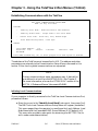
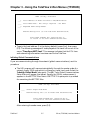
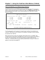
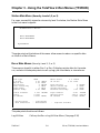
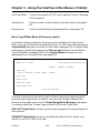
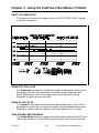
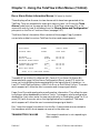
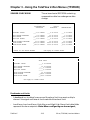
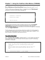
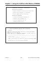
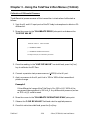
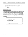
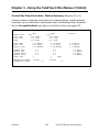
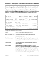
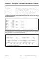

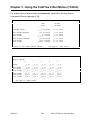
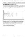
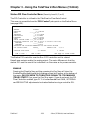
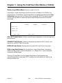
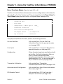

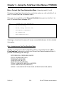

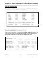
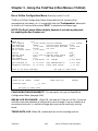
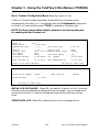
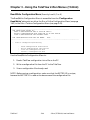
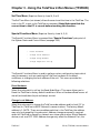
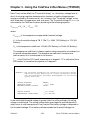
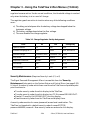
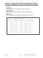
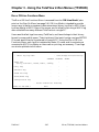

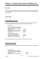
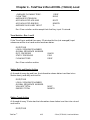
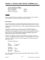
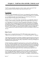


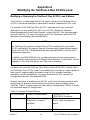
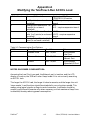


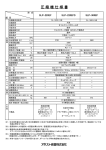


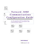


![EnergyAccessOnline User Manual[1]](http://vs1.manualzilla.com/store/data/005906408_1-e15b8e64694c6ea91dc3f2c3109f09fc-150x150.png)