1
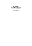
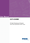
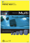
DN-8368MB User Manual (Version 1.0) For Mitsubishi J2 series Servo Driver http://www.icpdas.com DN-8368MB User Manual V 1.0 1 Warranty All products manufactured by ICPDAS Inc. are warranted against defective materials for a period of one year from the date of delivery to the original purchaser. Warning ICPDAS Inc. assumes no liability for damages consequent to the use of this product. ICPDAS Inc. reserves the right to change this manual at any time without notice. The information furnished by ICPDAS Inc. is believed to be accurate and reliable. However, no responsibility is assumed by ICPDAS Inc. for its use, or for any infringements of patents or other rights of third parties resulting from its use. Copyright Copyright 1997-2009 by ICPDAS Inc., LTD. All rights reserved worldwide. Trademark The names used for identification only maybe registered trademarks of their respective companies. License The user can use, modify and backup this software on a single machine. The user may not reproduce, transfer or distribute this software, or any copy, in whole or in part. http://www.icpdas.com DN-8368MB User Manual V 1.0 2 目錄 1 ENGLISH VERSION ......................................................... 4 1.1 Board Layout for DN-8368MB ............................................................................... 4 1.2 I/O Signal connector .............................................................................................. 5 1.3 I/O connector for servo motor of Mitsubishi ..................................................... 11 1.4 Jumper and Switch Settings ............................................................................... 15 1.5 LED Description ................................................................................................... 20 2 繁體中文版 ....................................................................... 21 2.1 DN-8368MB配置 ................................................................................................... 21 2.2訊號連接器 .............................................................................................................. 22 2.3伺服馬達專用訊號連接器 ........................................................................................ 28 2.4 Jumper與 開關調撥設定 ....................................................................................... 32 2.5 LED 功能描述 ........................................................................................................ 37 http://www.icpdas.com DN-8368MB User Manual V 1.0 3 1 English version The DN-8368MB is a terminal board connecting between Mitsubishi J2S series servo driver (with pulse train input amplifier) and ICP DAS PISO-PS600, PISO-VS600 or PMDK motion controller card. Please do not use it to connect any other servo driver or cards. Moreover, it also includes 3-axis I/O signals. We expect to reduce the wiring between Mitsubishi J2S series servo driver and the motion controller card. This manual describes signals and operation instructions of DN-8368MB; the content is divided into 5 parts. 1. Board layout, 2. I/O Signal connectors, 3. Signal connectors for Mitsubishi J2S series servo amplifier, 4. Jumper and switch setting, 5. LED function describes, etc. 1.1 Board Layout for DN-8368MB Dimension and Placement Fig. 1-1 Board layout for the DN-8368MB http://www.icpdas.com DN-8368MB User Manual V 1.0 4 1.2 I/O Signal connector Assuring reliable connections is one of the most important tasks when sending or receiving data from your application systems. This chapter will introduce I/O connector (for general purposes) on DN-8368MB and machine platform specific I/O connector. Users can find various signal usage and meanings in this section. CON1 The I/O connector on DN-8368MB is a 68-pin SCSI II connector that enables you to connect to the sensors and motor drivers to the motion card. Please note: there are two groups of connectors (CN1A/ CN1B) on the main card; therefore, the same signal may have a different name on each sub board. Please refer to Table 1-1, Table 1-2for your reference. http://www.icpdas.com DN-8368MB User Manual V 1.0 5 Table 1-1 CN1A(be close the PCB) No. Name I/O Function Axis 1 AOUT0 O Analog Output No . 35 2 AOUT1 O Analog Output 3 AOUT2 O 4 AGND 5 Name I/O Function Axis AIN0 I Analog Input 36 AIN1 I Analog Input Analog Output 37 AIN2 I Analog Input - Analog Ground 38 AGND - Analog Ground DGND - Digital Ground 39 ERC0 O Error Counter Clear 6 LTC0 I Position Latch 40 SVON0 O Servo On 7 EA0 I Encoder A-Phase 41 RDY0 I Servo Ready 8 EB0 I Encoder B-Phase 42 INP0 I Servo In-Position 9 EZ0 I Encoder Z-Phase 43 ALM0 I Servo Alarm 10 CW0 O 44 SLD0 I Slow Down 11 CCW0 O 45 ORG0 I Origin Signal 12 CMP0 O Clockwise pulse Counter-Clockwise pulse Compare Trigger 46 MEL0 I Minus End Limit 13 EMG I Emergency Stop 47 PEL0 I Positive End Limit 14 ALMRST0 O Servo Alarm Reset 48 DGND - Digital Ground 15 DGND - Digital Ground 49 ERC1 O Error Counter Clear 16 LTC1 I Position Latch 50 SVON1 O Servo On 17 EA1 I Encoder A-Phase 51 RDY1 I Servo Ready 18 EB1 I Encoder B-Phase 52 INP1 I Servo In-Position 19 EZ1 I Encoder Z-Phase 53 ALM1 I Servo Alarm 20 CW1 O 54 SLD1 I Slow Down 21 CCW1 O 55 ORG1 I Origin Signal 22 CMP1 O Clockwise pulse Counter-Clockwise pulse Compare Trigger 56 MEL1 I Minus End Limit 23 GDO1 O Generic Digital Output 57 PEL1 I Positive End Limit 24 ALMRST1 O Servo Alarm Reset 58 DGND - Digital Ground 25 DGND - Digital Ground 59 ERC2 O Error Counter Clear 26 LTC2 I Position Latch 60 SVON2 O Servo On 27 EA2 I Encoder A-Phase 61 RDY2 I Servo Ready 28 EB2 I Encoder B-Phase 62 INP2 I Servo In-Position 29 EZ2 I Encoder Z-Phase 63 ALM2 I Servo Alarm 30 CW2 O 64 SLD2 I Slow Down 31 CCW2 O 65 ORG2 I Origin Signal 32 CMP2 O Clockwise pulse Counter-Clockwise pulse Compare Trigger 66 MEL2 I Minus End Limit 33 DGND - Digital Ground 67 PEL2 I 34 ALMRST2 O Servo Alarm Reset 68 VCC - Positive End Limit 5V Digital Power from Bus http://www.icpdas.com DN-8368MB User Manual V 1.0 6 Table 1-2 CN1B (be distances from PCB) No. Name I/O Function Axis No. Name I/O Function Axis 1 AOUT3 O Analog Output 35 AIN3 I Analog Input 2 AOUT4 O Analog Output 36 AIN4 I Analog Input 3 AOUT5 O Analog Output 37 AIN5 I Analog Input 4 AGND - Analog Ground 38 AGND - Analog Ground 5 DGND - Digital Ground 39 ERC3 O Error Counter Clear 6 LTC3 I Position Latch 40 SVON3 O Servo On 7 EA3 I Encoder A-Phase 41 RDY3 I Servo Ready 8 EB3 I Encoder B-Phase 42 INP3 I Servo In-Position 9 EZ3 I Encoder Z-Phase 43 ALM3 I Servo Alarm 10 CW3 O 44 SLD3 I Slow Down 11 CCW3 O 45 ORG3 I Origin Signal 12 CMP3 O Clockwise pulse Counter-Clockwise pulse Compare Trigger 46 MEL3 I Minus End Limit 13 GDI11 I Generic Digital Input 47 PEL3 I Positive End Limit 14 ALMRST3 O Servo Alarm Reset 48 DGND - Digital Ground 15 DGND - Digital Ground 49 ERC4 O Error Counter Clear 16 LTC4 I Position Latch 50 SVON4 O Servo On 17 EA4 I Encoder A-Phase 51 RDY4 I Servo Ready 18 EB4 I Encoder B-Phase 52 INP4 I Servo In-Position 19 EZ4 I Encoder Z-Phase 53 ALM4 I Servo Alarm 20 CW4 O 54 SLD4 I Slow Down 21 CCW4 O 55 ORG4 I Origin Signal 22 CMP4 O 56 MEL4 I Minus End Limit 23 GDO2 O 57 PEL4 I Positive End Limit 58 DGND - Digital Ground O Error Counter Clear 24 ALMRST4 O Clockwise pulse Counter-Clockwise pulse Compare Trigger Generic Digital Output Servo Alarm Reset 25 DGND - Digital Ground 59 ERC5 26 LTC5 I Position Latch 60 SVON5 O Servo On 27 EA5 I Encoder A-Phase 61 RDY5 I Servo Ready 28 EB5 I Encoder B-Phase 62 INP5 I Servo In-Position 29 EZ5 I Encoder Z-Phase 63 ALM5 I Servo Alarm 30 CW5 O 64 SLD5 I Slow Down 31 CCW5 O 65 ORG5 I Origin Signal 32 CMP5 O Clockwise pulse Counter-Clockwise pulse Compare Trigger 66 MEL5 I Minus End Limit 33 DGND - Digital Ground 67 PEL5 I O Servo Alarm Reset 68 VCC - Positive End Limit 5V Digital Power from Bus 34 ALMRST5 http://www.icpdas.com DN-8368MB User Manual V 1.0 7 CON2 The connectors CON2 are a 5-pin connector for external Power supply (24V input). Table 1-3 shows its I/O connector signal description. Table 1-3 Pin NO 1 2 3 4 5 Pin Define FGND EGND EGND E24V E24V Function description Frame ground of DN-8368MB Ground of the external power Ground of the external power External power supply of +24V DC External power supply of +24V DC CON3 The connector CON3 is a 3-pin connector for connecting general purpose I/O. There are one digital input and one digital output signal, when the connectors connect to the CN1A of main card (the one closer to the PCB board), the input signal is defined as emergency stop. When the connectors connect to the CN1B of main card, the input signal is defined as general purpose input signal. Table 1-4 shows its I/O connector signal description: Table 1-4 Pin NO 1 2 3 Pin Define N.C EMG/GDI11 GDO1/GDO2 http://www.icpdas.com Function description No Connection Emergency stop signal( or General purpose input signal) General purpose output signal DN-8368MB User Manual V 1.0 8 CNAIO (only for PSIO-VS600 and PMDK) This connector is for analog output and input, there are three analog inputs, 3 analog outputs and one analog ground. The user can utilize this to control the analog signal of PISO-VS600 and PMDK, the detail pin-definition is as below (Table 1-5): Table 1-5 Pin NO 1 2 3 4 5 6 7 Pin Define AGND AOUT2 AOUT1 AOUT0 AIN2 AIN1 AIN0 Function description Analog ground Analog output Analog output Analog output Analog input Analog input Analog input CNIO_0 ~ CNIO_2 This connector is used for transmitting general machine signal from each axis, such as, Emergency stop, positive end-limit /negative end-limit, Original (HOME), slow down signals, Latch and Compare signals etc to the main card. The detail pin-definition is as below (Table 1-6): Table 1-6 Pin NO 1 2 3 4 Pin Define CMPCMP+ LTCLTC+ 5 HOME 6 7 8 9 SLD EGND LMTLMT+ 10 EMG 11 E24V Function description Ground for Compare trigger output High Speed Compare trigger output Ground for Position Latch input High Speed Position Latch input Origin signal (ORG) input Slow-Down signal input External Power Ground Negative End Limit signal (MEL) input Positive End Limit signal (PEL) input Emergency stop signal to servo motor driver, direct connect to pin 15 of CN1B External power, direct connect to pin 4 and pin 5 of CON2 http://www.icpdas.com DN-8368MB User Manual V 1.0 9 CN232 This connector is used for communication between Mitsubishi and computer. Because the servo amplifier of Mitsubishi has a RS-232 serial communication function that can be used to perform servo operation, parameter modification, monitor function, etc. User can set up JP8 and JP9, select the desired axis. The detail pin-definition is as below (Table 1-7) Table 1-7 Pin NO 1 2 3 4 5 6 7 8 9 Pin Define N.C TXD RXD N.C AGND N.C N.C N.C N.C Function description No Connection Transmitted data output to RS232 of Personal Computer Received data input from RS232 of Personal Computer No Connection Analog Ground No Connection No Connection No Connection No Connection CNPIO_0 ~ CNPIO_2 This connector usually is used in two ways: first, it can be connected in order to receive external encoder of the linear scale; users can determine to receive encoder source from external linear scale or servo motor by setting JP4 ~ JP6. Another application of CNPIO_0 ~ CNPIO_2 is under the circumstance when not using all Mitsubishi servo motor; stepper or servo motor from manufacturers other than Mitsubishi can be connected together through this connector. The detail pindefinition is as below (Table 1-8): Table 1-8 Pin NO 1 2 3 4 5 6 7 8 9 10 11 12 13 14 15 Pin Define CW+ CCW+ EGND ABEXT_5V CWCCWA+ B+ Z+ ZN.C N.C E24V Function description Positive Direction Pulse(+) Negative Direction Pulse(+) External Power Ground Encoder A-phase(-) Encoder B-phase(-) +5V Power output for external devices Positive Direction Pulse(-) Negative Direction Pulse(-) Encoder A-phase(+) Encoder B-phase(+) Encoder Z-phase(+) Encoder Z-phase(-) No Connection No connection External Power, direct connect to pin 4 and pin 5 of CON2 http://www.icpdas.com DN-8368MB User Manual V 1.0 10 1.3 I/O connector for servo motor of Mitsubishi This chapter describes the signals on terminal board DN-8368MB, which is used to connect the main card with Mitsubishi servo motor. The DN-8368MB supports PISO-PS600 (position control mode), PISO-VS600 (Position/Speed control mode) and PMDK (Professional Motion development Kit, with AI/AO).The Mitsubishi servo motor has various control modes, and different modes may have some common signal or require special setting before operation. Detail explanations for signal pins of CN1A, CN1B, and CN3 on Mitsubishi servo driver will be listed in this section. CN1A_0 ~ CN1A_2 There are 20 pins on CN1A. For these pins are pin-to-pin from motion card to Mitsubishi Server driver, the User can just buy cable and connector to connect them directly. Please note, not all pins are used by ICP DAS’s motion control card. And some of pins may have different function according to different control mode of the servo driver. Table 1-9list the detail definition of pins: Table 1-9 I/O Signals in Servo Drive Pin No. 1 2 3 4 5 6 7 8 9 10 11 12 13 14 15 16 17 18 19 20 Speed control mode Signals in DN-8368MB I/O Position control mode I I NP PP O O O I LZ LA LB CR* LZ LA LB SP1* Z+ A+ B+ Pin 1 of JP15~JP17 PWR SG SG EGND I I NG PG O O O O O PWR LZR LAR LBR INP RD SG CCW+ CW+ CCWCW LZR LAR LBR SA RD SG ZABINP RDY EGND Note: For any pin-define whose symbol is preceded by “*” indicates that by setting Mitsubishi driver parameters (from 43 to 48), it can be set as a different pin-define. http://www.icpdas.com DN-8368MB User Manual V 1.0 11 CN1B_0 ~ CN1B_2 There are 20 pins on CN1B. Since these pins are pin-to-pin from motion card to Mitsubishi Server driver, the User can just buy cable and connector to connect them directly. Please note, not all pins are used by ICP DAS’s motion control card. And some of pins may have different function according to different control mode of servo driver. The detail definitions of pins are as follow: Table 1-10 I/O Signals in Servo Drive I/O Position control mode Speed control mode Signals in DN-8368MB PWR I LG N.C. LG VC AGND AOUT I SON* SON* SRV_ON I PC* ST1* Pin 3 of JP15~JP17 PWR SG SG EGND PWR I COM Reset* EMG COM Reset* EMG I I O LSP LSN ALM LSP LSN ALM E24V ALM_RST SW1 and Pin 10 of CNIO EGND EGND ALARM PWR SG SG EGND Pin No. 1 2 3 4 5 6 7 8 9 10 11 12 13 14 15 I 16 17 18 19 20 Note: For any pin-define whose symbol is preceded by “*” indicates that by setting Mitsubishi driver parameters (from 43 to 48), it can be set as a different pin-define. http://www.icpdas.com DN-8368MB User Manual V 1.0 12 CN3_0 ~ CN3_2 The 3 pins on CN3 of Mitsubishi servo driver work as COM port, allowing the user to read and set configuration from/to servo motor via special software from Mitsubishi. For making things easier, the COM port pins are directed to the CN232 connector of terminal board. By switching JP8~JP9, the users can select which servo motor among these 3 to communicate with. The pins are dentally explained as below: Table 1-11 I/O Signals in Servo Drive Pin No. 1 I/O Position control mode Speed control mode PWR LG LG 2 O TXD TXD 12 I RXD RXD 13 14 15 16 17 18 19 20 PWR O LG MO2 LG MO2 Signals in DN-8368MB AGND Pin 2 of CN232 (selected by JP8) 3 4 5 6 7 8 9 10 11 Pin 3 of CN232 (selected by JP9) AGND AIN Note1: At speed-control mode, MO2 can be used as feedback signal of PISO-VS600, therefore parameter 17 of Mitsubishi driver must be set to 0000 when user use the PISO-VS600 motion card , so that the Servo-motor speed will be output by MO2 (will be connected directly to PISO-VS600analog input). http://www.icpdas.com DN-8368MB User Manual V 1.0 13 Control mode setting DN-8368MB could be used with both PISO-PS600 (position control mode) and PISO-VS600 (Speed control mode), please note that the settings in these two modes are different. The following section describes how to set up parameters for Mitsubishi motor and some notes: z Position Control mode: 1. The parameter 0 (STY) of J2S servo-driver of Mitsubishi must be set to 0000 (Position control mode). 2. Please switch the 4-pin jumper (JP15-JP17) to position1-2, so that the CR signal of J2S servo-driver will be controlled by the ERC signal of PISO-PS600 (or PISO-VS600). z Speed control mode: 1. The parameter 0 (STY) of J2S servo-driver of Mitsubishi must be set to 0002 (Speed control mode). 2. Please switch the 4-pin jumper (JP15-JP17) to position 2-3, so that the ST1 signal of J2S servo-driver will be controlled by the ERC signal of PISO-VS600. Or please switch the jumper to position 3-4, that is: the ST1 signal of J2S servo-driver is connected to GND (Disable the ERC function of PISO-VS600). 3. The parameter 17 (MOD) of J2S servo-driver of Mitsubishi must be set to 0000, so that the output of Servo motor speed will be transmitted via MO2 (It will be directly connected to a PISO-VS 600 analog input.) 4. The parameter 25 (VCM) of J2S servo-driver of Mitsubishi should be set as an appropriate value (the Rotational speed of the motor when Voltage Command is 10V). 5. The parameter 29 (VCD) of J2S servo-driver of Mitsubishi should be set as an appropriate value, so that the motor will be absolute stop when Voltage Command is 0V. Note: When the J2S servo-driver of Mitsubishi is set as speed control mode, I the ST1 signal of J2S servo-driver (CW) (or the ST2 signal of J2S servo-driver (CWW)) must be connected to GND to start the servo motor. The motor speed is depend by the status of SP1~SP3 of J2S servo-driver. If all settings of J2S servo-driver from SP1 to SP3 is turned off, the motor speed will be depend by Voltage command (VC). http://www.icpdas.com DN-8368MB User Manual V 1.0 14 1.4 Jumper and Switch Settings SW1 (EMG SW) The emergency stop signal for each servo amplifier can be selected from SW1. The number 1, 2, 3 on SW1 are denoted as axis 0/3, 1/4, 2/5, respectively. Fig. 1-2 is the default setting for connecting the EMG signals to Pin#2 of JP7 (The default setting is wired to EGND). The EMG signals from CN1B_0 ~ CN1B_2 will not take effect. If the switch is disconnected as shown in Fig. 1-3, the emergency stop signals can be controlled from EMG signals on CNIO_0 ~ CNIO_3. Fig. 1-2 EMG SW setting for normal GND (Default setting) Fig. 1-3 EMG SW setting for user controlled signals. http://www.icpdas.com DN-8368MB User Manual V 1.0 15 JP1 ~ JP3 Jumper 1~3(Fig 1-4) controls the input voltage of LTC for 24V (Jumper position is in 1~2) or 5V (Jumper position is in 2~3). The default setting is 5V. Fig. 1-4 Jumper 1~ Jumper 3 setting JP4 ~ JP6 The encoder signals can be chosen from servo driver encoder or external encoder. Fig. 1-5 shows that the encoder signals are selected from servo driver encoder (default setting). Fig. 1-6 shows that the encoder signals are selected from external encoder. Fig. 1-5 Primary encoder signals setting Fig. 1-6 External encoder signals setting http://www.icpdas.com DN-8368MB User Manual V 1.0 16 JP7 This Jumper is used for setting each axis EMG signal when the SW1 is set to ON, it connects to EGND directly or connects to EMG/GDI11 by user wiring. The detail content is as below (Fig. 1-7 or Fig. 1-8): Fig 1-7 The EMG signal is connected to E_GND, directly. (Default setting) Fig 1-8 the EMG signal is used by EMG/DI11 JP8 ~ JP9 This jumper (JP8 ~ JP9) is used for choosing the RS232 of the computer connect with any axis of DN-8368MB of J2S servo-driver. And they (JP8 and JP9) must be set at the same time. The detail content is as below (Fig. 1-9): Fig 1-9 with what axis link set up RS232 (Default setting is for 0/3-axis) http://www.icpdas.com DN-8368MB User Manual V 1.0 17 JP10 User can choose the analog input source from the connector of CNAIO (from pin5 to pin7) of card (or the MO2 of CN3 of J2s servo-driver via the jumper 10 (JP10). The detail content is as below: Fig 1-10 the analog input of card is connected to the connecter of CNAIO (Pin5 ~ Pin7) (default setting) Fig 1-11 the analog input of card is connected to the MO2 signal of J2S servo-driver http://www.icpdas.com DN-8368MB User Manual V 1.0 18 JP15 ~ JP17 This Jumper (JP15~JP17) can be used for choosing the ERC signal of card use way with position control or speed control. Please refer to the section (Control Mode Setting), before. Fig 1-12 The ERC signal of main card controls the J2S’s CR signal. (Default setting) Fig 1-13 The ERC signal of main card controls the J2S’s signal. Fig 1-14 The ST1 signal of J2S connects to EGND, directly. http://www.icpdas.com DN-8368MB User Manual V 1.0 19 1.5 LED Description LED is used for indicating a specific or emergent DI state, there are two types of LED indicator on the daughter board, one is for showing machine I/O state (Home, LMT-, LMT+, RDY, etc.), the other is for showing Power and EMG state. The detail descriptions are as follows: z HOME: It shows the original signal of motion control on the machine. The LED will be turned on when the motion control is moved to the original signal. z LMT -: It shows the minus end-limit signal of motion control on the machine. The minus end-limit signal of motion axis is to decide the end point of minus moving. If this signal is on, the LED will be turned on. (This is the case when "Normal Open" mode is set, for "Normal Close" mode, the LED is turned off when signal is on.) z LMT +: It shows the plus end-limit signal of motion control on the machine. The plus end-limit signal of motion axis is to decide the end point of plus moving. If this signal is on, the LED will be turned on. (This is the case when "Normal Open" mode is set, for "Normal Close" mode, the LED is turned off when signal is on.) z RDY: It point out whether the servo motor is in the state ready for operation. The LED will be turned on when the motor is ready z Power: It shows the power state of DN-8368GB. The LED will be turned on when the power is inputted. z EMG: It shows the state of EMG signal. The LED will be turned on when the EMG signal is triggered http://www.icpdas.com DN-8368MB User Manual V 1.0 20 2 繁體中文版 DN-8368MB 是泓格科技股份有限公司專為三菱伺服馬達動器 J2 系列,所設計的三軸專用配接端 子台。此產品可搭配泓格科技公司所設計的PISO-PS600 , PISO-VS600 及 PMDK 等運動控制產 品(本文之後統稱為主卡)。我們期望客戶經由此專用端子板減少控制卡與三菱伺服馬達之間的配 線及降低配線的錯誤, 提高客戶的競爭能力。本手冊主要是描述此端子板上的所有訊號及相關使 用手說明,內容共分為:1. 端子板配置、 2. 訊號連接器、 3. 伺服馬達訊號專用連接器、4. Jumper 與開關調撥設定、 5. LED 功能描述等五大部份。 2.1 DN-8368MB配置 尺寸與配置 Fig. 2-1 Board layout for the DN-8368MB http://www.icpdas.com DN-8368MB User Manual V 1.0 21 2.2訊號連接器 保持信號連接是在保證使用者的應用系統能正確地送出和得到數據過程中最重要的元素。所以本 節主要就是介紹端子板上的一般用途之I/O 端子接頭、機台使用 I/O 端子接頭及伺服馬達專用連接 器的各訊號配接點意義說明。除了讓使用者可以了解訊號用途及意義外,更可以讓使用者依此再 確認訊號配接是否正確。 CON1 DN-8368 MB 上的 I/O 連接器是經由 68 腳位的 SCSI II 的連接器端子,讓使用者可以將端子 板訊號連接到主控端的主卡。由於主卡上有兩組連接器(CN1A/ CN1B),因此對應到端子板 上的訊號名稱時將有有所不同,故我們將相關的訊號表列於下【表2-1 、表 2-2 】;不過因為此連 接器僅是將端子台與主卡的控制訊號直接連接起來,而使用者並無法直接控制使用,所以使用者 是可以忽略此說明內容! http://www.icpdas.com DN-8368MB User Manual V 1.0 22 CN1A(較靠近PCB板)表2-1 No. Name I/O Function Axis 1 AOUT0 O Analog Output No . 35 2 AOUT1 O Analog Output 3 AOUT2 O 4 AGND 5 Name I/O Function Axis AIN0 I Analog Input 36 AIN1 I Analog Input Analog Output 37 AIN2 I Analog Input - Analog Ground 38 AGND - Analog Ground DGND - Digital Ground 39 ERC0 O Error Counter Clear 6 LTC0 I Position Latch 40 SVON0 O Servo On 7 EA0 I Encoder A-Phase 41 RDY0 I Servo Ready 8 EB0 I Encoder B-Phase 42 INP0 I Servo In-Position 9 EZ0 I Encoder Z-Phase 43 ALM0 I Servo Alarm 10 CW0 O 44 SLD0 I Slow Down 11 CCW0 O 45 ORG0 I Origin Signal 12 CMP0 O Clockwise pulse Counter-Clockwise pulse Compare Trigger 46 MEL0 I Minus End Limit 13 EMG I Emergency Stop 47 PEL0 I Positive End Limit 14 ALMRST0 O Servo Alarm Reset 48 DGND - Digital Ground 15 DGND - Digital Ground 49 ERC1 O Error Counter Clear 16 LTC1 I Position Latch 50 SVON1 O Servo On 17 EA1 I Encoder A-Phase 51 RDY1 I Servo Ready 18 EB1 I Encoder B-Phase 52 INP1 I Servo In-Position 19 EZ1 I Encoder Z-Phase 53 ALM1 I Servo Alarm 20 CW1 O 54 SLD1 I Slow Down 21 CCW1 O 55 ORG1 I Origin Signal 22 CMP1 O Clockwise pulse Counter-Clockwise pulse Compare Trigger 56 MEL1 I Minus End Limit 23 GDO1 O Generic Digital Output 57 PEL1 I Positive End Limit 24 ALMRST1 O Servo Alarm Reset 58 DGND - Digital Ground 25 DGND - Digital Ground 59 ERC2 O Error Counter Clear 26 LTC2 I Position Latch 60 SVON2 O Servo On 27 EA2 I Encoder A-Phase 61 RDY2 I Servo Ready 28 EB2 I Encoder B-Phase 62 INP2 I Servo In-Position 29 EZ2 I Encoder Z-Phase 63 ALM2 I Servo Alarm 30 CW2 O 64 SLD2 I Slow Down 31 CCW2 O 65 ORG2 I Origin Signal 32 CMP2 O Clockwise pulse Counter-Clockwise pulse Compare Trigger 66 MEL2 I Minus End Limit 33 DGND - Digital Ground 67 PEL2 I 34 ALMRST2 O Servo Alarm Reset 68 VCC - Positive End Limit 5V Digital Power from Bus http://www.icpdas.com DN-8368MB User Manual V 1.0 23 CN1B(較遠離PCB板)表2-2 No. Name I/O Function Axis No. Name I/O Function Axis 1 AOUT3 O Analog Output 35 AIN3 I Analog Input 2 AOUT4 O Analog Output 36 AIN4 I Analog Input 3 AOUT5 O Analog Output 37 AIN5 I Analog Input 4 AGND - Analog Ground 38 AGND - Analog Ground 5 DGND - Digital Ground 39 ERC3 O Error Counter Clear 6 LTC3 I Position Latch 40 SVON3 O Servo On 7 EA3 I Encoder A-Phase 41 RDY3 I Servo Ready 8 EB3 I Encoder B-Phase 42 INP3 I Servo In-Position 9 EZ3 I Encoder Z-Phase 43 ALM3 I Servo Alarm 10 CW3 O 44 SLD3 I Slow Down 11 CCW3 O 45 ORG3 I Origin Signal 12 CMP3 O Clockwise pulse Counter-Clockwise pulse Compare Trigger 46 MEL3 I Minus End Limit 13 GDI11 I Generic Digital Input 47 PEL3 I Positive End Limit 14 ALMRST3 O Servo Alarm Reset 48 DGND - Digital Ground 15 DGND - Digital Ground 49 ERC4 O Error Counter Clear 16 LTC4 I Position Latch 50 SVON4 O Servo On 17 EA4 I Encoder A-Phase 51 RDY4 I Servo Ready 18 EB4 I Encoder B-Phase 52 INP4 I Servo In-Position 19 EZ4 I Encoder Z-Phase 53 ALM4 I Servo Alarm 20 CW4 O 54 SLD4 I Slow Down 21 CCW4 O 55 ORG4 I Origin Signal 22 CMP4 O 56 MEL4 I Minus End Limit 23 GDO2 O 57 PEL4 I Positive End Limit 58 DGND - Digital Ground O Error Counter Clear 24 ALMRST4 O Clockwise pulse Counter-Clockwise pulse Compare Trigger Generic Digital Output Servo Alarm Reset 25 DGND - Digital Ground 59 ERC5 26 LTC5 I Position Latch 60 SVON5 O Servo On 27 EA5 I Encoder A-Phase 61 RDY5 I Servo Ready 28 EB5 I Encoder B-Phase 62 INP5 I Servo In-Position 29 EZ5 I Encoder Z-Phase 63 ALM5 I Servo Alarm 30 CW5 O 64 SLD5 I Slow Down 31 CCW5 O 65 ORG5 I Origin Signal 32 CMP5 O Clockwise pulse Counter-Clockwise pulse Compare Trigger 66 MEL5 I Minus End Limit 33 DGND - Digital Ground 67 PEL5 I O Servo Alarm Reset 68 VCC - Positive End Limit 5V Digital Power from Bus 34 ALMRST5 http://www.icpdas.com DN-8368MB User Manual V 1.0 24 CON2 此控制接點為此端子板的電源入力接點,共有 5 腳位 , 詳細腳位描述內容如表 2-3 : 表 2-3 Pin NO 1 2 3 4 5 Pin Define FGND EGND EGND E24V E24V Function description Frame ground of DN-8368MB Ground of the external power Ground of the external power External power supply of +24V DC External power supply of +24V DC CON3 一般用途的 I/O 配接點, DI 及 DO 各 1 , 其中 DI 的部份, 當接到主卡的 CN1A(較靠近 PCB 板)時 , 此訊號為緊急停止( EMG )開關之輸入; 當接到主卡的 CN1B(較遠離 PCB 板)時, 做為一般 用途的GDI11 使用 , 詳細腳位描述內容如表 2-4 : 表 2-4 Pin NO 1 2 3 Pin Define N.C EMG/GDI11 GDO1/GDO2 Function description No Connection Emergency stop signal( or General purpose input signal) General purpose output signal CNAIO (only for PSIO-VS600 and PMDK) 此為類比輸出入訊號配接點, 共計有 AI x3, AO x3 及 analog ground x1 ,使用者可以利用此來 將PISO-VS600 and PMDK 的類比控制訊號輸出 , 詳細腳位描述內容如表 2-5 : 表 2-5 Pin NO 1 2 3 4 Pin Define AGND AOUT2 AOUT1 AOUT0 Function description Analog ground Analog output Analog output Analog output 5 AIN2 Analog input 6 AIN1 Analog input 7 AIN0 Analog input http://www.icpdas.com DN-8368MB User Manual V 1.0 25 CNIO_0 ~ CNIO_2 此配接口主要是讓使用者可以配接各軸的一般機台 I/O 訊號, 例如 : 緊急訊號、 正負極限 , 歸零、 減速訊號、 LTC 、 正負 CMP 等, 透過這些配接點可以讓使用者輕易的將這些機台常用的訊號引 入控制卡, 達到控制。 詳細腳位描述內容如表 2-6 : 表 2-6 Pin NO 1 2 3 4 Pin Define CMPCMP+ LTCLTC+ 5 HOME 6 SLD 7 8 9 EGND LMTLMT+ 10 EMG 11 E24V Function description Ground for Compare trigger output High Speed Compare trigger output Ground for Position Latch input High Speed Position Latch input Origin signal (ORG) input Slow-Down signal input External Power Ground Negative End Limit signal (MEL) input Positive End Limit signal (PEL) input Emergency stop signal to servo motor driver, direct connect to pin 15 of CN1B External power, direct connect to pin 4 and pin 5 of CON2 CN232 主要提供使用者可以將電腦上的 COM Port 與三菱伺服馬達驅動器上的 CN3 中的 RS-232 通訊串 口連接使用, 再經由設定 JP8~JP9 來選定接到此端子板上的 3 軸中欲讀取的伺服馬達驅動器內 容;經由此貼心設定可省去客戶常因為須要調機或者設定驅動器之內定值而一直插拔線材;詳細 的腳位內容描述如表2-7: 表 2-7 Pin NO 1 2 3 4 5 6 7 8 9 Pin Define N.C TXD RXD N.C AGND N.C N.C N.C N.C Function description No Connection Transmitted data output to RS232 of Personal Computer Received data input from RS232 of Personal Computer No Connection Analog Ground No Connection No Connection No Connection No Connection http://www.icpdas.com DN-8368MB User Manual V 1.0 26 CNPIO_0 ~ CNPIO_2 此配接口主要有兩大用途, 第一提供使用者可以配接外部光學尺訊號的輸入點, 再搭配 Jumper 之 JP4~JP6 的設定選擇 Encoder 訊號來源是由伺服馬達 (CN1A) 或者是外部光學尺; 第二為當使 用者的應用上, 並非全數為三菱伺服馬達時, 而是有一軸 ( 或兩軸 ) 是步進 ( 或他牌伺服 ) 馬達時, 可以經由此配接口來配接結合使用,可以讓使用者做多變化的配接, 詳細的腳位內容描述如表 2-8: 表 2-8 Pin NO 1 2 3 4 5 6 7 8 9 10 11 12 13 14 15 Pin Define CW+ CCW+ EGND ABEXT_5V CWCCWA+ B+ Z+ ZN.C N.C E24V Function description Positive Direction Pulse(+) Negative Direction Pulse(+) External Power Ground Encoder A-phase(-) Encoder B-phase(-) +5V Power output for external devices Positive Direction Pulse(-) Negative Direction Pulse(-) Encoder A-phase(+) Encoder B-phase(+) Encoder Z-phase(+) Encoder Z-phase(-) No Connection No connection External Power, direct connect to pin 4 and pin 5 of CON2 http://www.icpdas.com DN-8368MB User Manual V 1.0 27 2.3伺服馬達專用訊號連接器 本章節主要是說明三菱伺服馬達在 DN-8368MB 上的端子接點訊號說明, 由於此端子板是可配 PISO-PS600 (position control mode) , PISO-VS600 (Position/Speed control mode) 及 PMDK (Professional Motion development Kit ( 支援 AI/AO)) 多卡共用端子板; 再加上三菱的 伺服馬達又可以經由設定而有不同的控制模式,而這些不同的控制模式中又有些訊號腳位是共用 或者是須要經由設定驅動器後始可操作, 所以我們特別將這些三菱伺服驅動器上的 CN1A 、 CN1B 、 CN3 等的控制腳位的定義特別列出來說明,讓使用者可以經由這的說明而能容易的操控 不同模式的馬達模式控制。 CN1A_0 ~ CN1A_2 軸卡與三菱伺服驅動器 CN1A 連接之配腳口 , 此配接口共有 20Pin , 為直接腳位對應引入, 使用 者可以直接將購買的三菱線材與端子板的連接頭對接即可。泓格科技股份公司之運動控制卡並未 全數引用所有三菱伺服的腳位,我們僅僅使用部份腳位, 且由於各腳位於伺服馬達驅動器的控制 模式設定改變時,部份腳位定義也將會依控制模式的改變而有所改變, 詳細定義內容如表 2-9 : 表 2-9 I/O Signals in Servo Drive Pin No. 1 2 3 4 5 6 7 8 9 10 11 12 13 14 15 16 17 18 19 20 Speed control mode Signals in DN-8368MB I/O Position control mode I I NP PP O O O I LZ LA LB CR* LZ LA LB SP1* Z+ A+ B+ Pin 1 of JP15~JP17 PWR SG SG EGND I I NG PG O O O O O PWR LZR LAR LBR INP RD SG CCW+ CW+ CCWCW LZR LAR LBR SA RD SG ZABINP RDY EGND 註:有打 * 號的腳位是代表該訊號可以經由三菱伺服馬達驅動器 (J2S) 的 Para.43~48 的設定來改 變腳位定義名稱。 http://www.icpdas.com DN-8368MB User Manual V 1.0 28 CN1B_0 ~ CN1B_2 軸卡與三菱伺服驅動器 CN1B 連接之配腳口 , 此配接口共有 20Pin , 為直接腳位對應引入, 使用 者可以直接將購買的三菱線材與端子板的連接頭對接即可。 泓格之運動控制卡並未全數引用所有 三菱伺服的腳位, 我們僅僅使用部份腳位, 且由於各腳位於伺服馬達驅動器的控制模式設定改 變時,部份腳位定義也將會依控制模式的改變而有所改變, 詳細定義內容如表 2-10 : 表 2-10 I/O Signals in Servo Drive I/O Position control mode Speed control mode Signals in DN-8368MB PWR I LG N.C. LG VC AGND AOUT I SON* SON* SRV_ON I PC* ST1* Pin 3 of JP15~JP17 PWR SG SG EGND PWR I COM Reset* EMG COM Reset* EMG I I O LSP LSN ALM LSP LSN ALM E24V ALM_RST SW1 and Pin 10 of CNIO EGND EGND ALARM PWR SG SG EGND Pin No. 1 2 3 4 5 6 7 8 9 10 11 12 13 14 15 I 16 17 18 19 20 註 : 有打 * 號的腳位是代表該訊號可以經由三菱伺服馬達驅動器 (J2S) 的 Para.43~48 的設定來改變 腳位定義名稱。 http://www.icpdas.com DN-8368MB User Manual V 1.0 29 CN3_0 ~ CN3_2 三菱伺服馬達驅動器之的 CN3 的腳位中有 3Pin 是用來當成 COM port 使用 , 而其主要的用途是讓 使用者利用三菱伺服馬達專用的軟體,如Melservo-161 經由電腦透過 COM Port 來讀取驅動器, 主要為設定驅動器及調機等使用 . 因此 , 為了方便使用者使用故我們將此功能直接引入到端子板 上, 使用者可以利用我們的 CN232 接口直接連接電腦的 COM Port ,再經由端子板上的 JP8~JP9 來選擇接到此端子板上的 3 軸中欲讀取的伺服馬達驅動器內容; 詳細的腳位內容描述如 表2-11 : 表 2-11 I/O Signals in Servo Drive Pin No. 1 I/O Position control mode Speed control mode PWR LG LG 2 O TXD TXD 12 I RXD RXD 13 14 15 16 17 18 19 20 PWR O LG MO2 LG MO2 Signals in DN-8368MB AGND Pin 2 of CN232 (selected by JP8) 3 4 5 6 7 8 9 10 11 Pin 3 of CN232 (selected by JP9) AGND AIN 註 1 : MO2 在 Speed control mode 可被當做 PISO-VS600 的參考回授值,因此當使用者若是搭 配PISO-VS600 使用此端子板時 , 須將伺服馬達的參數 17 之值設定為 0000 ,將Servo motor speed 經由 MO2 輸出 ( 會直接接到 PISO-VS600 的 analog input) 。 http://www.icpdas.com DN-8368MB User Manual V 1.0 30 控制模式設定 (Control mode setting) 由於 DN-8368MB 是可以跟PISO-PS600 (position control mode) and PISO-VS600 (Speed control mode) 兩種控制卡搭配 , 故我們特別將此兩種模式的特別要調之參數及注意事項來列出 並提醒使用者,以避免不必要的錯誤產生: z Position Control mode: 1. 將伺服馬達驅動器上的 Parameter 0 (STY) 之值設定為 : 0000 (Position control) 。 2. 將 JP15~JP17 之 4-Pin Jumper 放在 1-2 位置 ( 由 PISO-PS600/PISO-VS600 之 ERC 來 控制伺服馬達的CR訊號。 z Speed control mode: 1. J2S 的 parameter 0 (STY) 要設成 0002 (speed control) 2. 4 pin jumper (JP15-JP17) 放在 2-3 的位置 ( 由 VS600 的 ERC 控制 J2S 的 ST1) 或 是放在 3-4 的位置 (J2S 的 ST1 直接接地 , VS600 的 ERC 不使用 ) 3. J2S 的 parameter 17 (MOD) 要設成 0000 , 將 Servo motor speed 經由 MO2 輸出 ( 會接到 VS600 的 analog input) 4. 將 J2S 的 parameter 25 (VCM) 設定成適當的值 (Voltage Command 為 10V 時馬達 的轉速) 5. 將 J2S 的 parameter 29 (VCO) 設定成適當的值 , 使 Voltage Command 為 0V 時馬 達完全靜止 註: 當 J2S 設定在 Speed control mode 時, 一定要將 ST1 ( 代表正轉 ) 或 ST2 ( 代表反轉 ) 其中一 pin 接地馬達才會轉動,而馬達轉動的速度 , 則是依據 SP1~SP3 的狀態決定 , ,當 SP1~SP3 都是 off 時, 馬達的轉速由 Voltage Command - VC 決定。 http://www.icpdas.com DN-8368MB User Manual V 1.0 31 2.4 Jumper 與 開關調撥設定 SW1 (EMG SW) 三菱的伺服馬達驅動器有一控制訊號是用來讓伺服馬達在緊急的情形下可以執行緊急停止, 而此 訊號是一不必經由控制卡即可以讓馬達停止的重要訊號, 故我們在設計端子板時也考慮到客戶使 用上的須求, 而特別將每軸的此訊號連接到端子板的 SW1 開關, 供給客戶可以直接由硬體來設 定為直接接到端子板的GND ( 此為出廠預設值 ) , 還是使用者接到外部的感應開關來當觸發點。 而 SW1 共有 4 組的訊號點 , 其中 1 ~ 3 分別就是被用來設定端子板的 0/3 ~ 2/5 等三軸的緊急停止訊 號的使用方式。 Fig. 2-2 是顯示 SW1 出廠預設值 ( 被直接接到 EGND) , 因此端子板上的 CN1B_0 ~ CN1B_2 的 ENG (Pin#2) 是無效; Fig. 2-3 是顯示 SW1 調撥設定為可以讓使用者經 由端子板上的CNIO_0 ~ CNIO_2 的 EMG 腳位與外部的感應開關結合使用。 Fig. 2-2 EMG SW setting for normally GND (Default setting) Fig. 2-3 EMG SW setting for user controlled signals. http://www.icpdas.com DN-8368MB User Manual V 1.0 32 JP1 ~ JP3 Jumper 1~3 主要是用來設定 LTC 訊號的輸入電壓為是 24V (Jumper 位置在 1~2) 或 5V (Jumper 位置在 2~3) 。 而此訊號的出廠預設值為 5V 。 Fig. 2-4 Jumper 1~ Jumper 3 setting JP4 ~ JP6 JP4 ~ JP6 主要是用來設定編碼器的訊號來源,可選擇直接從伺服馬達或由外部編碼器 ( 光學尺 ) 當輸入源 Fig. 2-5 顯示設定訊號源是伺服馬達 ( 此為出廠預設值 ) 。 Fig. 2-6 顯示設定訊號源為外 部的編碼器。 Fig. 2-5 Primary encoder signals setting Fig. 2-6 External encoder signals setting http://www.icpdas.com DN-8368MB User Manual V 1.0 33 JP7 此 Jumper 主要是用來設定當 SW1 被切到 ON 時, , 各軸的 EMG 訊號是直接接到 EGND 或者是由 EMG/GDI11 來搭配外部配接點使用 , 其設定內容詳如下圖所示: Fig 2- 7 各軸的 EMG 訊號直接接到 E_GND ( 出廠預設值 ) Fig. 2-8 各軸的 EMG 訊號由 EMG/GDI11 來配接使用 http://www.icpdas.com DN-8368MB User Manual V 1.0 34 JP8 ~ JP9 此組 Jumper( JP8~JP9) 主要是用來提供使用者可以選擇電腦連接過來的 RS-232 與端子板上的那 一組三菱伺馬達驅動器連結, 而且每次的調整必須是 JP8 與 JP9 一起且一致的調整。 其設定內容 詳如下圖所示: Fig. 2-9 用來設定 RS232 與何軸連結 ( 出廠預設值為第 0/3 軸 ) JP10 此組 Jumper( JP10) 主要是用來提供使用者可以選擇主卡的 analog input 是要連接到 CNAIO 的 Pin#5~Pin#7 或是 J2S 的 MO2 訊號 ( 位於 CN3 上 ). 其設定內容詳如下圖所示: Fig. 2-10 主卡的 analog input 是連接到 CNAIO 的 Pin#5~Pin#7 ( 出廠設值 ) Fig. 2-11 主卡的 analog input 是連接 J2S 的 MO2 訊號 http://www.icpdas.com DN-8368MB User Manual V 1.0 35 JP15 ~ JP17 此組 Jumper( JP15~JP17) 主要是用來提供使用者配合其所使用的控制模式(Position Control/Speed control) 來選擇主卡上的 ERC 訊號使用方法。 詳細使用方法請參考“Control Mode Setting” 章節。 Fig. 2-12 主卡的 ERC 訊號控制 J2S 的 CR 訊號 ( 出廠預設值 ) Fig. 2-13 主卡的 ERC 訊號控制 J2S 的 ST1 訊號 Fig. 2-14J2S 的 ST1 訊號直接接到 EGND http://www.icpdas.com DN-8368MB User Manual V 1.0 36 2.5 LED 功能描述 LED 主要是用來顯示特別或重要的 DI 狀態 , 此端子板上大致分成為兩部份, 一個為各軸的機台機 械I/O ( 依序為 : HOME, LMT- LMT- and RDY) 狀態顯示; 另一為 Power LED and EMG LED 狀 態顯示; 這些 LED 的主要意義詳如下述: z HOME : 運動控制軸的歸原點訊號。 當訊號被觸發作動時 LED 將會被點亮! z LMT - : 運動控制軸的負極限訊號 , 主要是用來決定硬體的負向運動的最大點 ; 當此 訊號被觸發作動時, LED 點將會被點亮 ( 由於實體電路為 NO [Normal Open] , 所以 當使用者的開關為Normal Close 的設計時,則 LED 的顯示會剛好與前述相反 ) ! z LMT + : 運動控制軸的正極限訊號, 主要是用來決定硬體的正向運動的最大點 ; 當 此訊號被觸發作動時, LED 點將會被點亮 ( 由於實體電路為 NO [Normal Open] , 所以當使用者的開關為 Normal Close 的設計時,則 LED 的顯示會剛好與前述相反 ) ! z RDY : 指示伺服馬達是否處於可以被控制的狀態 ; 當 LED 被點亮時即代表伺服馬達 是處在可被控制的狀態。 z Power : 當端子板的電源入力端被正確的接入所要求電源後, Power LED 將會被點 亮. z EMG : 主要是顯示 EMG 訊號是否被啟觸發做動,當被觸發作動則會點亮 LED 。 http://www.icpdas.com DN-8368MB User Manual V 1.0 37


![一括版[PDF1,136KB]](http://vs1.manualzilla.com/store/data/006595740_2-45b661bdf64a7a1a2486bf0cd725059f-150x150.png)