1
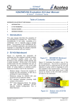
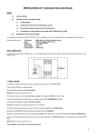
EV8600
CML Microcircuits
Modem
Evaluation Kit
COMMUNICATION SEMICONDUCTORS
UM8600/2 February 2006
Provisional Issue
Features
•
For the evaluation of the CMX865 and
CMX868A modems
•
Test points for convenient access
to most useful signals
•
Target IC Socket for ease of use
•
On-board 11.0592MHz Xtal circuit
•
Connectors for convenient connection of
external DAA, host micro cards and testmeasurement equipments
•
On-board 3.3V voltage regulator
supplies both analogue and digital
rails
•
Operation with users host controller card
or CML PE0001 Interface Card
•
Powered by a single, +5V
unregulated supply
1
Brief Description
The EV8600 forms a basic evaluation platform for the CMX865 and CMX868A wireline modems. The
board is populated with a dual-in-line socket to host the desired target IC and other components that are
common to the two modems.
Two on-board connectors are provided for signal interfacing. The modem connector provides the
analogue signal inputs and outputs plus other relevant signals to allow the addition of custom DAAs or to
facilitate the connection of telecom test-measurment equipment. The C-BUS connector breaks out the full
C-BUS serial interface for convenient connection of a host processor card or the CML PE0001 Evaluation
Kit Interface Card.
Continued….
© 2006 CML Microsystems Plc
EV8600 Evaluation Kit
EV8600
An on-board 3.3 volt filtered and regulated circuit is distributed to analogue and digital rails and is also
available at both the modem connector and C-Bus connector for powering off-board circuits.
IC timing is made available by an on-board 11.0592MHz Xtal clock. On-board test-points provide easy
access to IRQ and chip select functions as well as both analogue and digital ground points.
The analogue and digital ground planes are physically seperate but electrically coupled with a zero-Ohm
resistor. This resistor can be removed or replaced with a capacitor if required.
Evaluation ICs are not supplied with this EvKit and should be purchased separately.
© 2006 CML Microsystems Plc
2
UM8600/2
EV8600 Evaluation Kit
EV8600
CONTENTS
Page
Section
1
Brief Description ..................................................................................... 1
2.
Preliminary Information.......................................................................... 4
2.1
Laboratory Equipment............................................................... 4
2.2
Handling Precautions ................................................................ 4
2.3
Approvals.................................................................................... 4
3.
Quick Start ............................................................................................... 5
4.
Signal Lists .............................................................................................. 6
5.
Circuit Schematics and Board Layouts................................................ 8
6.
Detailed Description ............................................................................... 9
6.1
Hardware Description................................................................ 9
6.2
Adjustments and Controls ........................................................ 9
7.
Performance Specification................................................................... 10
7.1
Electrical Performance ............................................................ 10
It is always recommended that you check for the latest product datasheet version from the
Datasheets page of the CML website: [www.cmlmicro.com].
© 2006 CML Microsystems Plc
3
UM8600/2
EV8600 Evaluation Kit
2.
Preliminary Information
2.1
Laboratory Equipment
EV8600
The following laboratory equipment is needed to use this evaluation kit:
2.1.1
Power Supply
+5V (nominal), 300mA
2.2
Handling Precautions
Like most evaluation kits, this product is designed for use in laboratory environments. The
following practices will help ensure its proper operation.
2.2.1
Static Protection
This product uses low power CMOS circuits which can be damaged by electrostatic discharge.
Partially damaged circuits can function erroneously, leading to misleading results. Observe ESD
precautions at all times when handling this product.
2.2.2
Contents - Unpacking
Please ensure that you have received all of the items on the separate information sheet (EK8600)
and notify CML within 7 working days if the delivery is incomplete.
2.3
Approvals
There are no approvals for this product.
© 2006 CML Microsystems Plc
4
UM8600/2
EV8600 Evaluation Kit
3.
EV8600
Quick Start
Firstly, a sample of the chosen target device, not supplied, CMX865P4 or CMX868AP4, must be
fitted to the socket provided, U1.
An example of how the EV8600 evaluation board may be used in a modem development system
is shown below:
Header
Signals
J2
EV8600
LINE
Customer's
Interface cct
or DAA
Customer's
Host
Processor
J1
C-BUS
Emulator
Simulator or
Test
Equipment
J3
Modem or
Line
Connection
CMX865P4
Device
Options
Power Supply
4.5 -> 9 volts dc
CMX868AP4
Figure 1 Modem development using EV8600
Care should be taken when connecting the EV8600 to external circuits, as the C-BUS
connector (J1) and the line connector (J2) are of the same form factor.
© 2006 CML Microsystems Plc
5
UM8600/2
EV8600 Evaluation Kit
EV8600
4.
Signal Lists
CONNECTOR PINOUT
Connector
Ref.
Connector
Pin No.
Signal
Name
Signal
Type
J1
1
-
N/C
2
CSN
I/P
3
-
N/C
4
CDATA
I/P
5
-
N/C
6
SCLK
I/P
7
-
N/C
8
RDATA
O/P
9
-
N/C
10
IRQN
O/P
11, 12
GNDD
PWR
13, 14, 15,
16, 17, 18
-
N/C
19, 20
VDDD
PWR
1
-
N/C
2
RLYDRV
O/P
3
-
N/C
4
RD
I/P
5
VDDD
PWR
6
RT
BI
7, 8
GNDD
PWR
Digital supply ground.
9, 10
GNDA
PWR
Analogue supply ground.
11
RXAFB
O/P
Receive amplifier feedback.
12
RXAN
I/P
Receive amplifier inverting input.
13
RXA
I/P
Receive amplifier non-inverting input.
14
VBIAS
BI
Analogue bias voltage, 1.65V dc.
15, 16
GNDA
PWR
J2
© 2006 CML Microsystems Plc
6
Description
C-BUS Chip select. Connects to host µC.
C-BUS Serial data input. Connects to host
µC.
C-BUS Serial clock input. Connects to host
µC.
C-BUS Serial data output. Connects to
host µC.
C-BUS Interrupt request. Connects to host
µC.
Digital supply ground.
3.3V dc digital supply rail.
Hook switch control.
Ring detector input.
3.3V dc digital supply rail.
Ring detector time constant.
Analogue supply ground.
UM8600/2
EV8600 Evaluation Kit
EV8600
CONNECTOR PINOUT
Connector
Ref.
Connector
Pin No.
Signal
Name
Signal
Type
J2
17
TXAN
O/P
Transmit negative output.
18
TXA
O/P
Transmit positive output.
19
-
N/C
20
VDDA
PWR
3.3V dc analogue supply rail.
1
+VIN
PWR
External supply voltage.
2
GNDA
PWR
External supply ground.
J3
Description
TEST POINTS
Test Point
Ref.
Default
Measurement
TP1
0V
Digital supply ground.
TP2
0V
Digital supply ground.
TP3
0V
Analogue supply ground.
TP4
0V
Analogue supply ground.
TP5
+3.3V
C-BUS Interrupt output.
TP6
+3.3V
C-BUS Chip Select input.
Notes: I/P
O/P
BI
N/C
PWR
© 2006 CML Microsystems Plc
=
=
=
=
=
Description
Input
Output
Bidirectional
Not connected
Power supply connection
7
UM8600/2
EV8600 Evaluation Kit
5.
EV8600
Circuit Schematics and Board Layouts
For clarity, circuit schematics are available as separate high resolution files. This can be found on
the CML website.
X1
Board Mod
1 2 3 4
U1
EV8600
C4
C6
J2
TP5
R3
C5
J1
TP1
TP6
C3
L1
C2
+
+
C7
U2
TP2
52.7mm
R4
0v J3 + 5v
TP3
+
C1
TP4
R2
C8
R1
Figure 2 Evaluation Board - Layout
© 2006 CML Microsystems Plc
8
UM8600/2
EV8600 Evaluation Kit
6.
Detailed Description
6.1
Hardware Description
6.1.1
Power supply
EV8600
The board is fitted with a voltage regulator, U2. The voltage is set to +3.3V dc. Analogue and
digital supplies are separated by an inductor, L1. The analogue and digital ground planes are
separated by a 0Ω link, R4. There is available current capacity in the regulator to power external
circuitry on both the modem and control sides of the board.
6.1.2
Clock/Oscillator
The CMX86x target device is clocked at a frequency of 11.0592MHz, which is provided by crystal
X1.
6.1.3
Modem Interface
All analogue signals, hook switch control and ring detector input are brought to this connector, J2.
In addition both analogue and digital supplies are available for powering external circuitry.
6.1.4
C-BUS interface
The C-BUS control signals and the C-BUS interrupt request signal are brought to this connector,
J1. In addition the digital supply is available for powering external circuitry. This connector is pin
compatible with the CML PE0001 evaluation kit interface card.
6.2
Adjustments and Controls
None
© 2006 CML Microsystems Plc
9
UM8600/2
EV8600 Evaluation Kit
7.
Performance Specification
7.1
Electrical Performance
EV8600
7.1.1 Absolute Maximum Ratings
Exceeding these maximum ratings can result in damage to the Evaluation Kit.
Supply (VIN - VSS)
Voltage on any connector pin to VSS
Current into or out of VIN and VSS pins
Total current into or out of VDDD and GNDD pins plus VDDA
and GNDA pins
Current into or out of any other connector pin
Min.
-0.3
-0.3
0
Max.
16.0
VDD + 0.3
+300
+300
Units
V
V
mA
mA
-20
+20
mA
Max.
9.0
Units
V
7.1.2 Operating Limits
Correct operation of the Evaluation Kit outside these limits is not implied.
Notes
Supply (VIN - VSS)
7.1.3
Min.
4.5
Operating Characteristics
Details in this section represent design target values and are not currently guaranteed.
For the following conditions unless otherwise specified:
Evaluation Device Xtal Frequency = 11.0592MHz, VIN = 5.0V, Tamb = +25°C.
For CMX86x parameters, see relevant CMX86x data sheet.
Notes
Min.
Typ.
Max.
Units
3.15
3.15
3.3
3.3
3.45
3.45
V
V
-
300
mA
DC Parameters
VDDA
VDDD
Current available from VDDD and VDDA combined.
© 2006 CML Microsystems Plc
10
UM8600/2
EV8600 Evaluation Kit
© 2006 CML Microsystems Plc
EV8600
11
UM8600/2
EV8600 Evaluation Kit
EV8600
CML does not assume any responsibility for the use of any circuitry described. No IPR or circuit patent licences are implied.
CML reserves the right at any time without notice to change the said circuitry and any part of this product specification.
Evaluation kits and demonstration boards are supplied for the sole purpose of demonstrating the operation of CML products
and are supplied without warranty. They are intended for use in a laboratory environment only and are not for re-sale, enduse or incorporation into other equipments. Operation of these kits and boards outside a laboratory environment is not
permitted within the European Community. All software/firmware is supplied "as is" and is without warranty. It forms part of
the product supplied and is licensed for use only with this product, for the purpose of demonstrating the operation of CML
products. Whilst all reasonable efforts are made to ensure that software/firmware contained in this product is virus free, CML
accepts no resonsibility whatsoever for any contamination which results from using this product and the onus for checking
that the software/firmware is virus free is placed on the purchaser of this evaluation kit or development board.
www.cmlmicro.com
For FAQs see: www.cmlmicro.com/products/faqs/
For a full data sheet listing see: www.cmlmicro.com/products/datasheets/download.htm
For detailed application notes: www.cmlmicro.com/products/applications/
Oval Park, Langford,
Maldon, Essex,
CM9 6WG - England.
4800 Bethania Station Road,
Winston-Salem,
NC 27105 - USA.
No 2 Kallang Pudding Road,
#09 - 05/06 Mactech
Industrial Building,
Singapore 349307
No. 218, Tian Mu Road
West, Tower 1, Unit 1008,
Shanghai Kerry Everbright
City, Zhabei,
Shanghai 200070,
China.
Tel: +44 (0)1621 875500
Tel: +65 6745 0426
Fax: +44 (0)1621 875600
Tel: +1 336 744 5050,
800 638 5577
Fax: +1 336 744 5054
Fax: +65 6745 2917
Tel: +86 21 6317 4107
+86 21 6317 8916
Fax: +86 21 6317 0243
Sales:
[email protected]
Sales:
[email protected]
Sales:
[email protected]
Sales:
[email protected]
Technical Support:
[email protected]
Technical Support:
[email protected]
Technical Support:
[email protected]
Technical Support:
[email protected]