1
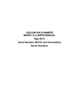
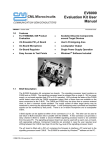
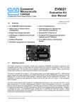
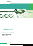
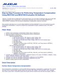
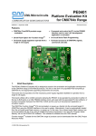
AN/Two-Way/9800A/1 July 1999
Using the EV9800 Rev A Evaluation Board with the CMX980A
Introduction
The new and updated CMX980A TETRA Baseband Processor is now available and in production. To support
designers working with the new device, CML have revised the EV9800 Evaluation Kit to Rev B (see note 3
(overleaf)). The new version of the Evaluation Kit is considerably improved. A DSP interface and connection
site for the Texas Instruments DSKPlus (TI320C54) DSP Development Kit is provided. A suite of software is
included; this is downloadable from a PC into the DSP card allowing comprehensive evaluation and testing of
the CMX980A.
The new EV9800 EvKit can be obtained from your local CML distributor or representative.
This CML application note describes how the previous revision (Rev A) of the EvKit can be modified to work
correctly with the final production release of the CMX980A.
Modifying the EV9800 Rev A EvKit
A few simple alterations are required:
The alterations involve the replacement of four resistors and a surface mount capacitor.
Replacing the four resistors
Figure 1 is taken from the EV9800 Evaluation Kit User Manual, Issue 1, Section 1.5 and should be used for
orientation. The alteration involves the removal of the four resistors R6, R7, R8 and R9 and then replacing them
with new components. The value of the replacement resistors is 6k2 ohms, 1% tolerance and rated at 250mW.
Caution: The through holes are plated thru’ and care should be taken not to damage them during component
removal and replacement operations. The recommended method is to cut through the resistor legs close to
the board. The wire can be removed with a pair of needle-nosed pliers while applying gentle heating with a
suitable soldering iron. A solder sucker or solder mop can then be used to remove excess solder.
J15
JP2
J16
JP1
N
C11
R8
DGND
R9 AGND
LK1
P
C12
J13
JP4
J14
JP3
C9
R6
R7
C10
N
U1
P
TP6
AGND
J12
JP9
C7
N
R2
FX980L6SKT
Figure 1 Location of Resistors: R6 to R9 on the EV9800 rev A
Replacing the surface mount capacitor (C6)
The other alteration is to replace the capacitor, C6, with a 'zero-ohm' surface mount (SM) resistor or wire link. It
should be noted that this capacitor is situated on the underside of the PCB, underneath the CMX980A device
socket.
Caution: The pads and connecting tracks are easily lifted from the board. The recommended method of removal
is with a proprietary desoldering tool. As an alternative it is possible to simply solder a 'zero-ohm' resistor over the
top of the existing capacitor.
It is recommended that you confirm that a short-circuit does exist between the two pads to which the zero-ohm'
resistor connects.
L2
L1
L4
C6
C3
L3
Figure 2 Location of Capacitor, C6 on the EV9800 rev A
Please note that:
1. The receive performance for low signal levels of a modified EV9800 Rev A PCB is not expected to be as good
as that for a Rev B PCB.
2. The Rev A PCB requires a special connecting cable and interface to connect the Evaluation Kit to the Texas
Instruments DSP card. Details of this interface are given in the first issue of the User Manual (UM9800/1).
The Rev B PCB includes a footprint for the DSP card, so no additional hardware is required.
3. If clarification is needed the Rev A board has PCB006A printed on the underside of the board whereas the later
Rev B board has PCB006B printed on the underside.
Note that this Application Note is intended to be used in conjunction with the current CML Product Datasheet; printed Specifications apply.
CML does not assume any responsibility for the use of any circuitry described. No circuit patent licences are implied
and CML reserves the right at any time without notice to change the said circuitry.
Consumer
Microcircuits
Limited
COMMUNICATION SEMICONDUCTORS
Oval Park - Langford - Maldon - Essex - CM9 6WG - England
Tel: +44 (0)1621 875500
Fax: +44 (0)1621 875600
e-mail: [email protected]
http://www.cmlmicro.co.uk/
© 1999 Consumer Microcircuits Limited