1
NEPTUNE: MOBILE MANIPULATOR WITH ADVANCED,
HUMAN ROBOT INTERACTION
by
PAVAN KANAJAR
Presented to the Faculty of the Graduate School of
The University of Texas at Arlington in Partial Fulfillment
of the Requirements
for the Degree of
MASTER OF SCIENCE IN ELECTRICAL ENGINEERING
THE UNIVERSITY OF TEXAS AT ARLINGTON
May 2011
Copyright © by Pavan Kanajar 2011
All Rights Reserved
ACKNOWLEDGEMENTS
I would like to thank my supervising professor Dr. Dan Popa for constantly motivating
and encouraging me, and also for his invaluable advice during the course of my studies. I would
also like to thank Dr. Frank Lewis and Dr. Vasillis Athitsos for their interest in my research and
for taking time to serve in my thesis committee.
I would like to extend my appreciation to Dr. Fillia Makedon, Dr. Dan Popa and CSE
Department, UTA for providing financial support during my graduate studies. I wish to thank my
colleagues Dr. Jartuwat Rajruangrabin, Isao Saito and Isura Ranatunga. I am grateful to Dr.
Fillia Makedon and Dr. Dan Popa for giving me the opportunity to work at the Heracleia Lab and
the NGS Lab.
Finally, I would like to express my deep gratitude to my parents who have encouraged
and motivated me and sponsored my graduate studies. I am also grateful to my mother, father
and sister for their sacrifice, encouragement and patience. I also thank all my friends who have
helped me throughout my career.
April 18, 2011
iii
ABSTRACT
NEPTUNE: MOBILE MANIPULATOR WITH ADVANCED,
HUMAN ROBOT INTERACTION
Pavan Kanajar, M.S.
The University of Texas at Arlington, 2011
Supervising Professor: Dan Popa
This thesis describes Neptune, a mobile manipulator designed as an assistive device
for task-related activities and rehabilitation of children with special needs. Neptune consists of a
mobile robot base and a 6DOF robotic arm, and it is interfaced to users via Wii Remote, iPad,
Neuro headset, a camera, and pressure sensors. These interfaces allow patients, therapists
and operators to interact with the robot in multiple ways, as may be appropriate in assistive
scenarios such as: direct physical interaction with the iPad, arm positioning exercises through
Wii remote, remote navigation and object retrieval through the environment via the Neuro
headset, etc. In this thesis we present an overview of the system and discuss its future uses in
rehabilitation of CP children.
In this thesis, we have investigated 5 different modalities of interaction with robots.
Motion sensing: we present a novel algorithm to map the Wii remote motions to the mobile
manipulator. This enables the user to guide the robot in a natural way by pointing the remote in
a specified manner.
Physical sensing: we present a novel approach to enhance human robot interactivity
through the use of force feedback with the force sensors. Visual sensing: we present a novel
iv
approach to enhance interaction of mobile manipulator through the use of visual servoing and
tracking. Interface devices: we present work on combining dynamic gesture based commands
from an interface device to improve the intuitiveness of control and planning of a multiple
degrees of freedom robot system through neural network based learning.
Neural Signal Sensing: The brain activity is read and feature extraction, classification
algorithms are applied to detect cognitive, affective and expressive features of the person
wearing the neuro headset. These features are mapped to operate the robot.
We propose an efficient way to coordinate multiple modalities sensing as generalized
interface for multiple robots. Performance metrics are proposed so that we have the quantitative
way to identify our interaction efficiency.
v
TABLE OF CONTENTS
ACKNOWLEDGEMENTS ................................................................................................................iii
ABSTRACT ..................................................................................................................................... iv
LIST OF ILLUSTRATIONS.............................................................................................................. ix
LIST OF TABLES ........................................................................................................................... xiii
Chapter
Page
1. INTRODUCTION……………………………………..……….. ........................................... 1
1.1 Motivation for Human Robot Interaction (HRI) ................................................. 1
1.2 Challenges involved in Human Robot Interaction ............................................ 3
1.3 Contribution of this Thesis................................................................................ 6
1.4 Thesis Organization ......................................................................................... 8
2. LITERATURE REVIEW ................................................................................................. 10
2.1 Background and Significance......................................................................... 10
2.2 Related Work.................................................................................................. 11
3. DESCRIPTION OF NEPTUNE AND INTERFACE DEVICES ...................................... 21
3.1 Harmonic 6 D.O.F. ARM ................................................................................ 22
3.1.1 Hardware Features ........................................................................ 22
3.1.2 Software Features .......................................................................... 26
3.2 LABO-3 Mobile Robot .................................................................................... 27
3.2.1 Hardware Features ........................................................................ 27
3.2.2 Software Features .......................................................................... 30
3.3 Wiimote .......................................................................................................... 31
3.3.1 Hardware Features ........................................................................ 31
3.3.2 Software Features .......................................................................... 33
vi
3.4 Epoc Neuro Headset ...................................................................................... 34
3.4.1 Hardware Features ........................................................................ 34
3.4.2 Software Features .......................................................................... 36
3.5 Flexi Force Sensor ......................................................................................... 38
3.5.1 Hardware Features ........................................................................ 38
3.5.2 Software Features .......................................................................... 39
3.6 IPAD ............................................................................................................... 39
4. HARMONIC ARM CONTROL USING WII REMOTE.................................................... 41
4.1 Analysis of information from Wii remote ........................................................ 41
4.2 Description of Algorithm ................................................................................. 47
4.3 Modifying Sampling time of Wii remote.......................................................... 52
4.4 Results ........................................................................................................... 53
5. CONTROL OF LABO 3 MOBILE ROBOT WITH NEURO HEADSET .......................... 59
5.1 BCI used for Control ....................................................................................... 59
5.2 Description of Algorithm ................................................................................. 63
5.3 Obstacle Avoidance with Mobile Robot LABO-3............................................ 67
5.4 Results ........................................................................................................... 70
6. FORCE AND VISUAL INTERACTION FOR NEPTUNE ASSISTIVE SYSTEM ........... 72
6.1 Introduction..................................................................................................... 72
6.2 Force Interaction Algorithm ............................................................................ 74
6.3 Experimental Results ..................................................................................... 77
6.4 Visual Servo Control Algorithm ...................................................................... 87
7. GESTURE RECOGNITION SYSTEM........................................................................... 96
7.1 Introduction..................................................................................................... 96
7.2 Neural Network based Gesture Recognition System................................... 100
7.3 Cross correlation based Gesture Recognition System ................................ 101
vii
7.4 Results ......................................................................................................... 102
8. CONCLUSION AND FUTURE WORK ........................................................................ 116
8.1 Conclusion.................................................................................................... 116
8.1.1 Harmonic Arm Control using Wiimote .......................................... 116
8.1.2 Control of LABO-3 Mobile robot using Neuro Headset ................ 117
8.1.3 Force feedback interaction ........................................................... 117
8.1.4 Gesture recognition system ......................................................... 117
8.2 Future work .................................................................................................. 118
8.2.1 Interaction via Neuro Headset ..................................................... 118
8.2.2 Human Robot Interaction ............................................................. 119
REFERENCES ............................................................................................................................. 120
BIOGRAPHICAL INFORMATION ................................................................................................ 125
viii
LIST OF ILLUSTRATIONS
Figure
Page
1.1 Neptune Mobile Manipulator ...................................................................................................... 6
2.1 Human Agent Model................................................................................................................. 11
2.2 Force feedback control system diagram .................................................................................. 20
3.1 Neptune Overall System Diagram............................................................................................ 21
3.2 Angle definitions in kinematics ................................................................................................. 23
3.3 DH coordinate system and angles on Harmonic Arm .............................................................. 24
3.4 Tool Coordinate System ........................................................................................................... 25
3.5 LABO-3 Mobile Robot .............................................................................................................. 27
3.6 Block diagram of the motor control for LABO-3 ....................................................................... 28
3.7 Bumper locations...................................................................................................................... 29
3.8 IR sensor locations ................................................................................................................... 30
3.9 Wii Remote ............................................................................................................................... 32
3.10 Emotiv Neuro Headset ........................................................................................................... 35
3.11 Headset communicates over Bluetooth with PC .................................................................... 35
3.12 Using the API to communicate with the EmoEngine.............................................................. 36
3.13 Flexi Force Sensor ................................................................................................................. 38
3.14 iPad ........................................................................................................................................ 40
4.1 Diagram shows the ground frame XYZ and remote frame X’Y’Z’ ............................................ 41
4.2 Shows the remote and ground frame for pitch action of remote .............................................. 42
4.3 Shows the remote and ground frame for both roll and pitch action of remote ......................... 43
4.4 Wii remote Coordinate System ................................................................................................ 44
4.5 Orientation Information for roll action ....................................................................................... 45
ix
4.6 Corresponding roll angles ........................................................................................................ 45
4.7 Orientation Information for pitch action .................................................................................... 46
4.8 Corresponding pitch angles ..................................................................................................... 46
4.9 Joint Motor locations of Neptune manipulator .......................................................................... 48
4.10 Flow Chart .............................................................................................................................. 51
4.11 Wii Remote orientation data for pitch variation ...................................................................... 54
4.12 Corresponding Joint angles for pitch variation ....................................................................... 54
4.13 Wii Remote orientation data for roll action with pitch ............................................................. 55
4.14 Corresponding Joint angles for roll action with pitch.............................................................. 55
4.15 Wii Remote orientation data for roll motion ............................................................................ 56
4.16 Corresponding Joint angles for roll motion ............................................................................ 57
4.17 Wii Remote orientation data for roll motion with high pitch .................................................... 57
4.18 Corresponding Joint angles for roll motion with high pitch .................................................... 58
5.1 Boredom levels of the User ...................................................................................................... 60
5.2 Excitement levels of the User ................................................................................................... 60
5.3 Eyebrow Furrow Extent ............................................................................................................ 61
5.4 Eyebrow Movements ................................................................................................................ 62
5.5 Smile Extent ............................................................................................................................. 62
5.6 Neptune overall system components (hardware and software) ............................................... 64
5.7 Initialization of server programs on LABO-3 linux .................................................................... 65
5.8 Sequence of message processing ........................................................................................... 65
5.9 Neuro Headset worn by the user ............................................................................................. 70
5.10 Snapshot shows the user controlling the mobile robot using neuro headset......................... 71
6.1 Neptune Manipulator holding the iPad ..................................................................................... 73
6.2 Overall System Diagram .......................................................................................................... 74
6.3 Force Sensors mounted on iPad .............................................................................................. 75
x
6.4 Force feedback based interaction block diagram .................................................................... 76
6.5 Force sensor measurements from sensor 1 ............................................................................ 77
6.6 Corresponding encoder values due to interaction ................................................................... 78
6.7 iPad (end effector) movement in space ................................................................................... 78
6.8 Force sensor measurements from Sensor 2 ............................................................................ 79
6.9 Corresponding encoder values due to interaction ................................................................... 79
6.10 iPad (end effector) movement in space ................................................................................. 80
6.11 Force sensor measurements from Sensor 3 .......................................................................... 81
6.12 Corresponding encoder values due to interaction ................................................................. 81
6.13 iPad (end effector) movement in space ................................................................................. 82
6.14 Force sensor measurements from sensor 4 .......................................................................... 82
6.15 Corresponding encoder values due to interaction ................................................................. 83
6.16 iPad (end effector) movement in space ................................................................................. 83
6.17 Force sensor measurements from Sensor 2 .......................................................................... 84
6.18 Corresponding encoder values due to interaction ................................................................. 84
6.19 iPad (end effector) movement in space ................................................................................. 85
6.20 Force sensor measurements from sensor 1 .......................................................................... 85
6.21 Corresponding encoder values due to interaction ................................................................. 86
6.22 iPad (end effector) movement in space ................................................................................. 86
6.23 Coordinate frame for the camera lens system ....................................................................... 89
6.24 Eye-in-Hand Configuration ..................................................................................................... 91
6.25 (a) Initial Configuration (b) Final Configuration ...................................................................... 93
6.26 Error in X coordinate .............................................................................................................. 94
6.27 Error in Y coordinate .............................................................................................................. 94
7.1 A simple mathematical model for a neuron .............................................................................. 97
7.2 Perceptron network consisting of 3 perceptron output units sharing 5 inputs ......................... 98
xi
7.3 Acceleration information along X axis .................................................................................... 102
7.4 Acceleration information along Y axis .................................................................................... 102
7.5 Acceleration information along Z axis .................................................................................... 103
7.6 Acceleration information along X axis .................................................................................... 103
7.7 Acceleration information along Y axis .................................................................................... 104
7.8 Acceleration information along Z axis .................................................................................... 104
7.9 Acceleration information along X axis .................................................................................... 106
7.10 Acceleration information along Y axis .................................................................................. 106
7.11 Acceleration information along Z axis .................................................................................. 107
7.12 Acceleration information along X axis .................................................................................. 107
7.13 Acceleration information along Y axis .................................................................................. 108
7.14 Acceleration information along Z axis .................................................................................. 108
7.15 Raw Delta information along X axis ..................................................................................... 110
7.16 Raw Delta information along Y axis ..................................................................................... 110
7.17 Processed Information along X axis..................................................................................... 111
7.18 Processed Information along Y axis..................................................................................... 111
7.19 Raw Delta information along X axis ..................................................................................... 113
7.20 Raw Delta information along Y axis ..................................................................................... 113
7.21 Processed Information along X axis..................................................................................... 114
7.22 Processed Information along Y axis..................................................................................... 114
xii
LIST OF TABLES
Table
Page
3.1 DH assignment for Harmonic Arm ........................................................................................ 25
7.1 Match percentage for line gesture (NN) .............................................................................. 105
7.2 Match percentage for line gesture (CC) .............................................................................. 105
7.3 Match percentage for circle gesture (NN) ........................................................................... 109
7.4 Match percentage for circle gesture (CC) ........................................................................... 109
7.5 Match percentage for circle gesture (NN) ........................................................................... 112
7.6 Match percentage for circle gesture (CC) ........................................................................... 112
7.7 Match percentage for nod gesture (NN).............................................................................. 115
7.8 Match percentage for nod gesture (CC).............................................................................. 115
xiii
CHAPTER 1
INTRODUCTION
1.1 Motivation for Human Robot Interaction (HRI)
Human Robot Interaction is the study of interactions between humans and robots.
Human Robot Interaction is a multidisciplinary field with contributions from robotics, humancomputer interaction, artificial intelligence, natural language understanding and social sciences.
Human Robot Interaction in the development of robotics systems enabling interaction
capabilities more similar to human-human interaction has become a hot research topic [16].
Most of the research in this area is carried with a goal to furnish robotics systems with
the function to observe, detect and respond to the modes of interaction that people apply
naturally with one another.
Social Robotics involves human robot interaction. Social robotics is an area of study
that focuses on the development of the robotic systems that cooperate with people or caters to
some of their social needs [17]. Human Robot Interaction plays a huge role in social robotics.
Human Robot Interaction is being studied in two major directions. One of the studies looks into
developing the models for robotic systems incorporating the social ability in these robots for
group coordination. Catering to the needs of the human using social abilities is another study
being conducted [57].
Some of the social robots developed in the past are ASIMO (the Honda Humanoid) and
Kismet from MIT which are capable of evoking social reaction from the humans and provide
entertainment to the human. Development of robotic systems established on the particular
requirements of the human continues, such as autonomous robotics system like AAAI Robotics
Challenge; care taking robots in health care [18]; and “human like” assistive robotics system
such as ISAC and Cog [20] [21]. Studies in Interpersonal interaction disciplines are necessary in
1
the applications of Social Robotics. Researches show that people react to intelligent robotic
systems identical to interpersonal situations, inclining to associate with human qualities [22]
[23].
Cerebral palsy (CP) is an umbrella term encompassing a group of non-progressive,
non-contagious motor conditions that cause physical disability in human development, chiefly in
the various areas of body movement [6]. Cerebral palsy is caused by damage to the motor
control centres of the developing brain and can occur during pregnancy, during childbirth or
after birth up to about age three. Resulting limits in movement and posture cause activity
limitation and are often accompanied by disturbances of sensation, depth perception and other
sight-based perceptual problems, communication ability, and sometimes even cognition;
sometimes a form of CP may be accompanied by epilepsy. Of the many types and subtypes of
CP, none of them has a known cure. CP kids have shown to interact well with robotic systems.
Robotics is a broad area such that people’s experience and expectations change
greatly with the interaction abilities. Robotic system used in the Assistive environment is
expected to use natural interface devices to meet the naturalistic expectations of the people.
Mori [51, 52], was among the first to suggest that people are likely to become familiar
with robots that exhibit human-like features, appearance and characteristics. However, if those
characteristics are not apparent, an “uncanny valley" is created which leads to feeling of
repulsion by humans.
Robots have been widely used in industry to perform repeatable tasks under the
guidance of the human operator. Robots are now being programmed by an operator to perform
tasks through a teaching pendant. After the teaching phase, the robot can store the trajectory in
the sequence of operations and the robot is run to perform the sequence of operation
repeatedly. With advancement in HRI the operator would eventually require less time in
teaching the robot and also work cooperatively with the robot.
2
In the recent past, the interest in robotic systems is raising and there has been a lot of
research with different types of interaction devices to improve the intimacy between the robots
and people. Methods like human-human interaction for human-robot interaction are applied for
efficient and effective interaction methods. Non verbal and verbal ability instead of just verbal
ability in the human-human interaction makes the exchange of information smoother [16].
Similarly a set of modalities are required in human robot interactions relevant for the situation.
Development of efficient methods for uninterrupted natural interaction is essential as the
expectations derived from increasingly realistic appearance of the robot becomes higher.
This thesis is conducting research about robot feedback, which demonstrates the
progress of the robot based on the user input. We applied the scheme of using expressions
from users with a Brain Computer Interface (BCI) device, to find out the most effective reaction
feedback for human robot interactions. A brain computer interface (BCI), is a direct
communication pathway between the brain and an external device such as a computer. On the
basis of the results obtained, a framework was designed for experimental human-robot
interaction and it was applied to an existing mobile manipulator robot.
1.2 Challenges involved in Human Robot Interaction
1). In HRI the robot should act on both human interaction input as well as via
autonomous robot intelligence through its sensory information. Action based on human inputs
is a key output for an HRI application. The robot would need to respond to the users in a timely
fashion, and thereby helping them with their needs. But it is also required for the robot to use
the sensory information and its own reasoning intelligence based on which it can reassess the
user commands and intent. For example, if an obstacle is placed in front of the robot and if the
user input was to move forward, we would like the robot to avoid the obstacle, but still reach a
position consistent with the human command. Therefore in this situation where the user was not
able to see the obstacle or if there was a false human intent, the robot must be intelligent
3
enough to avoid the obstacle. The robot employed for HRI must have both intelligence and
interaction capabilities. The challenge in adding this feature to the robot, is to determine when
the robot has to act on different modes i.e., interaction mode and intelligence mode. The
interaction mode should also verify that the robot has satisfied the user in reaching the goal.
2). Real-time performance: Real-time response of the system is one of the challenges
in HRI. Real time performance is required to successfully maintain appropriate interactive rates
of the system to dynamically engage with the human. There are performance latencies in
several system functions which includes visual perception, haptic perception, facial gesture
recognition and motion sensing [17]. Although each of these sensing systems does not perform
at human rates, these need to operate fast enough to allow a human engage with the robot
comfortably. The robot must provide important feedback to the human through actions that we
intuitively use to adjust the robot’s level of performance.
3). Recognizing human gestures: Interpretation of human’s social cues is a key to
successful HRI. There are two scenarios where the robot can interpret the people’s social cues
[57]. Gesture is one of the human social cues which could be used to direct the robot’s actions.
Interaction by touch and pushing (physical interaction) is another important social cue which can
improve the communication. Robotic system behavior can be formed and reinforced using these
interpretations as the main teaching tool. Another is the ability of humans to direct the robot’s
attention using natural cues via a BCI device.
Making the human robot interaction (HRI) effective, realistic and efficient is important for
assistive robotic systems. The human and robot must be able to interact clearly regarding their
goals, program and accomplishments and cooperate to work out the challenges, specifically
during times which surpass the robot’s autonomous potential; and communicate via different
4
modalities like gestures and physical interactions. To accomplish these goals, a number of HRI
challenges must be addressed by researchers.
4). Interaction architectures are the software models which reinforce the human robot
interaction. A group of main services like event handling, data sharing, etc. are furnished by
these architectures to support different types of interactive devices, and enable humancentered interaction instead of device centered interactions
Significant research efforts concentrating on software models for interaction has been
made in the past few years.
Most of these models focus on supporting context aware
applications, but only some are developed for robotics. The range of interaction abilities and
data needs are not supported by these current models which are required for human robot
interaction.
5). A number of hardware challenges arising from the sensors, actuators, end effectors,
power and real time control needs to be addressed. The reliability of the sensory information is
one the foremost challenges. For instance, the IR sensors would fail to detect any obstacles
beyond 15 cm range and sometimes fails if the object is too close (distance < .5 cm). Some of
the other difficulties involve eliminating the noisy information from the sensors by filtering the
information. The ability of the actuators to provide desired torque is limited by the maximum
torque of the joint motors of the system. The type of end-effector on the robot would limit the
types of objects that can be grasped. The runtime of the robot is determined by the capacity of
its battery pack. Since the control loop must be closed at a faster rate to achieve the desired
output response, Real time control is another important aspect for the performance of a control
scheme.
5
1.3 Contribution of this Thesis
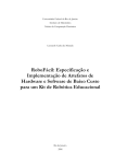
Neptune is a robotic mobile manipulator that was configured at Heracleia lab in spring
of 2010. Neptune base has the ability to autonomously navigate around the environment and
manipulate the object in this environment with the help of a manipulator. The robotic
manipulator on the system is called Harmonic Arm and mobile platform is called LABO-3. The
Harmonic Arm is a robotic manipulator used for pick and place applications. The manipulator
has a gripper at the end effectors to grasp objects. The Harmonic Arm has 6 degrees of
th
freedom. The 6 degree of freedom is in the gripper.
Figure 1.1 Neptune Mobile Manipulator
In this thesis we developed several interaction algorithms for human robot interaction.
Different new interface devices were employed for the interaction between the user and robot.
This thesis makes the following contributions to the research in human robot interaction in order
to improve the interaction between human and robot.
6
1) Neptune mobile manipulator was interfaced to users via Wii remote and Neuro
Headset: Interaction algorithms for controlling the Harmonic arm of Neptune robot using
Wii remote have been formulated. The method allows the user to guide the arm using
the Wii remote to perform pick and place type of operations. Interaction algorithm for
control of LABO-3 mobile robot using Neuro headset has been developed. A mapping
scheme was proposed to map the user expressions to navigate the mobile robot in the
environment [53].
2) Gesture Recognition via Wii remote and Neuro headset: A gesture recognition
algorithm using a neural network/ cross correlation has been formulated. The gestures
are made using the interface devices like Wii remote and Neuro headset. The user
makes gestures using hand in the case of Wii remote. And in the case of Neuro
headset makes gestures using head movements. The scheme is able to accurately
distinguish different gestures like line, circle gestures etc [53].
3) Force Feedback Control via Flexi Force Sensors: A force feedback control algorithm
using the force sensors on the end-effector (iPad) has been designed. The scheme
allows the user to interact with the robot holding iPad (end-effector) via these force
sensors mounted on the system. This method allows the user to change the position
and orientation of the iPad interacting with the sensors [53].
4) Visual Servo Control: Control algorithm for visual servoing for the Neptune robot with
eye in hand configuration has been developed. A desired view for the object with
respect to the robot end-effector was considered. Using visual servo control, the robot
was able to move to the desired configuration which resulted in the desired view of the
object in the camera view [53].
7
1.4 Thesis Organization
In chapter 3, we describe the overall system with the interface components like Wii
remote, Epoc neuro headset, Flexi force sensor and iPad used for interaction with Neptune
robot. We give an overview of the hardware features and software features of the Neptune
System. Also discuss the software APIs used to access and send commands to the Neptune
robot. The features of the interfaces devices like hardware features and the software libraries
used to access the sensor readings from the interface devices are discussed.
In chapter 4, interaction with multiple degrees of freedom of Harmonic arm is discussed.
In this chapter, we focus on interacting with Harmonics arm through the interface device Wii
remote. Analysis of information from the Wii remote is presented. We are interested in
developing a mapping scheme that is intuitive and easy to use for operators. Then using this
mapping scheme we show how a pick and place operation could be performed.
Chapter 5 presents interaction with the LABO-3 mobile robot using Epoc neuro
headset. In this chapter we discuss how the Neuro headset can be used to detect expressions
and emotions of the user wearing the headset. We propose a mapping scheme, to use the
expressions of the user wearing the headset to control the navigation of mobile robot in the
environment. Also we discuss the obstacle avoidance algorithms for the mobile robot using the
sensory information from the IR and bump sensors on the robot.
In Chapter 6, a physical and visual interaction scheme for Neptune robot using sensory
information from force sensors and camera is introduced. We propose a scheme for positioning
the iPad screen with the robot holding the iPad at the end-effector through the force sensors
and camera mounted on the iPad. We discuss the algorithms for force feedback control used for
physical interaction scheme and visual servo control for the visual interaction scheme to
automatically adjust the screen position for the user.
Chapter 7 presents the gesture recognition system using the interface devices like Wii
remote and Neuro headset. Here we discuss two approaches used for the gesture recognition
8
system i.e., Neural networks and Cross correlation based approaches. Also the procedure for
training the recognition system for gestures like making a line and circle using the sensory
information from the interface devices are discussed. The recognition results based on the
mean squared error for the test set of gestures are shown.
Finally in the chapter 8, we provide a summary of the thesis and the list the future
works.
9
CHAPTER 2
LITERATURE REVIEW
2.1 Background and Significance
In the past few decades, robot aided therapy has enabled high performance to attain
acceptance in the field of rehabilitation [24] because the new trend in HRI furnishes effective
methods to work out the robot aided rehabilitation tasks in equivalence with the manual therapy
[25] [26]. There is a lot of literature pertaining to robot aided therapy as well as commercial
robots used for rehabilitating the human arm motions, where Human Robot Interaction is used
in assisting the humans [27].
The rehabilitation robots are classified in two types of robots. One is the end effector
based robots used for arm therapy. Other one used for the rehabilitation is the exoskeleton
[28].
Exoskeleton type of robot also can assist people in performing task easily with almost
no fatigue [28]. The exoskeleton robots can determine the exact arm pose and their time
variations through the joint axes of the robot which are tightly attached to the human limbs.
An exoskeleton robot, Armin II has 6 degrees of freedom is used in human arm
rehabilitation in addition with virtual reality worlds to help post stroke patients.
These exoskeleton robots incorporate proportional-derivative (PD) controller plus
gravity compensator to obtain the interactive forces, which are calculated from the virtual reality
interaction.
In the work presented in [31] a 7 degree of freedom upper limb exoskeleton was used
for therapeutic diagnostics and for physiotherapy. Techniques for control schemes for enabling
stability or rehabilitation techniques are not discussed in these papers.
10
2.2 Related Work
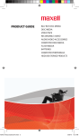
A Model for Human robot interaction, Human Agent System Model has been discussed
in [33]. Here the Human Agent Model is established on the basis of personal interaction. Figure
2.1 shows a diagram of various components involved in human agent system. The Human
Agent receives the input from the Human Input Agents (HIA) i.e., in turn from the users and
functions on a Human Database. This model has main features that provide the robotic system
with a sensing ability, awareness and social interaction abilities.
These features are termed as agents. These agents help to communicate information
from one section of the component to the other; also these agents have the ability to function on
its own as independent entities. Combing these agents we build a higher level agent and one of
the examples is a human agent, which is a collection of these primitive agents
Figure 2.1 Human Agent Model [33]
11
A. Human Agent
The Robot internal description of peoples in the environment is called Human agent.
Encapsulating or modeling of human is the goal of the human agent.
The Human Agent
considers various aspects of interaction as mentioned in [33].
It keeps up with the physical, task related and cognitive aspects of the human. It is
composed of several functional modules that perform two key roles. The Monitoring Agent
registers for people and people-related events in the environment. The Interaction Agent makes
decisions for the robot’s involvement for the interaction, based on its knowledge of social
situations and the current state of the interaction environment.
B. Monitoring Agent
Sensing is represented by a Monitoring agent that checks the characteristics and
statuses in the world that display that people are active. The monitoring agent works such that
the system can receive the user inputs from different interactive devices like visual (camera) or
motion sensing (accelerometer).
Different modes for sensing human interaction are used in the approach. The method is
based on the approach that involves interpersonal interactions which uses several ways of
interaction.
Independent operation modules called as Human input agents detect for particular
desired features like face or movement and furnish their recognition results to the Monitoring
agent. These user input results are connected to different functionalities of the monitoring agent.
HIA executes the detection functions like speech recognition and face recognition to observe
the world.
12
C. Interaction Agent
The second important characteristic is executing required actions for interaction results
obtained from results of the monitoring agents. This agent organizes the role of the robotic
system in the interaction. The user input and knowledge of the situation are processed by the
interaction agent to decide the appropriate response.
•
Human Intention: A description of human intention is made by the agent and it employs
the present status of the interaction to accomplish a task. Here the user input and
knowledge of the current situation are processed by the interaction agent to decide the
appropriate response.
•
Socialness: The sections of the human agent system discussed before enables the
robotic system to detect desired characteristics which are pertinent to the social
interaction. But the robot must perform action and give responses on the basis of data
about the status of the environment socially to demonstrate the social ability.
iPad Games:
Past work has proposed using touch screen programmable games to treat CP
conditions. These games target metrics to measure delay of response, score, stamina /duration
of play, accuracy of hand/motor motion. Also such games will increase the performance of kids
with CP with daily sessions [7]. CPLAY is a game with changeable levels of difficulty to provide
controlled audio and visual stimulus to children with CP and thus make possible a desired motor
response [64].
iPad has been extensively used for entertainment purposes where the user can browse
share and enjoy the web and other services through bigger screen than the mobile devices. The
inclusion of touch screen and other acceleration sensors in the device has made iPad an
13
interesting device through which the user can interact. Previous work has shown that children
with CP do better after series of game sessions on iPad, lasting for 20 to 40 minutes.
Assistive and Rehabilitation Robotics:
Robot assisted suite for home based therapy with the help of assistive devices to aid
the patient’s requirements for individual and fun therapy was presented in [26]. Force feedback
through joysticks and wheel systems were with used with custom based software for therapy.
Games for exercise through a planar 2DOF robot and a wrist robot were employed for shoulder
and wrist pronation.
Development of a rehabilitation robot for ADL (Activities of Daily Living) training was
discussed [60]. Probable models for exercise and trajectory planning to precisely translate the
innate movements of the wrist during an Activities of Daily Living (ADL) task were presented.
The rehabilitation experiments resulted in smoothness and reduced time for movements
reflecting improvement in the motor ability and control of the patient.
Smooth trajectory for activities like drinking and feeding based on the motion data
analysis of these activities was modeled [61]. Using this model on ADLER system, different
trajectories for goal based tasks and direction changes when the object changes position was
generated. In the case studies with the subjects resulted in a more natural and realistic
movements with the prediction of wrist paths by the ADLER system. Also it was suggested that
the system will perform better with visual servo algorithms to plan the trajectory during robotassistive therapy.
A description of motivation was presented in [62] for robot assisted therapy and
discusses the difficulties in impaired arm use in the real environment. Using the robotic system
three interesting case studies was discussed. The plans discussed were (1) embed therapy via
a structure that presents patients with monitoring and interaction with therapists, (2) embed
14
therapy into entertaining, game like actions, and (3) embed therapy within patient-centered life
like practical activities
Human Robot Interaction:
Realistic human robot interaction was achieved through an effective and robust tracker
for humanoid head, LILLY via visual servoing to track people at ARRI’s humanoid lab [47]. The
visual servo routines for tracking were optimized though minimization of a cost function for the
servo controller is presented in [47]. Also inclusion of the learning phase for the control
algorithm was designed through a reward function in TD reinforcement learning approach,
showed that the tracking accuracy was greatly improved for the humanoid head [54].
A tracking system for an object through pose prediction via Extend Kalman Filters and
visual feedback control algorithms was presented in [56]. The servo controllers were tuned
through Ziegler-Nichols PID tuning methods and tracking algorithms were tested on a PTZ
camera. Also this paper proposed an optimization approach for realistic motion in robot with
real-time vision based feedback control. Results presented showed that tracking through the
neck and eye motions for the robot actor resulting from this scheme was realistic in comparison
to that of humans [55] [54].
Reinforcement learning to improve interactivity and effectiveness in the human robot
interaction was discussed in [43]. Adaptive mapping algorithms for interface devices were
employed with learning based on reward function from the user. A model for updating the
interface mapping was proposed where the policy of interface mapping, value functions and
state property weights were updated based on the metric evaluation of the actions was
performed. [43] shows robustness of the algorithm in mapping interfaces which provided a
technique where the robot interactive actions were not only based on the user input but also
learning from the results of the action performed. The algorithm showed increased accuracy
and robustness as the number of trails conducted increased [54].
15
A dynamic interface based on the cognitive and emotions of the user for human robot
interaction were presented in [45]. Here the cognitive and emotion statuses were extracted from
the video based eye tracker system capable of tracking the user’s eye gaze. A novel gesture
recognition algorithm was presented in [41] that is precise and efficient using vision and is
robust in recognition, even when the user gestures without aiding devices in front of a cluttered
background. The gestures recognition system algorithm developed increased the accuracy of
detection rate 10 fold from 8.5 % to 100% in comparison with CDP method of Oka [59], which
makes assumption of reliable hand detection results. A statistical model for variation in template
based gestures was used. The algorithm proposed a hybrid approach, where a Gaussian model
was predicted using observational probabilities (similar to Hidden Markov Model), but applied
uniform transition probability model of DTW [63].
[46] presented image based visual servoing technique employed using a camera for
navigating a mobile robot towards a desired configuration. The proposed algorithm is based on
the epipolar geometry dictated by the initial and final desired configuration of the mobile robot
which results in a desired view in the camera. Simulations and experiments were carried out
showing the accuracy of the proposed vision based control algorithm.
Wii Remote:
Many related work has been done for development of interface software for the Wii
remote. Software libraries for connecting the Wii remote to a PC, parsing the input data sent
from the remote. These libraries are developed for all platforms like Windows, Linux and Mac
OS. Open source communities have developed these libraries and are freely available for
download. The Wii remote has a high standard of input and output added with the ability of
bluetooth connectivity has made it quite popular interactive device for research and alternative
interaction strategies for existing applications. Several projects initially developed in the
16
community used motion sensing and orientation sensing capabilities for the robotic control and
other interactive purposes.
The Wii remote has been used as a mouse to send mouse control inputs to the
computer which led in some of the people using this device to play mouse based games and
folder navigation. But these applications have limitations since the Wii remote would need the
IR sensor bars to make the remote capable of point tracking. When you hold the Wii remote, the
camera sees the IR dot movements primarily in correspondence to the controller’s yaw, pitch,
and roll. The tracking information obtained from the remote is not sensitive to the translational
movement. However this attribute of the remote is reversed when the remote is stationary and
the IR sensor bar moves [1].
The translation accounts for the dot movement and the tracking data is not sensitive to
the orientation. This arrangement is used for motion capture systems in interaction games
which makes the remote into a comparatively a high performance system for motion tracking
systems.
The Personal Mobility Robot (PMR) is a robotic wheelchair that is similar to the segway
and self-balances on two wheels [32]. The Robot is based on a platform developed by Toyota,
comes with a manual controller that the people can use to change speed and direction. Now
two University of Tokyo researchers have upgraded the machine, making it controllable by a Wii
remote controller. The PMR project is part of research initiative at the University of Tokyo
developed to help elderly and people with disabilities remain independent and mobile. The robot
speed is controlled by moving the remote up and down i.e., varying the pitch of the remote. And
robotic chair makes right turns when the user rolls the remote right and turns left when rolled to
left.
The gesture recognition in Wii games is accomplished by the use of accelerometer data
or the IR camera tracking data, but it is limited relative to what’s possible in research systems
[1]. The features of the accelerometer and orientation data must be studied to adapt the gesture
17
recognition algorithm. These data inputs from the Wii remote provides new and unique
challenges for the recognition systems to correctly analyze and parameterize variations in
speed, orientation for a given gesture. A number of researchers are analyzing this issue, but it
still remains an open research area [1]. A method for performing gesture detection using the
accelerometer data with a robust method would be a major contribution for large variety of
motion –sensing applications.
The Wii remote was employed for tracking methods using human motion models with
good precision for easy tasks [2]. Very intuitive control was achieved where even new users
were able to control and command a robot arm through simple tasks after a few practice and
few instructions. Using nominal jerky trajectories in the approach, human motion models were
used to accurately track the input from the user to position control the desired goal with minute
error. Prediction of tracking was performed, so that the real time data input read are analyzed
which can be used in simultaneous task control with user input.
An algorithm was presented in [50] where using the Nintendo Wii remote the user can
go towards the target points while directing the remote at the robot; then the robot would follow
the user. Here the built in camera and accelerometer in the Wii remote was used along with a
few LEDS on the robot. Hand gestures through the Wiimote were recognized through a filter
and an Interacting Multiple Model (IMM) kalman. These interactive algorithms had been
examined with 12 volunteers interested in new technology but have never operated a robot. The
experiments resulted in most users being able to control the robot within a few minutes and
were able to guide it to three target place in the environment.
Brain Computer Interface:
Some of the works are presented in [40] with the aim of using BCI (brain computer
interfaces) with the mobile robots. The goals of the experiment were: (i) to examine an improved
BCI experience with the aid of a robot, so that the neuro signals are stronger stimulate. (ii) to
18
use a remotely controlled robot through a paralyzed subject via a Brain computer interface
along with a graphic user. Some of the potential applications like robotic guide for museum
using PeopleBot and Pioneer3 robot experiments were presented; where the robot transmitted
visual images of the scene to the patient.
Simulation experiments were presented in [28] showing that neuro signals extracted
from the BCI was better desired signals. Using these prominent feature signals one can retrieve
the type of motion or sensing of people via BCI. Rehabilitation robots built on this technology
allow the patient to control the robot without the need of muscle or peripheral nerves activity.
These experiments developed a new way of communication for patients during rehabilitation
therapy with the help of a BCI device.
The BCI user interface was examined using a Matlab code that simulates the WMRA
motion and control the physical WMRA (Wheelchair-Mounted Robotic Arm) system in teleoperation mode [39]. This simulation was conducted with various user interfaces. The program
was designed to deliver different useful results and data though the simulation process for
analysis and diagnosis of any possible problem that may occur during the task execution while
the arm is running.
The WMRA gets the input from the user through the BCI device. Three target were
shown in the experiment, after that the user’s task was to concentrate on a desired feature from
5x3 visual matrix. The movement of the WMRA in the simulation experiment had 100%
accuracy same as the BCI input.
The speed with which the information is transmitted to robot from the BCI device is
important. Since the robot requires these signals continuously in order to move along the
desired path.
19
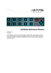
Physical Interaction through Force Sensors:
Algorithm for Real-time control interactions in human robot interaction (HRI) sharing
common workspace were discussed in the paper [15]. Unlike traditional robotic manipulators,
we assume that the interaction between human and robot is not restricted to the wrist/endeffector of the robot, but that it can happen anywhere along the kinematic chain. Interaction
forces are only monitored in some directions, and predicted in other direction through an
Extended Kalman Filter.
Sensor measurements are obtained through the joint encoders and force measurement
through pressure sensors mounted on the robot links. Observational results were presented
with a Phantom Omni haptics device where the control algorithm execution was compared
during the impedance response with and without the force measurements from the sensors.
The Kalman filters were employed to predict the pushing force by the user, which in turn is used
to guide the robot arm to a desired pose. Impedance control and Computed torque control
scheme was used as shown in the feedback control system diagram below.
Figure 2.2 Force feedback control system diagram [15]
20
CHAPTER 3
DESCRIPTION OF NEPTUNE AND INTERFACE DEVICES
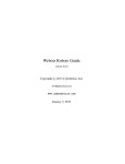
Neptune overall system diagram is shown in the figure with all the system components
and including the interaction algorithm associated with some of the interface devices. The
system PC connects to the Neptune mobile manipulator via Wi-Fi or Ethernet which runs the
interaction and control algorithms to actuate the robot using sensory information from different
new interface devices.
Figure 3.1 Neptune Overall System Diagram
21
Also these interaction and control algorithms can be run on the base PC on the mobile
robot base using Robot Operating System (ROS). Interface devices like the Wii remote and
Epoc Neuro headset communicates to the system PC via Bluetooth. Some of the others
interface devices on the Neptune mobile manipulator like the encoders relay information about
joint encoder position of the robot. And the others interface devices like the force sensors,
camera and iPad are mounted on the Neptune robot to perform interaction routines. The patient
would use the rehabilitation games on the iPad and the corresponding interaction results are
recorded by the system.
3.1 Harmonic 6 D.O.F. ARM
3.1.1 Hardware Features
The Harmonic Arm is based on a single-board computer (SBC) equipped with a
PowerPC-based Freescale MPC5200 processor that provides 750 MIPS (millions of instructions
per second) of performance. The robot has six Texas Instruments (TI) TMS320 32-bit motor
controllers, one for each axis. It is built around a CAN bus architecture, the robot also has
option for Ethernet and USB ports. The Harmonic Arm has three operation modes: control,
standalone direct, and a standalone RPC/Web-services mode that supports technologies such
as SOAP and Ajax for web-based control. The embedded Linux version of Katana runs a 2.4.25
Linux kernel that is said to be optimized for industrial high availability.
The robot is developed with the Denx Embedded Linux Development Kit (ELDK)
software Development kit (SDK), an open-source Linux distribution and development tool suite.
The Harmonic Robotic Arm is used for handling, measurement, or testing applications in
assembly, production, and laboratory automation. The robot is called an "intelligent" industrial
robotic arm with safety features which allows it to work directly in cooperation with human
operators without the need for any additional safeguards or fences.
22
Harmonic Arm 6M4D software differs from the angles calculated in the case of
kinematics in accordance with the modified Denavit-Hartenberg convention. The illustrations
that follow (Figure 3.2) show the angle definitions for Harmonic Arm as they are used in the
kinematics. The angles in the kinematics are defined in accordance with the “right-hand rule”.
Figure 3.2 Angle definitions in kinematics [65]
The positive encoder direction is again defined differently; although it is set by the
integration of the motors. The following formulae should be used for encoder to angle
conversion (in accordance with mDH) and vice versa:
23
(3.1)
(3.2)
where θa is angle offset, d is the rotation direction, e is encoder reading, eo is encoder
offset, epc is total encoder range
range.
The angle offset (angle of the calibration stop), rotation direction (comparison of the
direction of rotation between encoder and angle), encoder offset (encoder value at calibration
stop) and total encoder range (number of encoders per 360° revolution) are determ ined by the
hardware, geometry
ry and calibration of the robot.
DH Frame assignment for Harmonic Arm
Figure 3.3 DH coordinate system and angles on Harmonic Arm [65]
24
Table 3
3.1 DH assignment for Harmonic Arm [65]
The tool coordinate system is located in the robot’s tool. The position is defined by the
tool centre point (TCP). The position and orientation of the tool coordinate system are defined
as translatory and rotary transformations of the basic coordinate syst
system. Z-X-Z
Z Euler angles are
used for orientation. As the tool coordinate system moves with the tool, its position in relation to
it always remains the same, even if its position in space changes. The tool coordinate system is
also a right-handed
handed system and is defined by the following vectors: xtool, ytool and ztool. The
positive ztool axis always points towards the tool, away from the robot. If a gripper has been
mounted, the tool coordinate system will be entered as per standard (in other words, as
illustrated in Figure 3.4)
Figure 3.4 Tool Coordinate System [65]
25
3.1.2 Software Features
Neuronics offers a Katana Native Interface (KNI) C++ library for control application
development which allows the lowest interface level control. A control interface is also available
directly on the robot, with interfaces in C++, C#.
For non-programmers, a GUI-based application programming interface (API) called
Katana4D, which is targeted at industrial applications, and offers a built-in scripting language.
Developers can move the robot arm into the desired position by hand, and Katana4D detects
the position, generating the appropriate code, says the company. Katana4D is also said to
provide AI algorithms for path optimization and adaptation, and can automatically convert
applications to Python for deployment on the Katana in standalone mode. It is said to operate in
three modes: control, standalone direct, and a standalone RPC/Web-services mode.
The Katana Native Interface KNI is an open source software library for controlling the
Katana robot. KNI is written in C++ and structured so that it can easily be ported to other
languages and frameworks. The code is non-platform-specific and can be compiled under both
Windows (with the MS Visual C++ Compiler) and Linux (with the GNU Compiler Tool chain).
Since the KNI abstracts the underlying layers, applications can be written for the Katana without
having to become involved in the details of the system. It takes just a few function calls to
connect and initialize the robot. The protocol for controlling the robot from the PC is abstracted
in its entirety. The KNI features an implementation of robot kinematics and path calculation
routines for the synchronous control of all axes and the traversing of paths in space with the end
effector. The openness of the common sources also makes the KNI the ideal tool for research
and training, since the entire implementation can be traced, as well as modified and adapted at
will.
The Katana is also has the ability to run as an independent stand-alone unit, without
requiring an external control host. The Katana supports both Windows and Linux platforms. The
Linux version of the Katana allows low-level access to the robot’s Linux control board, and
26
comes with system, communication, and motion libraries available as open source packages.
This open source access provides application opportunities that will allow fast development of
the existing routine to control the arm.
3.2 LABO-3 Mobile Robot
3.2.1 Hardware Features
LABO-3 (Figure 3.4) is a small-size high-payload intelligent robot platform for indoor
use. LABO-3 is designed with a top to which users may attach equipment of their own for
research purposes. With its two-wheel differential drive, LABO-3 can turn with virtually zero
turning radius. LABO-3 is equipped with infrared (IR) obstacle detection sensors and bumpers
(Figure 3.5). With behavior-based AI technology, LABO-3 can run autonomously and
continuously in complex environments. All the processing to control the robot is executed on
board computer.
Figure 3.5 LABO-3 Mobile Robot [66]
27
LABO-3 has 10 infrared sensors: six at the front, one on each side, and two at the back.
There is also one set of bumper sensors at the front and another at the back of the robot. The
front bumper sensors detect obstacles on the following five directions: outside left, center left,
middle, center right, and outside right. The back bumper sensors detect obstacles to their right
and their left. The motors are located at the front wheels. LABO-3 uses two independent
differential drives, giving it a zero turning radius. Two sealed, lead-acid batteries are located in
the center of the robot's body. The two batteries provide a total capacity of 408Wh.
The control signals from the interface board include Pulse-Width Modulation (PWM),
Brake and Direction for each motor. Those signals control an H-bridge on the amplifier board.
On the motor controller connector, PWM is referred to as Speed. The PWM signal is amplified
by the motor controller board, and this is what controls the amount of power to the motors. The
Direction signal controls which way the motors turn, and the Brake signal can be used to disable
the motor at any time. The encoder pulse output signals are buffered and connected to the
Speed signal. The encoder provides 100 pulses per revolution. The PC/104 interface board
uses the 82C54 timer/counter to count the pulses. On the Vesta board, the TPU handles the
pulse counting. On the Vesta board, the TPU only counts the pulses and the position (and
speed) of each motor is calculated using the D signal to determine the direction. SENS
measures the current in H-Bridge. This is connected to the Analog- Digital Converter on the
interface board, and then converted to digital signals to detect over current.
.
Figure 3.6 Block diagram of the motor control for LABO-3 [66]
28
Bumper Sensor Inputs:
The bumper register is an 8-bit buffer connected to the bumper inputs. Each input is
connected to a 10k pull-up resistor. When something hits the bumper, it closes a button that
resets one of the bits to 0. Normally, when nothing is in contact with the bumper, reading from
the bumper register should return 0xFF (i.e. all bits high). Figure 3.7 shows the locations the
button groups and their corresponding bit positions.
Figure 3.7 Bumper locations [66]
IR Sensor Input:
The location of each of the IR sensors is indicated in figure 3.8. This is the order in
which the sensors values are stored in software. The IR sensor output ranges between 2.4V
when an obstacle is close (10cm) down to 0.4V when there are no obstacles within range
(approximately 80cm). The analog signal from the IR sensor is converted to a digital signal by
an 8-bit analog-digital converter (ADC). Since the ADC converts voltages in a 5 volt range, you
can expect values from the IR sensors to be between 20 (no obstacle detected) and 122
(obstacle about 10cm away). Note that the IR sensor is unable to correctly detect obstacles that
are closer than 10cm.
29
Figure 3.8 IR sensor locations [66]
3.2.2 Software Features
The programming language used is C for the mobile robot. The Library functions
provide services such as LABO-3's basic sensing, motor control, and serial communication.
Also there are functions for periodic processing.
The lcd functions provide an interface to the LCD driver. Writing to the LCD can take a
relatively long time, so these functions should not be called from a function that has critical
timing requirements.
Using sensor functions getIRs the status of the IR sensor on board can be monitored.
Before reading the sensors it must be initialed by calling initIR function. The IR data is stored in
an array of 12 integer values passed into the function. The IR parameter must be able to hold at
least 12 integers. The ADC converts the analog signals to 8-bit values, so the range of data is
0-255. Using getBumper function we can monitor the status of the bumpers on the robot.
30
Using setMotorPower function we can turn on the motor using the parameter
powerState. If the parameter powerState is 0, the motor power is switched off; otherwise, the
power is turned on. Setting the motor power state also enables (if power is turn on) or disables
(if power is turned off) the closed loop motor control functions.
3.3 Wiimote
3.3.1 Hardware Features
Wiimote is a handheld device resembling a television remote, but in addition to buttons,
it contains a 3-axis accelerometer, a high-resolution high speed IR camera, a speaker, a
vibration motor, and wireless bluetooth connectivity. This makes the Wii remote one of the most
sophisticated PC-compatible input devices available today; together with the game console’s
success, it’s also one of most common. The Wii remote is an impressively cost-effective and
capable platform for exploring interaction research. It has an ADXL330, a 3-axis linear
accelerometer from Analog Devices manufacturer. It provides the Wii remote’s motion- sensing
capability. It has a +/−3 g sensitivity range, resolution of 8 bits per axis, and a 100 Hz update
rate. The Wii remote has 12 buttons. Four are arranged in a standard directional pad layout.
One button is on the bottom providing a trigger-like affordance for the index finger. The
remaining seven buttons are intended to be used by the thumb.
A small vibration motor provides tactile feedback. The motor is similar to those used in
cell phones. The motor state has only binary control (on and off), but you can vary the feedback
intensity by pulsing the motor activation that is, by rapidly turning the motor on and off at
different duty cycles. Communication runs over a wireless bluetooth connection. The connection
uses a Broadcom 2042 chip, which Broadcom designed for devices that conform to the
Bluetooth Human Interface Device standard, such as keyboards and mice. The remote isn’t
100 percent compliant with the HID standard, but it can connect to many Bluetooth-capable
computers.
31
Figure 3.9 Wii Remote [67]
The onboard memory is approximately 5.5 Kbytes. It’s used for adjusting the device
settings, maintaining output state, and storing data. Nintendo designed it to let users transport
and store a personal profile, called Mii. This memory allows data and identity to be physically
associated to a given remote.
Bluetooth stack (Bluetooth software) must implement all the full bluetooth specification
to parse advanced inputs from a device like the Wii remote. There are 3 choices for bluetooth
stack BlueSoleil Stack, WIDCOMM Stack and Toshiba Stack. We use Bluesoleil stack.
Now when the device is paired, the Wii remote is implemented as a HID device. This
may be thought of as a serial device over USB. You can send commands to trigger rumble, turn
on and off the blue lights, etc. To get reports of buttons, accelerometer, etc you can either poll it,
or receive updates. HID, data is sent and received as "reports". Simply, it is a data buffer of a
pre-defined length with a header that determines the report contained in the buffer. The Wii
remote will send and can receive various reports, all of which are 22 bytes in length
32
3.3.2 Software Features
WiimoteLib is a .NET managed library for using Wii Remote and extension controllers
from .NET application. The Nintendo Wiimote can be accessed in C# and VB.NET [71]. The API
provides a class Wiimote which allows to add a new Wiimote class to each new Wiimote found
on the bluetooth range. FindAllWiimotes is the routine which helps to detect all the remote in the
bluetooth range of the computer. To initiate connection with the remote it provides a connect
function to be used within try catch statement with WiimoteNotFoundException handler routine
to establish connection. Also the library provides function to disconnect the remote from the
program. Once the device has successfully paired we can read the status of the remote using
event based report. Data can be retrieved from the API in two ways: events and polling. In
event mode, one must subscribe to the WiimoteChanged event as shown above. Then, when
data is sent from the Wiimote to the PC, an event will be posted to your event handler for
processing in your application. If you elect to not use the event model, you may simply retrieve
state information at any time from the WiimoteState property of the Wiimoteclass.
The library currently supports only a handful of the many report types the Wiimote is
capable of producing, however the ones that are implemented are enough to get all required
data for the Wiimote and all current extensions. Specifically, these reports are:
•
Buttons - Button data only
•
ButtonsAccel - Button and accelerometer data
•
IRAccel - Button, accelerometer and IR data
•
ButtonsExtension – Button and extension data
•
ExtensionAccel - Button, accelerometer and extension data
•
IRExtensionAccel - Button, accelerometer, extension and IR data
The report type can be set by calling the SetReportType method using the appropriate
report type and whether or not you would like the data to be sent continuously or only when the
state of the controller has changed.
33
Wiimote class provides WiimoteChanged event handler which runs every time a new
value is being sent from the remote to the PC. The user can add event handlers to this delegate
which will be called upon when a change in state is detected. In the event handler we can
specify the states which you would like to monitor and record to process the data. We can
monitor the acceleration data in x, y and z as float variable and the button states as boolean
states. The event handler receives event argument WiimoteChangedEventArgs which allows to
access the current recorded state of the remote.
Wiimote class also provides various sub classes for the handling the extensions of the
remote like nunchuck, motion-plus and others. There by allowing us to monitor the statuses of
extensions attached through another event handler. Wiimote class also gives information about
the battery status of the remote there we can have routine which will suggest the user to change
the battery before next usage. The Wiimote class can also monitor the IR camera information
through event handlers provided within the class.
3.4 Epoc Neuro Headset
3.4.1 Hardware Features
Epoc Neuro headset is a revolutionary new personal brain computer interface for
human computer interaction. The Emotiv EPOC is a high resolution, neuro-signal acquisition
and processing wireless neuro headset. It uses a set of saline sensors to tune into electric
signals produced by the brain to detect player thoughts, feelings and expressions and connects
wirelessly to the PC. 14 saline sensors offer optimal positioning for accurate spatial resolution.
It has a gyroscope which generates optimal positional information for cursor and camera
controls. Hi-performance wireless gives users total range of motion.
The Neuro headset communicates wirelessly over the bluetooth range. Using the USB
bluetooth dongle provided, we can establish the connection with the headset. The neuro
headsets capture users’ brainwave (EEG) signals. After being converted to digital form, the
34
brainwaves are processed, and the results are wirelessly transmitted to the USB receivers. A
post-processing software component called Emotiv EmoEngine runs on the PC and exposes
Emotiv detection results to applications via the Emotiv Application Programming Interface
(Emotiv API).
Figure 3.10 Emotiv Neuro Headset [68]
Figure 3.11 Headset communicates over Bluetooth with PC [68]
35
3.4.2 Software Features
Figure 3.12 Using the API to communicate with the EmoEngine [68]
Above shows a high-level
level flow chart for applications that incorporate the EmoEngine.
APIs allow programming in C++ and C# [72]. During initialization, and prior to calling Emotiv API
functions, your application must establish a connection to the EmoEngine by calling
EE_EngineConnect or EE_EngineRemoteConnect
EE_EngineRemoteConnect. Use EE_EngineConnect when you wish to
36
communicate directly with an Emotiv headset. Use EE_EngineRemoteConnect if you are using
SDKLite and wish to connect your application to EmoComposer or Emotiv Control Panel.
The EmoEngine communicates with your application by publishing events that can be
retrieved by calling EE_EngineGetNextEvent(). For near real-time responsiveness, most
applications should poll for new EmoStates at least 10-15 times per second. This is typically
done in an application’s main event loop, when other input devices are periodically queried.
Before your application terminates, the connection to EmoEngine should be explicitly closed by
calling EE_EngineDisconnect function.
There are three main categories of EmoEngine events that your application should
handle: Hardware-related events: Events that communicate when users connect or disconnect
Emotiv input devices to the computer (e.g. EE_UserAdded).
New EmoState events: Events that communicate changes in the user’s facial, cognitive
and emotional state. You can retrieve the updated EmoState by calling EE_EmoEngine
EventGet EmoState function. (e.g. EE_EmoStateUpdated). Suite-specific events: Events
related to training and configuring the Cognitiv and Expressiv detection suites (e.g.
EE_CognitivEvent).
Most Emotiv API functions are declared to return a value of type int. The return value
should be checked to verify the correct operation of the API function call. Most Emotiv API
functions return EDK_OK if they succeed.
Using the EE_Expressiv function you can monitor the state of the facial expression of
the user in real time. Facial expressions like smile, blinking, furrow etc. can be monitored. Using
gyro routine function you get the delta variation in x and y axis for the position of the headset.
Using EE_Coginitve functions you can monitor the some of the trained function available at
default. Also some of these functions can be custom trained using the training routine provided
in the API.
37
3.5 Flexi Force Sensor
3.5.1 Hardware Features
orce sensor is an ultra
ultra-thin
thin and flexible printed circuit, which can be easily
The Flexi Force
integrated into most applications. With its paper
paper-thin
thin construction, flexibility and force
measurement ability, the Flexi Force sensor can measure force between almost any two
surfaces
urfaces and is durable enough to stand up to most environments. Flexi Force has better force
sensing properties, linearity, hysteresis, drift, and temperature sensitivity than any other thin-film
thin
force sensors. The "active sensing area" is a 0.375” diamete
diameter circle
ircle at the end of the sensor and
has a force range of 0 – 1 lb (4.4 N).
Figure 3.13 Flexi Force Sensor [69]
A 8 channel Phidget Interface Kit provides the interface from analog inputs to PC
through usb. The Analog Inputs are used to measure continuous quantities, such as force in
case of flexi force sensors. Sampling rates can be set at 1ms, 2ms, 4ms, 8ms and multiple of
8ms up to 1000ms.
38
3.5.2 Software Features
Phigdets API allows programming in C++, C# [73]. The API also provides support for
both windows and linux platforms. API contains calls and events for the sensors interfaced. The
Phidget object will need to be declared and then initialized. The program needs to try and
connect to the Phidget through an open call. The open call will tell the program to continuously
try to connect to a Phidget, based on the parameters given, even trying to reconnect if it gets
disconnected. This means that simply calling open does not guarantee you can use the Phidget
immediately. We can handle this by using event driven programming and tracking the
AttachEvents and DetachEvents, or by calling waitForAttachment. WaitForAttachment will block
indefinitely until a connection is made to the Phidget, or an optional timeout is exceeded. Using
event driven programming we can monitor the status of the sensors interfaced. We can add
event handler to the sensorchangedevent. The code inside SensorChangedHandler will get
executed every time the InterfaceKit reports a change on one of its analog inputs. Later this
value will be used to perform the required action based on the force measured.
3.6 IPAD
The iPad is a tablet computer designed, developed and marketed by Apple primarily as
a platform for audio-visual media including books, periodicals, movies, music, games, and web
content. The display responds to two other sensors: an ambient light sensor to adjust screen
brightness and a 3-axis accelerometer to sense iPad orientation and switch between portrait
and landscape modes.
Unlike the iPhone and iPod touch built-in applications, which work in three orientations
(portrait, landscape-left and landscape-right), the iPad built-in applications support screen
rotation in all four orientations (the three aforementioned ones along with upside-down) means
that the device has no intrinsic “native” orientation; only the relative position of the home button
changes.
39
Figure 3.14 iPad [70]
40
CHAPTER 4
HARMONIC ARM CONTROL USING WII REMOTE
4.1 Analysis of information from Wii remote
Wii remote consists
ists of a 3 axis accelerometer. An accelerometer measures the weight
per unit of a test mass, a quantity also known as specific force or g
g-force.
force. Another way of stating
this is that by measuring weight, an accelerometer measures the acceleration of the free-fall
free
reference frame (inertial reference frame) relative to itself.
An accelerometer at rest relative to the Earth's surface will indicate approximately 1 g
upwards, because any point on the Earth's surface is accelerating upwards relative to the local
inertial frame (the frame of a freely falling object near the surface).
Z’
Figure 4.1 Diagram
ram shows the ground frame XYZ and remote fframe
rame X’Y’Z’
41
Wii remote has the ability to sense the acceleration along three axes. The range of
acceleration output by the device is +/
+/- 5g. Also the Wii remote has the ability to give the
orientation information in 3D space. The orientation information is valid as long
ng as the remote is
in stable condition with minimal acceleration.
Single and multi-axis
axis models of accelerometer are available to detect magnitude and
direction of the proper acceleration (or g
g-force),
force), as a vector quantity it can be used to sense
orientation
ion (because direction of weight chan
changes),
ges), coordinate acceleration (as long as it
produces g-force
force or a change in g
g-force).
Accelerometer in the W
Wii remote, while resting on the ground would experience a
gravitational force of 1 g along y axis upwards as shown in the figure 4.1.. As the user changes
the orientation of the remote like varying the angle from z-axis and corresponding angle from yaxis i.e., and rotating about the xx-axis of the ground frame parallel to earth frame, will result in
upward 1 g force to split the force across the z-axis and y-axis of remote frame as shown in the
figure below.. Using this orientation information we can obtain the pitch angle of the remote.
Z’
Figure 4.2 Shows the remote and ground frame for pitch action of remote
42
Further ass the user changes the orientation of the remote about the z axis by varying
the angle from x axis and the corresponding angle from the y-axis as shown in figure 4.3. This
would result in the upward force to split or project the force among all the other axes,
axe using this
we can extract both the pitch
h and roll orientation angles of the remote. And these angles can be
obtained from orientation
entation information i.e., the force experienced by these axes.
Z’
Figure 4.3 Shows the remote and ground frame for both roll and pitch action of remote
Also the orientation information obtained is accurate as long as a change in gravity
force is experienced by the remote's current position from the previous position. Since this
orientation information is based on the gravity force experience along the three axes. But since
the remote does not experience any change in force exper
experience
ience when the user changes
change the
yaw angle of the remote, the yaw orientation information of the remote cannot be extracted from
the accelerometer on the Wii remote.
For example if the remote is moved laterally or about a point laterally in the resting
position, the orientation information has no change or very nominal change since the variation in
43
gravity is almost null except for some vibration of the accelerometer data from remote about
other axis directions. So for the yaw motion, the remote does not give out any orientation
information. Only for pitch and roll motion the remote gives out corresponding orientation
whereas no information for yaw motion.
The following figure shows the definition for the roll, pitch and yaw angles of the remote
orientation and their sense i.e., direction of the measurement.
Pitch
-Y
Z
Yaw
X
Roll
Figure 4.4 Wii remote Coordinate System
Using the orientation information, we have the pitch and roll calculated using the
equations shown below
tan" #$
%
,-.. /0" 1 2
%
&' ( )* (
+
'
where x, y and z are the orientation information from Wii remote.
44
(4.1)
(4.2)
The following graphs show orientation information along the x-axis, y-axis and z-axis
while the user performs roll action of the remote and corresponding roll angles calculated for the
orientation information recorded by the remote. We see corresponding variation in orientation
information along the x-axis and y-axis for the roll action of remote.
1
0
X
Z
Y
-0.5
-1
-1.5
0
1
2
3
time (s)
4
5
6
Figure 4.5 Orientation Information for roll action
80
Roll angle (deg)
Orientation (g)
0.5
60
40
20
0
0
1
2
3
time (s)
4
Figure 4.6 Corresponding roll angles
45
5
6
The following graphs show orientation information along the x-axis, y-axis and z-axis
while the user performs pitch action of the remote and corresponding pitch angles calculated for
the orientation information recorded by the remote. We see corresponding variation in
orientation information along the y-axis and z-axis for the pitch action of remote.
1.5
X
Y
Z
0.5
0
-0.5
-1
0
1
2
3
time (s)
4
5
6
Figure 4.7 Orientation Information for pitch action
-20
pitch angle (deg)
Orientation(g)
1
-40
-60
-80
-100
0
1
2
3
time (s)
4
Figure 4.8 Corresponding pitch angles
46
5
6
4.2 Description of Algorithm
Mapping Wii remote to control Neptune: We propose a method for mapping the Wii
remote orientation to control the robot manipulator for pick and place operation. The following
are the steps taken in the mapping procedure
•
Pitch Motion for the robot arm is generated by the three joints i.e., joint 2, joint 3 and
joint 4 shown in the figure 4.9. Yaw Motion is accomplished via the joint 1 of the robot
arm.
•
The pitch angle obtained by the remote is split into three equivalent angles and applied
to the pitch motion joints as discussed in the next section. The roll angle obtained is
applied to the yaw motion of the robot arm.
•
The user can guide the arm by using a combination of both roll and pitch action with Wii
remote to direct the arm to a location in the reachable area of robot, to pick an object of
interest and direct it to another location where the object is to be placed.
•
Opening and closing of the gripper is done by using buttons 1 and 2 on the remote
•
A multithreaded algorithm consisting of three threads is used, one for reading data from
the remote. Another thread for processing the date from the remote i.e., calculation of
the pitch and roll angles. Then the corresponding joint angles are calculated to be
applied for the robot joints. These joint angles generate a desired trajectory for the robot
joints to actuate. And a last thread is used to send commands to the joints of arm, to
actuate to the corresponding angles.
47
Figure 4.9 Joint Motor locations of Neptune manipulator [54]
System architecture: The flow of the system behavior is as follows:
1. The user operates Wii remote controller to operate the Arm.
2. Device sends data to the notebook computer over Bluetooth network.
3. The proprietary software on the notebook processes the data received.
4. Message builder module converts those data into the specific string that is parsable by
server program.
5. TCP socket client program sends that string to the server, TCP server socket program
receives the data.
6. Message decoder program identifies the destination of the message received and
dispatch them.
7. Each program at destination device processes the message and sends commands to
their device.
48
Functional Component
Wii Remote: The Wii Remote has the ability to sense acceleration along three axes
through the use of an ADXL330 accelerometer +/-3g 8-bit 3-axis accelerometer also operating
at 100Hz. The remote is interfaced with the robot. Then the user maneuvers the Wii remote to
guide the arm to a specific location
Remote Control of Neptune
The processing algorithm for converting the data from Wii remote to Arm control
commands.
Direct Mapping method – The pitch and yaw obtained from the Wii remote, is applied to the joint
motors. The solution always exists for the method since it is not based on end effecter position.
Pitch information is used as follows
•
It is used to actuate the gripper towards the object.
•
Three joints (joints 2, 3 and 4) performs role of pitch operation.
•
34567
•
Range is restricted to avoid gripper from crashing to the ground.
•
Roll information is applied the base joint. The total range of operation is restricted to 90-
8
is the joint angle applied to each of these three joints.
270 degree range.
Program Flow:
1) Wii remote connects to the system through bluetooth adaptor. The device is paired with the
system.
2) Event handlers are attached to wiimoteChanged event to register the change in inputs from
the remote. The position information is stored.
st
3) The position information from the Wii remote is used to calculate pitch and roll angles. The 1
joint of the arm performs the yaw role using the roll information. Joints 2, 3 and 4 are actuated
49
to adjust pitch, according to the pitch information extracted. Now pitch and roll angles are
converted to corresponding joint angles for the arm.
4) A TCP/ IP Socket connection is opened to connect to the Server on LABO-3. Using the angle
information, Message builder forms the packet.
Packet format – “Header” “Data”
Sample packet –
W4count005
enc1=30500
enc2=30500
enc3=30500
enc4=30500
where W4 - processed information from Wii remote, count 005- five parameter,
variables enc1=30500, enc2=30500, enc3=30500 and enc4= 30500.
Once the message builder forms the packet, it calls the send message routine to
transmit the packets to the server.
The data from the Wii remote is converted to corresponding angle to be fed to the arm
using the mapping algorithm mentioned. Now to reduce the delay which exists in the current set
up for controlling the arm using the Wii remote i.e., to make the motion look smooth it is
desirable to remove this delay.
The position data for arm must be applied using a new modified move function for the
joints. This function will send the target position read from the Wii remote and send it to the
corresponding joint number specified in the command. Then the command returns to the main
control program.
This routine allows user to update the joint values in near real-time with current setting
of the control box provided. Using one to one mapping discussed previously the joint values are
updated.
The control algorithm for a joint is designed as follows. Here we are interested to
change the position in real time rather waiting for the joint to reach a given position then execute
the next command. So we need to change the reference for the joint every time a new input is
received from the Wii remote. Also we would expect the arm to move to that position without
50
waiting for the previous command to be completed. Such a routine must be concurrently
executed for all the joints as the new reading are received from the Wii remote.
This is achieved using an outer control loop for the joint. Because we can only control
encoder position for a corresponding angle to be reached rather than providing the torque for
the joint in the conventional manner. So the control loop computes the error in joint position
required with the reference input received from the Wii remote i.e., the user. A delay
corresponding to this error is introduced in the loop for joint to reach the position. But to change
position on the fly we have the reference input set to static i.e., the reference input changes with
respect to Wii remote input. So the delay is overridden, to change the position of the arm
instantaneously.
Wii Remote
position data
Conversion to joint
angles
Modified Move
Command (no wait)
delay α abs >??0 $ ?@ /0A.
Figure 4.10 Flow Chart
51
New Angle > 6 deg
If true
Change reference
Ideally it would be desirable to change the speed of the joint according to PD controller
to reach a reference position to achieve real time motion. But currently due to the limitations
setting speed in real-time was not successful.
4.3 Modifying Sampling time of Wii remote
To minimize jerky motion or too frequent changes in joint values one option is
controlling sampling time of the Wii data collection ensures smooth motion.
Wii remote data logging: The data from Wii remote is basically monitored by an event
handler called wiimotechanged. This event records the status of the remote i.e., the
acceleration data and other button information from the remote. This event occurs even for
minute changes in data up to a precision of float for the motion data. This event routine is
provided from the open source Brian peek Wii remote library.
This event saves a copy of the status upon change in the state of the Wii remote keys,
etc. which can be further used to log in the status for further analysis by the users to make use
of the input to put forth an action.
So the sampling rate in this case is instantaneous with the change in the status of the
remote motion or keys. Or we can say that it will occur at the Bluetooth rate considering the
number of bits transferred per second overhead. Data rate for Bluetooth transfer is typically 150
kbps. No. of bits required for the status of the Wii remote data is 22 bytes. The maximum rate of
data update received by the computer from Wii remote is 100 Hz. That is 100 packets are
received per second from the remote or data is updated every 10 ms.
Imposing different sampling rate:
To impose fixed sampling rate a data sampling routine thread is used. This routine
reads the data samples at the specified sampling rate. This allows reducing the high sampling
frequency which was used by default in the event logging session provided with the library.
Determining the optimum frequency to provide real time response for the user controlling the
52
arm and also to reduce frequency of joint angle update for smooth motion was done. The
frequency of update plays an important role since the user is trying to control the arm. The user
would not like the arm to change state every ms which is the default rate. Such a fast rate of
update will make the user have a tough time in discriminating the difference in the pose reached
by arm. It is very crucial that the user has a rough idea about the pose of the arm for different
poses of the remote. Making the sampling rate slower than the default rate provides time for the
user to determine the desired pose in time before the arm changes its position corresponding to
the update value. The desired sampling time is found by trial and error and set to around 100
ms so that the arm would update 10 times in a second providing user sufficient time and also
not losing the rate of update per second which would occur now 10 times a second. Keeping the
sampling rate fixed to 100ms {making all the calculation within this time frame}
Algorithm
•
Read the data in buffer assigned for Wiimote data and sleep for 100 ms
•
Calculation of pitch and yaw angles for wii remote orientation.
•
Simultaneously calculation of angle for joints is done in another routine
•
And the angles are fed to the joint motor according to the previous control algorithm
•
Repeat the same after wait cycle ends
4.4 Results
Figure 4.11 shows the orientation data obtained during the interaction period of 10s
while the user varies the pitch angle of the wii remote. The corresponding joint actuation for
pitch action is shown in figure 4.12. We see variations in joint angles theta 2, theta 3, theta 4
corresponding to the pitch angle of the remote. Joint 2, 3 and 4 are responsible for the pitch
action.
53
1.5
0.5
0
X
Y
Z
-0.5
-1
0
1
2
3
4
5
time (s)
6
7
8
9
10
Figure 4.11 Wii Remote orientation data for pitch variation
5
4
Joint angles (rad)
Orientation (g)
1
3
theta 1
theta 2
theta 3
theta 4
2
1
0
0
1
2
3
4
5
time (s)
6
7
8
9
Figure 4.12 Corresponding Joint angles for pitch variation
54
10
1.5
0.5
0
X
Y
Z
-0.5
-1
0
1
2
3
4
5
time (s)
6
7
8
9
10
Figure 4.13 Wii Remote orientation data for roll action with pitch
5
4
Joint angles (rad)
Orientation (g)
1
3
theta 1
theta 2
theta 3
theta 4
2
1
0
0
1
2
3
4
5
time (s)
6
7
8
9
Figure 4.14 Corresponding Joint angles for roll action with pitch
55
10
Figure 4.13 shows the orientation data obtained during the interaction period of 10s
while the user varies the roll angle and pitch of the wii remote. The corresponding joint actuation
for roll action which is mapped to yaw motion of the arm and pitch action is shown in figure 4.14.
We see variations in joint angles theta 1 corresponding to the roll angle of the remote and joint
angles theta 2, theta 3, theta 4 corresponding to pitch angle. Joint 1 is responsible for the yaw
action.
2
1.5
Orientation (g)
1
0.5
0
-0.5
X
Y
Z
-1
-1.5
0
2
4
6
8
time (s)
10
12
14
16
Figure 4.15 Wii Remote orientation data for roll motion
Figure 4.15 shows the orientation data obtained during the interaction period of 10s
while the user varies the roll angle of the Wii remote. The corresponding joint actuation for roll
action which is mapped to yaw motion of the arm is shown in figure 4.16. We see variations in
joint angles theta 1 corresponding to the roll angle of the remote. Joint 1 is responsible for the
yaw action.
56
5
Joint angles (rad)
4
3
2
theta 1
theta 2
theta 3
theta 4
1
0
0
2
4
6
8
time (s)
10
12
14
16
Figure 4.16 Corresponding Joint angles for roll motion
1.5
Orientation (g)
1
0.5
0
-0.5
X
Y
Z
-1
-1.5
0
2
4
6
time (s)
8
10
Figure 4.17 Wii Remote orientation data for roll motion with high pitch
57
12
Figure 4.17 shows the orientation data obtained during the interaction period of 10s
while the user varies the roll angle of the Wii remote with high pitch. The corresponding joint
actuation for roll action which is mapped to yaw motion of the arm and high pitch action is
shown in figure 4.18. We see variations in joint angles theta 1 corresponding to the roll angle of
the remote and joint angles theta 2, theta 3, theta 4 corresponding to pitch angle. Joint 1 is
responsible for the yaw action.
5
theta 1
theta 2
theta 3
theta 4
Joint angles (rad)
4
3
2
1
0
0
2
4
6
time (s)
8
10
Figure 4.18 Corresponding Joint angles for roll motion with high pitch
58
12
CHAPTER 5
CONTROL OF LABO-3 MOBILE ROBOT WITH NEURO HEADSET
5.1 BCI used for Control
A brain-computer interface (BCI) is an interface system that translates user's intent,
coded by spatiotemporal neural activity recorded through EEG electrodes, into a control signal
without use of any muscle or peripheral nerve activity. Current EEG-based BCIs are limited by a
low information transfer rate and the low signal to noise ratio of the brain-generated signals.
Nevertheless, it has been shown that asynchronous analysis of instantaneous EEG signals, in
combination with statistical machine learning techniques based on neural networks and smart
interaction design, is sufficient for allowing humans to do so. Based on the principles of mutual
learning and shared control, the user can convey high level mental commands that the devices
will interpret and execute in the most appropriate way to achieve the goal. Thus allowing the
efficient control of mobile robots (e.g. automated wheelchairs), or neuro prostheses.
Expressive suite function is provided along with the Epoc SDK for the Emotiv neuro
headset. The Expressive suite allows in recognizing the user facial gestures. Facial gestures
like smile, blink, right wink/left wink, eye movements, eyebrow movements like furrow brow and
raise brow, laugh etc. Also the extent of some expression like smile, clench, raise brow etc. is
indicated on scale of 0 to 1.0. The software provides some default trained gesture recognition
routines and also has functions to train the software for new gestures for each user.
The graph in figure 5.1 shows the Boredom levels of the User. The peaks indicate
highest boredom levels. The baseline value is around 0.55 which shows no boredom. The
average detection time was around 100ms. Boredom level is given by the level of engagement
of the user in the activity defined in the default trained set in the API. The boredom level of 1
would correspond to the lowest level of engagement depicting the boredom in the activity.
59
1
0.9
0.8
Boredom levels (0-1)
0.7
0.6
0.5
0.4
0.3
0.2
0.1
0
0
5
10
15
20
25
30
35
time (s)
Figure 5.1 Boredom levels of the User
1
0.9
Excitement levels (0-1)
0.8
0.7
0.6
0.5
0.4
0.3
0.2
0.1
0
0
5
10
15
20
25
time (s)
30
35
Figure 5.2 Excitement levels of the User
60
40
45
Excitement level is given by the level of engagement of the user in the activity defined
in the default trained set in the API. The Excitement level of 1 would correspond to the highest
level of engagement depicting the excitement in the activity. The graph in the figure 5.2 shows
the short term excitement levels of the User. The peaks indicate highest excitement levels. The
average detection time was around 120 ms.
1
0.9
0.8
Furrow levels (0-1)
0.7
0.6
0.5
0.4
0.3
0.2
0.1
0
0
0.5
1
1.5
2
2.5
time (s)
3
3.5
4
4.5
5
Figure 5.3 Eyebrow Furrow Extent
The graph in figure 5.3 shows the level corresponding Eyebrow Furrow extent. The
average detection time was around 130 ms.
61
Eyebrow movements (0-1)
1
0.8
0.6
0.4
0.2
0
0
1
2
3
4
5
time (s)
6
7
8
9
Figure 5.4 Eyebrow Movements
The graph in figure 5.4 shows the reading corresponding to the position of eyebrows.
The average detection time was around 120 ms.
1
0.9
Smile Extent (0-1)
0.8
0.7
0.6
0.5
0.4
0.3
0.2
0
1
2
3
4
time (s)
5
Figure 5.5 Smile Extent
62
6
7
8
The graph in figure 5.5 shows the levels corresponding to Smile extent. The average
detection time was around 125 ms. The smile extent corresponds to the level of happiness
indicated by the user in conjunction with facial expression smile.
5.2 Description of Algorithm
The system architecture is shown in Figure 5.6. The flow of the system behavior is as follows:
a) The user either operates Wii remote controller to operate the cart, or make predefined
facial expressions wearing the Neuro headband,
b) Each device sends data to the notebook computer over Bluetooth network,
c) The proprietary softwares on the notebook processes the data received.
d) Message builder module converts those data into the specific string that is parsable by
server program.
e) TCP socket client program sends that string to the server, TCP server socket program
receives the data.
f)
Message decoder program identifies the destination of the message received and
dispatch them
g) Each program at destination device processes the message and sends commands to
their device.
The reason we use two CPUs (LABO-3 and notebook PC) although it is technically
possible that putting all software and hardware components on the linux on LABO-3 is that we
need not to work around some technical limitations such as linux’s incapability that it can’t run
C# libraries without special settings. Considering all inter-relational parts except the one
between the notebook and LABO-3 has already functionality to send/receive messages, we
have newly developed TCP socket connection modules, message coder/decoder for wireless
communication via the router. Also any program on LABO-3 that accepts commands from client
program to control the mobile robot.
63
Functional Component
EPOC Headset: The EPOC has 14 electrodes. It also has a two-axis gyro for
measuring head rotation. The headset must first be trained to recognize what kind of thought
pattern equates to a certain action. It can measure following categories of inputs.
The headset is interfaced with the robot. Then the user wears the headset and controls
the robot through facial gestures. Each gesture is associated with a function. Now the user can
guide the mobile robot with the headset.
Figure 5.6 Neptune overall system components (hardware and software)
64
Figure 5.7 Initiali
Initialization of server programs on LABO-3 linux
Figure 5.8 Sequence of message processing
65
Going down to the detail of implementation level, the following two UML sequence
diagrams show the functions and the timing each software component. The boxes at the top in
each diagram represent a software component file. The boxes having yellow color indicate they
are files made by the company.
Program Flow:
1). Epoc Headset connects to the system (PC) through bluetooth adaptor. The device gets
paired with the system.
2). Event handlers are attached to facialExpression event to register changes in facial
expression detected. The status of facial expression is stored as true or false. Facial
expressions used are left wink, smile, looking left, looking right and blinking of eyes. The
statuses of the facial expressions are stored
3). A TCP/ IP Socket connection is opened to connect to the server on LABO-3. Using the
statuses of facial expression stored previously, message builder forms the packet.
Packet Format – “Header” “Data”
Sample packet –
H8count05
blink=True
leftlook=False
rightlook=False
smile=True
leftwink=False
H8- unprocessed data from Headset, count005- five parameters
Next we have parameters, followed by their corresponding boolean statuses
Once the message builder forms the packet, it calls send message routine to transmit
the packets to the server.
4). On LABO-3 the packet received is decoded. It is checked whether the packet is from Wii or
Headset and then corresponding variable are decoded.
a) If the status of smile is true – The mobile robot moves forward. Here both the motors
are powered in forward direction at same speed.
b) If the status of looking left is true – The mobile robot turns left. Here motors are
actuated in opposite direction in order to turn in place in left direction.
66
c) If the status of looking right is true – The mobile robot turns right. Here motors are
actuated in opposite direction in order to turn in place in right direction.
d) If the status of left wink is true – The mobile robot moves backward. Here both the
motors are actuated in backward direction.
e) If Blink status is true – The mobile robot stops. Here both the motors are powered off in
brake position.
Also user can switch between these two routines through buttons A and minus on Wii
remote. Button A is used to control the cart through headband, button minus is used to control
arm through Wii remote.
5.3 Obstacle Avoidance with Mobile Robot LABO-3
The mobile robot has built in sensors to assess the environment. The robot has ten IR
sensors. Six sensors are on front side and four sensors on the back side. Two bump sensor at
the front and back having broader area of sensing.
For remote control of Mobile robot using head set obstacle avoidance routine is added.
The inclusion of this routine alleviates the cumbersome task of obstacle avoidance which was
previously done by the user. The inclusion makes it possible to remotely control the mobile
robot successfully.
The IR sensors provided on front and back of the mobile robot are used for this
purpose. Also the bump sensors are used. The IR sensors can detect the obstacles at a
distance of 25 cm from the robot. So IR sensors provide crucial information before collision
takes place. The bump sensors detect obstacles upon collision, i.e. bump sensor activates
when an obstacles collides with the bump sensor. Bump sensors comes into picture when the
IR sensor fails to detect the obstacles in time.
67
Obstacle avoidance routine has two parts i.e., Behavioral and Deliberate modes
In Behavioral mode: In behavioral mode the mobile robot reacts to the user inputs.
Where the user can guide the robot to move forward, backward or turn left or turn right. The
robot strictly follows the user direction in behavioral mode. Also the user can stop the robot at
any moment. The inputs devices for controlling the robot can be either the Wii remote or Head
set. So basically in this mode the robot blindly follows the user commands and execute the
corresponding actions connected with those commands.
In case of Headset, facial gestures like blinking of eyes, looking left, right and smiling
are used to control the mobile robot. And in case of Wii remote, the direction key-pad is used to
control the mobile robot movements. And home key is used to stop the robot.
In Deliberate mode: In deliberate mode the robot makes an assessment of the
surrounding environment. Here IR sensors and bump sensors are used to assess the
environment in which the robot is moving. Upon detection of an obstacle by any of these
sensors an override action is taken over the user input to avoid collision with the obstacle in the
environment. Here the statuses of the sensors are read constantly to monitor the environment
surrounding the robot. As discussed before IR sensors give the distance input of the obstacle in
the environment and bump sensors trigger when the robot hits an obstacle.
IR sensor: When the IR sensor detects the obstacle an override action is to be
specified to avoid the obstacles. One of the basic approaches is to stop the robot when an
obstacle is found. Another approach is to monitor sensors and take action from the user based
on the front and back sensor data separately. i.e., if the user inputs to move forward and if there
no obstacle in front of the robot, the robot accepts the command (even when there is an
obstacle the back of the robot) whereas it rejects backward movement command in this case.
This feature adds additional intelligence to the system
68
Similarly for the bump sensor are monitored. Upon detection of collision the robot is
stopped. Another option is to back up the robot to a safe distance from obstacle using the IR if
possible to estimate the distance from the obstacle. Usually the bump sensors detect those
obstacles which was not detected by the IR simplify because the obstacle not in line of sight of
the IR sensors.
For obstacle avoidance along remote control with headset both modes operate
simultaneously for the controlling the robot successfully. Where the robot switches between
behavioral mode where the robot accepts user inputs and deliberate mode where the robot
assesses the environment before overriding the user commands. This switching of control
provides the necessary obstacle avoidance to work in cooperation with the user commands.
Procedure to monitor:
The process requires receiving the users input and also constant monitoring of the
sensors to assess the environment. So we require parallel threads to accept data and monitor
sensor simultaneously. Two threads are used for this purpose. One thread to monitor the IR
sensors and the other thread to read bump sensor respectively. Main program to accept the
user inputs from the interface device.
The main program keeps accepting the user input. When an input is received from the
user it calls a decode function to see what action needs to be from the input message received.
Upon deciphering the message the required action flag is set. Further now an action routine is
called where the following actions like move forward, backward, left and right are checked for
statuses. And if action to be performed is determined from the user input, the robot executes the
corresponding actions.
IR sensors are monitored constantly by one of the threads. This thread has access to
one of the control inputs. This control input is monitored before a control action is executed to
move the mobile robot. The IR sensor routine detects the obstacle i.e., whenever the IR sensors
69
reads below 10 cm that the obstacle is at a distance of 10 cm form the mobile robot.
Upon
detection of obstacle the thread sets the control input flag to true. When this control flag is
monitored in the main while an action is executed, it executes the stop action to avoid the
collision with obstacle.
Bump sensors: The bump sensor on both the front end and back end are monitored
simultaneously by one of the threads. One of the control input flag assigned for bump sensors in
the main program can be accessed by the bump sensor to update the status of the robot
environment. When the bump sensors status reads 1F it indicates the front bumper is hit, when
staus is 60 the back bumper is hit. Upon detection the control input flag for bump sensors are
set to true. Similarly when this control flag is monitored in the main funciton while an action is
executed the control is transfered to bump handling rountine.
5.4 Results
Figure 5.9 Neuro Headset worn by the user
70
Figure 5.10 Snapshot shows the user controlling the mobile robot using neuro headset
The figure shows the user smiling in the picture wearing the neuro headset, and the
move forward action was performed by the mobile robot. Similarly other facial expressions were
performed during the interaction time with the mobile robot. The user was able to navigate the
system in the environment. By looking at the right the user commands the robot to make a right
turn and looking at left would result in the robot taking a left turn. Blinking action would cease
the robot movements.
ments. Blinking left eye resulted in the robot moving backwards.
71
CHAPTER 6
FORCE AND VISUAL INTERACTION FOR NEPTUNE ASSISTIVE SYSTEM
6.1 Introduction
Neptune mobile manipulator is used to assist the children in playing rehabilitation
games on the iPad. Holding the iPad for children while playing game has been difficult since the
rehabilitation sessions usually tend to be longer. Also the therapist or parent must adjust the
screen for the children from time to time to keep the screen in his field of view.
Here we propose the algorithm for adjusting position of the iPad screen for children
through the physical interaction with Neptune assistive system via force sensors. The iPad
should be held and screen should be adjusted for the child. The iPad is mounted on the endeffector of the Neptune mobile manipulator. The force sensors are mounted on the iPad screen
using which the user can interact with screen position and orientation.
The robot arm holding the iPad moves to a fixed position before an action is to be
performed. Now the user can interact with the force sensors on the iPad and adjust the screen
for the child. Initially the iPad position is adjusted by interacting with force sensors on the
screen. This allows the user to set a desired position for the screen. The function of forces
sensors can be switched to actuate additional degrees of freedom by choosing change function
control on the program. Once the screen is set the force sensors can be disabled by the
selecting the disable function.
Eventually we would have the robot automatically set the screen for the user with the
help of the camera mounted on iPad. User needs to select some feature points on the subject at
least six making sure all the points are being in field of view all the time. When the points are
out of the view the robot will not track the user unless those feature point reoccur in the field of
72
view of the camera. One can terminate the process by clicking on the terminate button to end
the session.
Figure 6.1 Neptune Manipulator holding the iPad
Force feedback control with force sensors mounted on iPad. iPad is mounted on the
robot end effector. We decide on the number of degrees of freedom required to set the screen
for the user while using the iPad for playing games. The minimum no. of degrees of freedom
required to adjust the screen are only two. One is vary the pitch of the screen to change the
screen angle for the user and other one is the yaw to choose the angular position for the user.
We could have another degree of freedom to change the orientation of the screen.
73
Figure 6.2 Overall System Diagram
6.2 Force Interaction Algorithm
We have installed four flexi force sensors on the iPad. Two of the sensors are mounted
on the front side of the iPad screen and remaining two are on the back side of the iPad.
Using force input, the robot interacts with user by adjusting the screen according to the
input force. The relationship between the pushing force and the resulting end effector (iPad)
(
position is defined by the equation below
Where F is the pushing force measured along the x direction, Md is the desired mass,
mass
Bd is the damping ratio and Kd is the spring constant
We choose Md = 1kg,, which is similar to mass of the iPad, with Bd = 1 and Kd = 0,
neglecting the spring forces. Based on the force applied a corresponding acceleration and
an
velocity is applied in accordance
ance with the above equation along the degree of freedom x.
74
Force Sensors
Figure 6.3 Force Sensors mounted on iPad
Algorithm for Force Interaction with these sensors
•
One pair of force sensors are used to adjust the pitch of the screen in the positive and
negative directions.
•
Second set of force sensors are used to adjusted position of screen around the yaw
direction.
•
These second set of sensors have added functionality to change the screen orientation for
the user.
•
User can interact with the sensors to set a desired position for the screen.
For example the force sensor 1 actuates the joint 4 either up to a max range or min
range of encoder value. As long as the user inputs a force (interacts), the force sensor 4
actuates the joint 4 up to either a max/min range of encoder value else the joint is not actuated;
75
only varying the acceleration and speed of actuation based on the range of input force
according to equation discussed before.
Force
Sensors
Controller
Robot
iPad
user
interaction
Position,
Speed
Figure 6.4 Force feedback based interaction block diagram
The pushing force estimation is used to produce a desired trajectory for the arm, based
on a measured force input on the sensors. In effect this is the reference signal for a tracking
controller. The human operator pushing force is not considered a disturbance, but a generator
of reference signals. As a reasonable simplification to the original problem, we consider each
axis of motion to be decoupled, i.e. the motion of the roll, pitch, yaw axes are independent.
Controller Description:
In this implementation, each degree of freedom is controlled independently. We use
three controllers with the same structure but with different parameters and settings. One
controller is used to actuate a degree of freedom to change the orientation of the screen,
76
similarly second controller for the pitch of the screen and third one for the yaw motion of the
screen. These controllers are implemented using the feedback control system described in [15].
6.3 Experimental Results
The following graphs show the user interaction with the force sensor and the
corresponding encoder variation based on the force input. Also the spatial movement of the end
effector is plotted to the show the movement of the iPad in the 3D space. The user interacts
with the force sensor 1 on iPad at different instants of time over a period of interaction to adjust
the screen for the user. The following graphs show the interaction forces measured,
corresponding joint encoders actuated. Diagram in figure in 6.7 depicts how iPad moves based
on interaction.
Interaction with Force sensor 1
1
Force (N)
0.8
0.6
0.4
0.2
0
0
0.5
1
1.5
2
time (s)
2.5
3
Figure 6.5 Force sensor measurements from sensor 1
77
3.5
4
4
3.5
x 10
3
Joint 1 Encoder (count)
2.5
2
1.5
1
0.5
0
-0.5
0
0.5
1
1.5
2
time (s)
2.5
3
3.5
4
Figure 6.6 Corresponding encoder values due to interaction
416
415
z
414
413
412
411
410
40
20
0
-20
y
-40
-20
-10
10
0
20
x
Figure 6.7 iPad (end effector) movement in space
78
30
40
Interaction with Force sensor 2
0.2
0.1
0.05
0
0
1
2
3
4
5
time (s)
6
7
8
Figure 6.8 Force sensor measurements from Sensor 2
4
3.5
x 10
3
Joint 1 Encoder (count)
Force (N)
0.15
2.5
2
1.5
1
0.5
0
1
2
3
4
5
time (s)
6
7
8
Figure 6.9 Corresponding encoder values due to interaction
79
9
9
The user interacts with the force sensor 2 on iPad at different instants of time over a
period of interaction to adjust the screen for the user. The following graphs show the interaction
forces measured, corresponding joint encoders actuated. We see that the encoders value
increases here as the user continues to interact i.e., iPad movement is in opposite direction to
that of the previous interaction. Diagram in the figure in 6.10 depicts how the iPad moves based
on interaction.
416
415
z
414
413
412
411
410
40
20
40
30
0
20
-20
y
10
-40
0
x
Figure 6.10 iPad (end effector) movement in space
The user interacts with the force sensor 3 on iPad at different instants of time over a
period of interaction to adjust the screen pitch for the user. The following graphs show the
interaction forces measured, corresponding joint encoders actuated. Diagram in figure in 6.13
depicts how iPad moves based on interaction.
80
Interaction with Force sensor 3
0.7
0.6
0.4
0.3
0.2
0.1
0
0
1
2
3
time (s)
4
5
6
Figure 6.11 Force sensor measurements from Sensor 3
4
2.4
x 10
2.2
Joint 4 Encoder (count)
Force (N)
0.5
2
1.8
1.6
1.4
1.2
1
0
1
2
3
time (s)
4
5
6
Figure 6.12 Corresponding encoder values due to interaction
81
470
460
z
450
440
430
420
410
50
300
0
200
100
-50
y
0
x
Figure 6.13 iPad (end effector) movement in space
Interaction with Force sensor 4
0.5
Force (N)
0.4
0.3
0.2
0.1
0
0
1
2
3
4
5
6
time (s)
Figure 6.14 Force sensor measurements from sensor 4
82
7
The user interacts with the force sensor 4 on iPad at different instants of time over a
period of interaction to adjust the screen pitch for the user. The graphs show the interaction
forces measured, corresponding joint encoders actuated and the resulting iPad movement in
3D. We see that the pitch movement from encoder is opposite to that from previous interaction.
4
2
1.5
1
0
1
2
3
4
5
6
7
time (s)
Figure 6.15 Corresponding encoder values due to interaction
470
460
450
z
Joint 4 Encoder (count)
2.5
x 10
440
430
420
410
50
300
0
200
100
y
-50
0
x
Figure 6.16 iPad (end effector) movement in space
83
Interaction with Force sensor 2 with changed function
0.2
0.1
0.05
0
0
1
2
3
4
time (s)
5
6
7
8
Figure 6.17 Force sensor measurements from Sensor 2
4
3.2
x 10
3
2.8
Joint 5 Encoder (count)
Force (N)
0.15
2.6
2.4
2.2
2
1.8
1.6
1.4
1.2
0
1
2
3
4
time (s)
5
6
7
Figure 6.18 Corresponding encoder values due to interaction
84
8
460
440
z
420
400
380
360
340
300
150
200
100
50
100
0
0
y
-50
x
Figure 6.19 iPad (end effector) movement in space
The user interacts with the force sensor 1 (changed function) on iPad at different
instants of time over a period of interaction to adjust the screen position (yaw) for the user. The
following graphs show the interaction forces measured, corresponding joint encoders actuated
and the resulting iPad movement in 3D. Interaction with Force sensor 1 with changed function.
0.1
Force (N)
0.08
0.06
0.04
0.02
0
0
1
2
3
4
5
time (s)
6
7
Figure 6.20 Force sensor measurements from sensor 1
85
8
9
4
3.5
x 10
Joint 5 Encoder (count)
3
2.5
2
1.5
1
0.5
0
1
2
3
4
5
time (s)
6
7
8
9
Figure 6.21 Corresponding encoder values due to interaction
500
z
450
400
350
300
300
300
200
200
100
100
0
y
0
-100
x
Figure 6.22 iPad (end effector) movement in space
86
6.4 Visual Servo Control Algorithm
Visual servo control refers to application of computer vision to control the servo motors
of a robot. The data could be acquired from a camera on the robot, where the motion of the
robot causes camera motion, or it could be fixed in the workspace watching the robot from a
fixed configuration. Typically vision sensing and manipulation are combined in loop routine,
“looking” and then “moving”. Here the accuracy of the system greatly depends on the camera
sensor and the robot manipulator [12].
To increase accuracy one different approach is to
perform a visual feedback control loop that will increase the overall accuracy of the system. The
primary task in visual servoing is to use the visual data to control the pose of the robot end
effecter. Visual servoing is the fusion of high speed image processing, kinematics, dynamics
and control theory and real time counting. The task in visual servoing is to control a robot to
manipulate objects as opposed to not just watching the environment.
Velocity of a Rigid Body:
Visual servoing application requires the relation between the velocity of some object in
the workspace and the corresponding changes in that occur in the observed image of the
workspace. Consider the robot end effecter moving in the workspace with translation T. In base
coordinates, the motion is described by an angular velocity B
CDE , DG , DH IJ
and
translational velocity K
CKE , KG , KH IJ [38]. The rotation acts about a point, which we
consider to the origin of base coordinate system. Let P be a point that is rigidly attached to a
base of coordinate system, are given by
LM NDG $ ODH KE
OM LDH $ NDE KG
NM ODE $ LDG KH
which can be written as M Ω x P K
(6.2)
(6.3)
(6.4)
(6.5)
87
This can be concisely written in matrix form by noting that cross product can be represented in
terms of skew symmetric matrix.
0
RS
T N
$O
$N
0
L
O
$L V
0
(6.6)
Allowing us to write
M $RSP
Ω K
(6.7)
Together, T and Ω define the velocity screw.
KE
YK \
X G[
NM X KH [
XDE [
XDG [
W DH Z
(6.8)
Defining a 3x6 matrix C]8 $ RS
I , where ]8 is the identity matrix. Then (6.7) can be
written as
M ^
?M
(6.8)
Now a point expressed in end effecter frame eP‘s motion in base coordinates as robot is in
motion we have
M ^L eP
?M
(6.9)
Camera Projection Models
To control the manipulator within the information given by the computer vision system it
is necessary to understand the geometric aspects of the imaging process [38]. Each camera
contains a lens that projects a 3D point on to a 2D plane (image plane). This projection causes
depth information of each point on image plane to be lost. Therefore some additional
information is needed to determine the 3D information of the point. This information can
obtained from multiple cameras, multiple views with a single camera or knowledge of the
geometric relations between several feature points on the target.
88
We assign a coordinate system with x and y axis forming the basis for image
imag plane, the
z axis perpendicular to the image plane. And with origin located at distance λ behind the image
plane, where λ iss the focal length of the camera lens.
Figure
ure 6.23 C
Coordinate frame for the camera lens system [38]
Perspective Projection:
rojection: Assuming that the projection geometry of the camera is
modeled by perspective projection, a point
whose coordinates are expressed with
respect to the camera frame with respect to the camera coordinate frame, c will project on the
image plane with coordinates (u,v)
(u,v), given by
If the coordinates of P are expressed relative coordinate frame x, we should express it
in camera frame by coordinate transformation
89
Image Features and Image Feature Parameter Space
In computer vision an image feature is any structural feature that can be extracted from
an image (e.g. an edge of a corner). Typically an image feature will correspond to the projection
of a physical feature of some object [38]. A good feature is one that can be located easily
without ambiguity in different views of the scene. We define an image feature parameter to be
any real valued quantity that can be calculated from one or more images. Some of the feature
parameters that have been used for visual servoing include the image plane coordinates of
points in the image, the distance between two points in the image plane and orientation of line
connecting those two points, perceived edge length, the area of a projected surfaces etc.
Given a k set of image feature parameters we could define an image feature parameter vector
@ C@" … . @a IJ
(6.12)
Since each @4 is a real valued parameter we have bc d, where F represents image
feature points. The mapping from the position and orientation of the end-effector to the
corresponding image feature parameters can be computed using the projective geometry of the
camera. We will denote this mapping by
b: K f b
(6.13)
If bc d is the space of image plane ump image plane coordinates for the projection of
some point P onto the image plane, then assuming perspective projection, f = C>, gIJ here u and
v are given by (6.10). The exact form of (6.12) will depend in part on the relative configuration of
the camera and end-effecter.
Camera Configuration: Visual servo techniques generally use one of two camera
configurations: end-effecter mounted, or fixed in the workspace. The first, is called an eye-inhand configuration, has the camera mounted on the robot’s end-effecter. There exist a constant
relation between the camera pose and the pose of the end effecter.
90
We represent this relationship by the pose
e
L6 . The pose of the target relative to
camera by L5 . The relationship between these poses is shown in figure 6.24.
c
Figure 6.24: Eye-in-Hand Configuration [38]
In the Neptune system, we used the “eye-in-hand” camera-end-effector configuration,
with a camera mounted side by side the iPad.
Rh
, /
$ R i
(6.14)
This formulation discussed in [12] is quite general, and it incorporates a wide variety of
approaches, as we will see below. The parameters in (6.14) are defined as follows: the vector
m(t) is a set of image measurements (e.g., the image coordinates of interest points or the image
coordinates of the centroid of an object). These image measurements are used to compute a
vector of k visual features, s(m(t),a) in which a is a set of parameters that represent potential
additional knowledge about the system. The vector s* contains the desired values of the
features. Here we consider the case of a fixed goal pose and a motionless target, i.e., s* is
constant, and changes in s depend only on camera motion i.e., the as the manipulator is
actuated.
91
In the case of Neptune, we need to control the motion of the camera using the 5DOF
Harmonic arm, and we employ an image-based visual servo control (IBVS), which designs a
robot velocity controller to minimize the error in image features. Let the spatial velocity of the
camera be denoted by vc is the instantaneous linear velocity of the origin of the camera frame
and w is the instantaneous angular velocity of the camera frame. In our case, the relationship
between s and vc is given simply as:
RM jk g6
(6.15)
where jk is called the interaction matrix related to s. Using (6.14) and (6.15), we immediately
obtain the relationship between camera velocity and the time variation of the error [12]
M l j g6
(6.16)
The joint velocity and end effector velocity are related by jacobian of the robot
g l m M
(6.17)
where g is the end effector velocity, m is the Jacobian of the robot arm and M is the joint
velocity.
Since eye in hand configuration is used, the camera velocity vc is related to the end
effector motion i.e., the end effector velocity. So we can relate the joint velocity to the camera
velocity by the jacobian of the robot shown below
g6 l m M
(6.18)
If the desired velocity of the camera is known we can compute the desired joint angles
for the corresponding motion of the robot to achieve the desired motion. Exponential decrease
of the error is guaranteed by setting the camera velocity to term shown below, choosing a value
for n,
g6 $n j) where j) is the pseudo inverse of the error in interaction matrix,
92
(6.19)
Visual Servo Experiment:
A rectangular, red colored box is tracked by the camera using OpenCV. The color
detection was performed using threshold operation in Cr, Cb component for desired object. The
centroid of the object was extracted. Centering the centroid in the camera view was the desired
features of the algorithm. The visual servoing algorithm resulted in object being centered in
camera view with the flowing parameters used
n 0.08
$2.8571
0
$0.8869 0.0931 $1.0964 $0.2998
Y
0.3104\
0
$2.8571 $0.8567 1.0899 $0.0931
X
[
0.3104[
0
0.4751 0.0312 $1.0276
j X$2.8571
0
$2.8571 0.5367 1.0353 $0.0312 $0.1663[
X
X$2.8571
0
0.5173 $0.0543 $1.0328 $0.2998[
W
0.0543 $0.1811Z
0
$2.8571 $0.8567 1.0899
(6.20)
(6.21)
The servoing algorithm resulted in object being centered in the camera view as shown
in Figures 6.26 and 6.27.
Figure 6.25 (a).Initial Configuration. (b) Final Configuration
The figure above shows a configuration considered for visual servo control. The scene
shown above is the one viewed by the camera placed at the end effecter of the robot. In the first
figure 6.25 (a) the object has an offset from the center of the image. The second configuration is
93
obtained after performing the visual servoing routine where the offset is reduced considerably
from the initial configuration as shown in figure 6.25 (b).
100
50
X (pixels)
0
-50
-100
-150
-200
0
0.2
0.4
0.6
0.8
1
1.2
1.4
1.6
1.8
2
time (s)
Figure 6.26 Error in X coordinate
20
0
-20
Y (pixels)
-40
-60
-80
-100
-120
-140
-160
0
0.5
1
1.5
2
2.5
3
time (s)
Figure 6.27 Error in Y coordinate
94
3.5
4
We plan on to use this algorithm for automated position of the iPad screen for the user
playing games on the iPad. The user’s face is tracked using the face recognition routine
provided in the OpenCV libraries. Now a few features points on the user face are selected by
the algorithm for the tracking purpose. These features points are tracked using the LucasKanade optical flow tracker in the OpenCV libraries. The centroid of these features is calculated
at every instant the points are tracked by the algorithm. Using this as the desired features we
plan on to perform the visual servo control using the algorithm implemented, to position the endeffector i.e., the iPad for the user based on the camera information.
95
CHAPTER 7
GESTURE RECOGNITION SYSTEM
7.1 Introduction
Using the Wii remote as a motion capture device we perform gesture recognition. The
user would hold the Wii remote and make gestures to be recognized. The Wii remote being
capable of detecting the user’s motions holding the remote enables to record the gestures
performed by the user. Gestures performed by the user are stored. A vast variety of gestures
are stored in the database as training engine for recognition system. We use two methods for
recognition. One method is based on the neural network training and evaluating the root mean
squared error of recognition and other one is based on cross correlation of the gesture data.
Gestures like making a circle, making a line are used for the training sets. Also the user could
make own set of gestures to be used for gesture recognition system.
Methods employed for gesture recognition are based on neural network and cross
correlations. A Neural network consists of nodes or units (see Figure below) connected by
directed links. Each node has activation. A link from unit j to i propagates the activation a x from j
to i. Each link is associated with a numeric weight Wx,z .
Each neural unit first computes a weighted sum of its inputs
inz ∑}x~ Wx,z ax
(7.1)
and applies an activation function g to the sum to derive the output:
a z ginz (7.2)
a z g∑}x~ Wx,z a x
(7.3)
96
The activation function g should satisfy two criteria. First, the neural unit needs to be
"active" (near +1) when the "right" inputs are fed to the unit, and "inactive" (near 0) when the
"wrong" inputs are fed to the neural unit. Second, the activation function needs to be nonlinear,
otherwise the entire neural network collapses into a simple linear function [34].
Two choices for the activation function g are, the threshold function and the sigmoid
function. The sigmoid function has the advantage of being differentiable, which is an important
property for the weight learning algorithm.
Bias Weight
/ $1
/
,"
,4
/4
Input
Function
Output
Activation
Function
Output
Links
Input
Links
Figure 7.1 A simple mathematical model for a neuron [34]
A neural network can be employed for classification or regression of data sets. For
boolean classification with continuous outputs (e.g., with sigmoid units), it is traditional to have a
single output unit, with a value over 0.5 interpreted as one class and a value below 0.5 as the
other. For k-way classification where a group of classification is required, one could divide the
single output unit's range into k portions, but it is more common to have k separate output units
97
to provide more clarity in the output, with the value of each output representing the relative
likelihood of that class given the current input status.
Feed-forward networks are usually arranged in layers, such that each unit receives
input only from units in the immediately preceding layer.
Input Units
,4
Output
Units
Figure 7.2 Perceptron network consisting of 3 perceptron output units sharing 5 inputs [34]
A network with all the inputs connected directly to the outputs is called a single-layer
neural network, or a perceptron network. Since each output unit is independent of the others
perceptron each weight affects only one of the outputs we can limit our study to perceptrons
with a single output unit.
We will derive a closely related algorithm for learning in sigmoid perceptrons. The idea
behind this algorithm, and indeed behind most algorithms for neural network learning, is to
adjust the weights of the network to minimize some measure of the error on the training set.
Thus, learning is formulated as an optimization search in weight pace.
98
The classical measure of error is the sum of squared errors, which we used for linear
regression. The squared error for a single training example with input x and true output y is
written as
"
"
?? O $ L
,
(7.4)
where L
is the output of the perceptron on the example.
We use gradient descent approach to reduce the squared error by calculating the
partial derivative of E with respect to each weight [34]. We have
1O $ A∑}x~ Wx xx 2
$ A′ 0
L
(7.5)
(7.6)
(7.7)
where A′ is the derivative of the activation function. In the gradient descent algorithm,
where we want to reduce E, we update the weight as follows:
Wx Wx ?? A′ 0
L
(7.8)
where is the learning rate.
If the error ?? O $ L
is positive, then the network output is too small and so the
weights are increased for the positive inputs and decreased for the negative inputs. The
opposite happens when the error is negative. The complete algorithm is shown in function
below, It runs the training examples through the net one at a time, adjusting the weights slightly
after each example to reduce the error.
Each cycle through the examples is called an epoch. Epochs are repeated until some
stopping criterion is reached-typically, that the weight changes have become very small. Other
methods calculate the gradient for the whole training set by adding up all the gradient
contributions in equation before updating the weights.
99
A function depicting the gradient descent algorithm for perceptrons, assuming a
differentiable activation function g is shown below [34].
Function Perceptron – Learning (examples, network) returns a perceptron hypothesis
inputs: examples, a set of examples, each with input L" , L , … . , L and output y
network, a perceptron with weights
, 0 … . 0, and activation function g
repeat
for each in examples do
0 ∑
~
L
CI
?? OCI $ A0
?? A′ 0
L
CI
until some stopping criterion is satisfied
return NEURAL-NET-HYPOTHESIS (network)
For threshold perceptrons, the factor A′ 0
is omitted from the weight update. Neural
Net Hypothesis returns a hypothesis that computes the network output for any given example.
7.2 Neural Network based Gesture Recognition System
For gesture recognition using Wii remote we process the acceleration data from the
remote. The Wii remote gives the 3-axis accelerometer information i.e., the acceleration of the
remote along the three axes x, y and z enabling to visualize the motion of the remote in 3 D
space. So using this data we can construct the trajectory of the remote position i.e., the user’s
gesture in space. Gestures like making a line, circle etc. are used. Corresponding training sets
are recorded. Recognition would require to find the starting point of the gesture or to know when
the user has stopped performing the gesture. We need a strategy to time the process.
To time the gesture length we have fixed sampling rate. But the rate at which the data is
sampled from the remote must be limited to keep the length of the data received to be of
100
nominal size. The buffer can easily be filled with a lengthy data of about 5 MB in a short time of
0.6 s.
The gestures recognition system requires prior knowledge of the gestures. So a
database of the gesture needs to be created for the gesture recognition system to be used. This
set which is being used to process the gestures by the system is also known as training sets
which is being used to train the system to recognize the gestures. The user performs a set of
gestures to be incorporated into the recognition system. Then the user makes several sets of
the same gestures with variations to account for differences in gestures when performed by
different persons. Around ten to thirteen variations are recorded into gesture training database
which will be further used for training the system.
Now these training sets are used to train a Neural net of size 100 neurons in the hidden
layer with back propagation and a learning rate of 0.01. The sampled data is fed to this network
and mean squared error is used as degree of match to recognize the gesture.
7.3 Cross correlation based Gesture Recognition System
In signal processing, cross-correlation is a measure of similarity of two waveforms as a
function of a time-lag applied to one of them. This is also known as a sliding dot
product or inner-product. It is commonly used to search a long duration signal for a shorter,
known feature. It also has applications in pattern recognition, single particle analysis, etc.
Using cross correlation of the sampled data with training data we can get a degree of
match. By comparing result with the best gesture sample data we compute the following sum
@ i A
C0I ∑∞~∞ @ i ChI AC0 hI
(7.9)
where @ i is the sampled data from the user’s current action, A is the training set stored.
The cross correlation between the recorded gesture sample with the trained sample
sets is calculated. The first value in the cross correlation sum is considered as the degree of
match. The sum of these first values is calculated for number of trained sets available and
101
degree of match is calculated. For training the neural network (NN) based recognition system,
stores the pattern read by the Wii remote. The graph shows the one of the training pattern used
for the line gesture.
7.4 Results
Training dataset 1 for line
acceleration (m/s2)
1.5
1
0.5
0
-0.5
-1
0
0.2
0.4
0.6
0.8
1
time (s)
1.2
1.4
1.6
1.8
2
1.8
2
Figure 7.3 Acceleration information along X axis
acceleration (m/s 2)
0
-0.5
-1
-1.5
-2
0
0.2
0.4
0.6
0.8
1
1.2
time (s)
1.4
1.6
Figure 7.4 Acceleration information along Y axis
102
acceleration (m/s 2)
1.5
1
0.5
0
-0.5
-1
0
0.2
0.4
0.6
0.8
1
1.2
time (s)
1.4
1.6
1.8
2
Figure 7.5 Acceleration information along Z axis
Since the line gesture is made along the y axis and z axis we see a lot of variation in
acceleration along x axis due to some vibration due to the hand movements. But for the pattern
along y and z axis we see a smooth variation of acceleration from low to high value over a
period of time.
Training dataset 2 for line
acceleration (m/s 2)
1
0.5
0
-0.5
-1
0
0.5
1
1.5
2
time (s)
Figure 7.6 Acceleration information along X axis
103
2.5
0.5
acceleration (m/s 2)
0
-0.5
-1
-1.5
-2
0
0.5
1
1.5
2
2.5
time (s)
Figure 7.7 Acceleration information along Y axis
2
acceleration (m/s2)
1.5
1
0.5
0
-0.5
-1
-1.5
0
0.5
1
1.5
2
time (s)
Figure 7.8 Acceleration information along Z axis
104
2.5
Similarly here also since the line gesture is made along the y axis and z axis we see a
lot of variation in acceleration along x axis due to some vibration due to the hand movements.
But for the pattern along y and z axis we see a smooth variation of acceleration from low to high
value over a period of time. Following tables shown the match percentages for line gesture
testing sets based on neural network gesture system (NN) and cross correlation gesture system
(CC).
Table 7.1 Match percentage for line gesture (NN)
Testing sets
Set 1
Set 2
Set 3
Set 4
Set 5
Neural Net
Size
100
100
100
100
100
Match (X)
percentage
78.26
69.34
79.98
83.01
68.88
Match (Y)
Percentage
93.23
95.06
95.14
97.30
89.97
Table 7.2 Match percentage for line gesture (CC)
Testing Sets
Set 1
Set 2
Set 3
Set 4
Set 5
Cross Correlation
Match (X)
68.12
75.23
86.23
92.12
89.23
105
Cross Correlation
Match (Y)
99.10
83.48
96.11
92.85
96.43
Training dataset 1 for circle
0.6
0.4
acceleration (m/s 2)
0.2
0
-0.2
-0.4
-0.6
-0.8
-1
0
0.2
0.4
0.6
0.8
time (s)
1
1.2
1.4
1.6
1.4
1.6
Figure 7.9 Acceleration information along X axis
0.6
acceleration (m/s 2)
0.4
0.2
0
-0.2
-0.4
-0.6
-0.8
0
0.2
0.4
0.6
0.8
time (s)
1
1.2
Figure 7.10 Acceleration information along Y axis
106
2
acceleration (m/s 2)
1.5
1
0.5
0
-0.5
0
0.2
0.4
0.6
0.8
time (s)
1
1.2
1.4
1.6
Figure 7.11 Acceleration information along Z axis
Training dataset 2 for circle
0.6
acceleration (m/s 2)
0.4
0.2
0
-0.2
-0.4
-0.6
-0.8
0
0.2
0.4
0.6
0.8
time (s)
1
1.2
Figure 7.12 Acceleration information along X axis
107
1.4
1.6
0.8
0.6
acceleration (m/s2)
0.4
0.2
0
-0.2
-0.4
-0.6
0
0.2
0.4
0.6
0.8
time (s)
1
1.2
1.4
1.6
Figure 7.13 Acceleration information along Y axis
2.5
2
acceleration (m/s2)
1.5
1
0.5
0
-0.5
-1
0
0.2
0.4
0.6
0.8
time (s)
1
1.2
1.4
Figure 7.14 Acceleration information along Z axis
108
1.6
Table 7.3 Match percentage for circle gesture (NN)
Testing
sets
Set 1
Set 2
Set 3
Set 4
Set 5
Neural
Net Size
100
100
100
100
100
Match (X)
percentage
81.18
86.94
75.23
65.79
70.80
Match (Z)
Percentage
96.89
90.80
67.80
93.13
73.70
Table 7.4 Match percentage for circle gesture (CC)
Testing Sets
Set 1
Set 2
Set 3
Set 4
Set 5
Cross Correlation
Match (Z)
82.41
82.34
70.38
70.35
71.48
Cross Correlation
Match (Y)
93.23
95.23
70.38
94.26
75.37
Using Gyroscope Information from Headset for making gestures
The headset has a 2 axis gyroscope providing the information about the head rotation
about x and y axis for the user wearing the headset. The gyroscope can detect yaw and pitch
motions of the head but not roll motions. The user can make gestures using the headset liking
nodding, making circle etc. The raw data from the gyroscope which gives delta variation in x
and y in real-time should be processed by accumulation to obtained actual angular position of
the head with respect to the calibrated orientation and position at the initialization.
The gestures are recorded and a training dataset is formed, which is used to train the
recognition system. A Neural network with 100 neurons in the hidden layer with back
propagation and a learning rate of 0.01 is used.
109
Now as the user makes the gestures it is recorded and sent to the recognition system to
detect the mean square error in case of neural net work based recognition system. For the
cross correlation based recognition system, the cross correlation value with best gesture is
compared with the current gesture to obtain the match degree as a percentage value.
Training dataset for Circle
delta angular rate (deg/s)
100
50
0
-50
-100
-150
0
0.5
1
1.5
time (s)
2
2.5
3
Figure 7.15 Raw Delta information along X axis
250
delta angular rate (deg/s)
200
150
100
50
0
-50
-100
-150
0
0.5
1
1.5
time (s)
2
2.5
Figure 7.16 Raw Delta information along Y axis
110
3
angular position (deg)
600
400
200
0
-200
-400
0
0.5
1
1.5
time (s)
2
2.5
3
Figure 7.17 Processed Information along X axis
500
400
angular position (deg)
300
200
100
0
-100
-200
-300
-400
-500
0
0.5
1
1.5
time (s)
2
Figure 7.18 Processed Information along Y axis
111
2.5
3
Table 7.5 Match percentage for circle gesture (NN)
Testing
sets
Set 1
Set 2
Set 3
Set 4
Set 5
Neural
Net Size
100
100
100
100
100
Match (X)
percentage
69.23
69.42
91.30
86.57
70.52
Match (Y)
percentage
78.29
89.54
92.36
95.36
91.62
Table 7.6 Match percentage for circle gesture (CC)
Testing
Sets
Set 1
Set 2
Set 3
Set 4
Set 5
Cross
Correlation
Match (X)
73.85
71.29
90.56
82.39
73.20
Cross
Correlation
Match (Y)
79.36
84.72
87.38
90.24
89.28
The results obtained from both the neural network based system and cross correlation
based system performed equally good as seen by the above match percentages for the
gestures made. However the Neural network with added learning rate and including reward
function will surely make the neural network perform better as the no. of the training gestures
made increases.
112
Training set for nod
10
delta angular rate (deg/s)
8
6
4
2
0
-2
-4
-6
-8
0
0.2
0.4
0.6
0.8
1
time (s)
1.2
1.4
1.6
1.8
1.6
1.8
Figure 7.19 Raw Delta information along X axis
150
delta angular rate (deg/s)
100
50
0
-50
-100
-150
0
0.2
0.4
0.6
0.8
1
time (s)
1.2
1.4
Figure 7.20 Raw Delta information along Y axis
113
0
angular position (deg)
-5
-10
-15
-20
-25
-30
-35
-40
0
0.2
0.4
0.6
0.8
1
time (s)
1.2
1.4
1.6
1.8
1.6
1.8
Figure 7.21 Processed Information along X axis
400
angular position (deg)
300
200
100
0
-100
-200
-300
-400
0
0.2
0.4
0.6
0.8
1
time (s)
1.2
1.4
Figure 7.22 Processed Information along Y axis
114
Table 7.7 Match percentage for nod gesture (NN)
Testing
sets
Set 1
Set 2
Set 3
Set 4
Set 5
Neural
Net Size
100
100
100
100
100
Match (X)
percentage
90.23
70.35
81.45
69.23
75.34
Match (Y)
percentage
95.34
97.53
75.34
88.49
78.89
Table 7.8 Match percentage for nod gesture (CC)
Testing Sets
Set 1
Set 2
Set 3
Set 4
Set 5
Cross Correlation
Match (X)
91.23
67.34
83.23
72.34
70.19
Cross Correlation
Match (Y)
94.23
98.53
76.57
82.34
80.23
The results obtained from both the neural network based system and cross correlation
based system performed equally good as seen by the above match percentage for the gestures
made. However the Neural network with added learning rate and including reward function will
surely make the neural network perform better as the no. of the training gestures made
increases.
115
CHAPTER 8
CONCLUSION AND FUTURE WORK
8.1. Conclusion
In this thesis we described Neptune, a novel robotic system designed to assist children
with Cerebral Palsy. The system consists of a mobile manipulator, multi-modal interface
hardware, and several interaction algorithms designed to make this assistive system more
interactive and useful.
The main goal in assisting child with CP is to make the assistive system more user
interactive. Various techniques for user interaction for the assistive system have been
implemented on the Neptune mobile manipulator for the children with motor impairments. The
interaction algorithms using Wii remote, Headband, camera and Force sensors were
implemented. The corresponding integration results have been shown in the previous section
showing the results of the interaction. Children with CP tend to be more interested in games and
interact well with the robots. And since the robot provides an opportunity for the children to
interact by making gestures and involve in playing games through a better interactive setting.
This will help the child to interact, improve social skills and interact with the people.
8.1.1. Harmonic Arm Control using Wiimote
In this part of the thesis we are interested in the Motion based interaction with the
mobile manipulator robot using the Wii remote. We propose a novel method for mapping a 5
Degree of freedom arm with 3 axis accelerometer/ orientation
information. The motivation
behind this is that the users are familiar with these interfaces which are being increased used in
interactive games on Wii consoles. This makes interaction with the robot easier and realistic
116
since the user sees the robot mimicking his action and thereby easy to guide the robot to
perform assistive tasks.
The mapping technique proposed enabled realistic and easier way of controlling the
robot the arm to perform the task. Also variation of sampling the Wii remote data and modifying
the control routine for controlling the joint angles of the robot arm that enabled near real-time
interaction and decreased the response time for the robot interaction for the user.
8.1.2. Control of LABO-3 Mobile robot using Neuro Headset
In this part of thesis we are able to extract the user thoughts and expressions with a
neural acquisition system. Facial expression like smiling, blinking, looking left and right,
eyebrow movement, furrow etc. was detected. A mapping scheme to map these expressions to
control the Neptune mobile manipulator was proposed and the results were shown. This type of
mapping scheme which uses the BCI technology helps patients with disabilities to command the
robot and interact with to assist them with daily tasks.
8.1.3. Force feedback interaction
Robot assistive system for holding the iPad for the children with CP was proposed. The
user was able to set the iPad screen for playing rehabilitation games on the iPad, and
interactive screen adjustment was achieved with the help of several force sensors mounted on
the robotic arm system.
8.1.4. Gesture recognition system
Gestures were recognized through Wii remote and Neuro headset. Gesture recognition
system was developed with the help of a neural network and cross correlation. Several gestures
like making a circle and line was recognized also the user can make a custom gesture to be
117
used with the system. The results of gesture match was shown and it detects the gesture when
the match percentage if more than 60%.
8.2. Future work
In the future we like to test the system with a CAN update which allows real time
processing for the current system. Also the robot can be controlled in real time and also with
real-time update from other devices interfaced with the system. This will aid in making the
interaction response time to be negligible and performance of interaction is supposed to
improve greatly. We would like to incorporate these algorithms in ROS (Robot Operating
System) nodes which will allow the entire algorithm to be executed on real time based Linux
system.
Since children those suffering from CP stand to benefit from game therapy, we are quite
excited to use iPad therapeutical games in conjunction with the robot in the near future. We plan
to test the robot with CP patients during clinical trials with collaborators from Rehabilitation
Centers.
8.2.1. Interaction via Neuro Headset
Interaction algorithm implementation with cognitive thoughts where user can think about
the moving the arm and the robot would perform the desired action. Also we would like make
the process of learning the interface for the user adaptive where the robot would adjust for the
user interaction input and arrive at an optimal algorithm which can be easy, efficient and
effective to use.
118
8.2.2. Human Robot Interaction
Robot interaction includes algorithm implementation on the new control box with CAN
bus. This will make the interaction more interactive in real-time. Further we would like to include
obstacle avoidance routine for the arm. This would allow safe interaction modes while the robot
is working in close proximity with user. This will require force sensitive skin to be mounted over
the arm to sense the obstacle in its way or we could use Kinect system.
119
REFERENCES
[1] Lee, J.C.;, "Hacking the Nintendo Wii Remote," Pervasive Computing, IEEE , vol.7, no.3,
pp.39-45, July-Sept. 2008
[2] Smith, C.;, Christensen, H.I.;, "Wiimote robot control using human motion models,"
Intelligent Robots and Systems, 2009. IROS 2009. IEEE/RSJ International Conference on ,
vol., no., pp.5509-5515, 10-15 Oct. 2009
[3] Waytowich, N.;, Henderson, A.;, Krusienski, D.;, Cox, D.: “Robot Application of a Brain
Computer Interface to Staubli Robots – Early Stages”, World Automation Congress © 2010
TSl Press.
[4] Barbosa, A.O.G.;, Achanccaray, D.R.;, Meggiolaro, M.A.; , "Activation of a mobile robot
through a brain computer interface," IEEE International Conference on Robotics and
Automation (ICRA), pp.4815-4821, 3-7 May 2010
[5] Tapus, A.;, Tapus, C.;, Mataric, M.; , "The role of physical embodiment of a therapist robot
for individuals with cognitive impairments," The 18th IEEE International Symposium on
Robot and Human Interactive Communication RO-MAN 2009., vol., no., pp.103-107, Sept.
27 2009-Oct. 2, 2009
[6] Ashwal, S.;, Russman, B.S.;, Blasco, P.A.;, Miller, G.;, Sandler, A.;, Shevell, M.; and
Stevenson, R.;, “Practical Parameter: Diagnostic assessment of child with cerebral palsy:
Report the Quality Standards Subcommittee of the American Academy of Neurology and
Practical Committee of the Child Neurology Society,” Neurology, vol. 62, 2004, pp. 851-863
[7] Makedon, F.;, Le, Z.;, Huang, H.;, Becker, E.; , “An Event Driven Framework for Assistive
CPS Environments,” Special Issue of SIGBED Review (ISSN :1551-3688), ACM Special
Interest Group on Embedded Systems.
[8] Tapus, A.;, Tapus, C.;, Mataric, M.; , "The role of physical embodiment of a therapist robot
for individuals with cognitive impairments," The 18th IEEE International Symposium on
Robot and Human Interactive Communication, RO-MAN 2009., vol., no., pp.103-107, Sept.
27 2009-Oct.2, 2009
[9] Tsai, B.-C.;, Wang, W.-W.;, Hsu, L.-C.;, Fu, L.-C.;, Lai, J.-S.; , "An articulated rehabilitation
robot for upper limb physiotherapy and training," 2010 IEEE/RSJ International Conference
on Intelligent Robots and Systems (IROS), pp. 1470-1475,18-22 Oct. 2010
[10] Kang, K.I.;, Freedman, S.;, Mataric, M.J.;, Cunningham, M.J.;, Lopez, B.; , "A hands-off
physical therapy assistance robot for cardiac patients," 9th International Conference on
Rehabilitation Robotics, ICORR 2005., pp. 337- 340, 28 June-1 July 2005
[11] Ikemoto, S.;, Minato, T.;, Ishiguro, H.; , "Analysis of physical human-robot interaction for
motor learning with physical help," 8th IEEE-RAS International Conference on Humanoid
Robots, Humanoids 2008., pp.67-72, 1-3 Dec. 2008
[12] Chaumette, F.;, Hutchinson, S.;, "Visual servo control. I. Basic approaches," Robotics &
Automation Magazine, IEEE, vol.13, no.4, pp.82-90, Dec. 2006
[13] Chaumette, F.;, Hutchinson, S.;, "Visual servo control. II. Advanced approaches [Tutorial],"
Robotics & Automation Magazine, IEEE, vol.14, no.1, pp.109-118, March 2007.
120
[14] Feddema, J.T.;, Mitchell, O.R.; , “Vision-guided servoing with feature based trajectory
generation,” IEEE Trans. Robot. Automation, vol. 5, pp. 691–700, Oct. 1989.
[15] Rajruangrabin, J.;, Popa, D.O.;, "Enhancement of Manipulator Interactivity Through
Compliant Skin and Extended Kalman Filtering," IEEE Conference on Automation Science
and Engineering CASE, September 2007.
[16] Lee, D.K.;, Myung Suk, K; ,Reaction Feedback as a lifelike Idle Interaction of HumanRobot Interaction, 2006.
[17] Breazeal, C;, “Sociable Machines: Expressive Social Exchange between Humans and
Robots”, Sc.D. dissertation, Department of Electrical Engineering and Computer Science,
Massachusetts Institute of Technology, 2000.
[18] Pollack, M.;, et al., “Pearl: A Mobile Robotic Assistant for the Elderly”, AAAI Workshop on
Automation as Eldercare, Aug., 2002
[19] Simmons, R.;, et al., “GRACE and GEORGE: Autonomous Robots for the AAAI Robot
Challenge”, AAAI 2004 Mobile Robot Competition Workshop
[20] Kawamura, K.;, Rogers, T.;, and Ao, X.;, “Development of a Cognitive Model of Humans in
a Multi-Agent Framework for Human-Robot Interaction”, 1st International Joint Conference
on Autonomous Agents and Multi-Agent Systems(AA-MAS), Bologna, Italy, July 15-19,
2002.
[21] Scassellati, B.;, “Theory of Mind for a Humanoid Robot”, Ph.D. dissertation, Department of
Electrical Engineering and Computer Science, Massachusetts Institute of Technology,2001.
[22] Kiesler, S.; and Goetz, J.;, “Mental Models and Cooperation with Robotic Assistants” in CHI
2002 Extended Abstracts, ACM Press, Minneapolis, MN, April 2002, pp. 576-577.
[23] Reeves, B.; and Nass, C.;, The Media Equation, Cambridge University Press, Cambridge,
UK, 1996.
[24] Bien, Z.Z.; and Stefanov, D.;, Eds.;, Advances in Rehabilitation Robotics: Human-friendly
Technologies on Movement Assistance and Restoration for People with Disabilities, 1st ed.,
ser. (Lecture Notes in Control and Information Sciences). Springer, August 2004.
[25] Loureiro, R. C. V.;, Collin, C. F.;, and Harwin, W. S.;, “Robot aided therapy: challenges
ahead for upper limb stroke rehabilitation.” In Proc. of 5th Intl. Conf. of Disability, VR &
Assoc. Tech., vol. 4, no. 7, pp. 7–11, Sep 2004.
[26] Johnson, M. J.;, “Recent trends in robot-assisted therapy environments to improve real-life
functional performance after stroke,” Journal of Neuroengineering Rehabilitation, vol. 3, no.
29, 2006.
[27] Frisoli, A.;, Borelli, L.;, Montagner, A.;, Marcheschi, S.;, Procopio, C.;, Salsedo, F.;,
Bergamasco, M.;, Carboncini, M. C.;, Tolaini, M.;, and Rossi, B.;, “Arm rehabilitation with a
robotic exoskeleleton in virtual reality,” Rehabilitation Robotics, 2007. ICORR 2007. IEEE
th
10 International Conference on, pp. 631–642, 2007.
[28] Nef, T.; and Riener, R.;, “Shoulder actuation mechanisms for arm rehabilitation
exoskeletons,” Biomedical Robotics and Biomechatronics, 2008. BioRob 2008. 2nd IEEE
RAS & EMBS International Conference on, pp. 862–868, Oct. 2008.
[29] Lum, P.;, Burgar, C.;, Van der Loos, M.;, Shor, P.;, Majmundar, M.;, and Yap, R.;, “The
mime robotic system for upper-limb neurorehabilitation: results from a clinical trial in
subacute stroke,” Rehabilitation Robotics, 2005. ICORR 2005. 9th International Conference
on, pp. 511–514, June-1 July 2005.
121
[30] Schmidt, H.;, Hesse, S.;, Werner, C.;, and Bardeleben, A.;, “Upper and lower extremity
robotic devices to promote motor recovery after stroke -recent developments,” Engineering
in Medicine and Biology Society, 2004. IEMBS ’04. 26th Annual International Conference of
the IEEE, vol. 2, pp. 4825–4828, Sept. 2004.
[31] Perry, J.; and Rosen, J.;, “Design of a 7 degree-of-freedom upperlimb powered
exoskeleton,” Biomedical Robotics and Biomechatronics, 2006. BioRob 2006. The First
IEEE/RAS-EMBS International Conference on, pp. 805–810, 0-0 2006.
[32] Hatao, N.; and Hanai, R.;, "Personal Mobility Robot Operated by Wii Controller", in IEEE
Spectrum Magazine, Apr. 2010.
[33] Rogers, T.E.; Peng, J.; Zein-Sabatto, S.; , "Modeling human-robot interaction for intelligent
mobile robotics," Robot and Human Interactive Communication, 2005. ROMAN 2005. IEEE
International Workshop on , vol., no., pp. 36- 41, 13-15 Aug. 2005
[34] Russell, S.; and Norvig, P.;, "Artificial Intelligence: A Modern Approach", second edition
(2003) or third edition (2009), Prentice Hall.
[35] Ma, Y., Soatto, S.;, Kosecka, J.;, and Sastry, S.;, An Invitation to 3-D Vision: From Images
to Geometric Models. New York: Springer-Verlag, 2003.
[36] Morel, G.;, Leibezeit, T.;, Szewczyk, J.;, Boudet, S.;, and Pot, J.;, “Explicit incorporation of
2D constraints in vision-based control of robot manipulators,” in Proc. Int. Symp.
Experimental Robotics, 2000, vol. 250 LNCIS Series, pp. 99–108.
[37] Corke, P.; and Hutchinson, S.;, “A new partitioned approach to image based visual servo
control,” IEEE Trans. Robotics Automation, vol. 17, no. 4, pp. 507–515, Aug. 2001.
[38] Hutchinson, S.; Hager, G.D.; Corke, P.I.; , "A tutorial on visual servo control," Robotics and
Automation, IEEE Transactions on , vol.12, no.5, pp.651-670, Oct 1996
[39] Palankar, M.; De Laurentis, K.J.; Alqasemi, R.; Veras, E.; Dubey, R.; Arbel, Y.; Donchin,
E.; , "Control of a 9-DoF Wheelchair-mounted robotic arm system using a P300 Brain
Computer Interface: Initial experiments, "Robotics and Biomimetics, 2008. ROBIO 2008.
IEEE International Conference on , vol., no., pp.348-353, 22-25 Feb. 2009
[40] Chella, A.; Pagello, E.; Menegatti, E.; Sorbello, R.; Anzalone, S.M.; Cinquegrani, F.; Tonin,
L.; Piccione, F.; Prifitis, K.; Blanda, C.; Buttita, E.; Tranchina, E.; , "A BCI Teleoperated
Museum Robotic Guide," Complex, Intelligent and Software Intensive Systems, 2009. CISIS
'09. International Conference on , vol., no., pp.783-788, 16-19 March 2009
[41] Alon, J.;, Athitsos, V.;, Yuan, Q.;, Sclaroff, S.;, "A Unified Framework for Gesture
Recognition and Spatiotemporal Gesture Segmentation," IEEE Transactions on Pattern
Analysis and Machine Intelligence, vol. 31, no. 9, pp. 1685-1699, July 2009
[42] Wang, Y.; Yu, T.; Shi, L.; Zhu Li; , "Using human body gestures as inputs for gaming via
depth analysis," Multimedia and Expo, 2008 IEEE International Conference on , vol., no.,
pp.993-996, June 23 2008-April 26 2008
[43] Rajruangrabin, J.; and Popa, D. O.; 2010. Reinforcement learning of interface mapping for
interactivity enhancement of robot control in assistive environments. In Proceedings of the
3rd International Conference on Pervasive Technologies Related to Assistive Environments
(PETRA '10), Makedon, F., Maglogiannis, l., and Kapidakis, S. (Eds.). ACM, New York, NY,
USA, Article 70 , 3 pages.
[44] Tsitsiklis, J.N.; Van Roy, B.; , "An analysis of temporal-difference learning with function
approximation," Automatic Control, IEEE Transactions on , vol.42, no.5, pp.674-690, May
1997
122
[45] Mariottini, G.L.; Prattichizzo, D.; De Biasi, M.; Snickars, C.; Rufa, A.; Capua, A. D.; Rossi,
S.; "Human-robotics interface for the interaction with cognitive and emotional human
domains," Intelligent Robots and Systems, 2007. IROS 2007. IEEE/RSJ International
Conference on , vol., no., pp.528-533, Oct. 29 2007-Nov. 2 2007
[46] Mariottini, G.L.; Oriolo, G.; Prattichizzo, D.;, "Image-Based Visual Servoing for
Nonholonomic Mobile Robots Using Epipolar Geometry," Robotics, IEEE Transactions on ,
vol.23, no.1, pp.87-100, Feb. 2007.
[47] Rajruangrabin, J.;, Dang, P.;, Popa, D.O.;, Lewis, F.;, and Stephanou, H.;, "Simultaneous
visual tracking and pose estimation with applications to robotic actors," in World Congress
in Computer Science 2008. Proceedings, IPCV 08, July 2008, pp. 497-503.
[48] Krebs, H.; and Hogan, N.;, Therapeutic robotics: A technology push," Proceedings of the
IEEE, vol. 94, no. 9, pp. 1727 -1738, Sept. 2006.
[49] Malis, E.;, Chaumette, F.;, and Boudet, S.;, 2d 1/2 visual servoing stability analysis with
respect to camera calibration errors," in Intelligent Robots and Systems, 1998.
Proceedings., 1998 IEEE/RSJ International Conference on, vol. 2, Oct. 1998, pp. 691 -697
vol.2.
[50] Olufs, S.; Vincze, M.; , "A simple inexpensive interface for robots using the Nintendo Wii
controller," Intelligent Robots and Systems, 2009. IROS 2009. IEEE/RSJ International
Conference on , vol., no., pp.473-479, 10-15 Oct. 2009
[51] MacDorman, K.F.; and Minato, T.; Cogsci-2005 workshop: Toward social mechanisms of
android science. [Online]. Available: http://www.androidscience.com/theuncannyvalley.html
[52] Mori, M.;, “Bukimi no tani (the uncanny valley) (in Japanese see [macdorman 05] for
translation)," Energy, vol. 7, pp. 33 {35, 1970.
[53] Kanajar, P.;, Ranatunga, I.;, Rajruangrabin, J.;, Popa, D.O.;, and Makedon, F.;, “Neptune:
Assistive Robotic System for Children with Motor Impairments”, PETRA’11, ACM, May 25–
27, 2011, Crete, Greece.
[54] Rajruangrabin, J.;, “Adaptive Methods for Realistic and Intuitive Human Robot Interaction”,
PhD dissertation, Department of Electrical Engineering, University of Texas at Arlington
2010.
[55] Rajruangrabin, J.; and Popa, D.O.;, “Realistic and robust head-eye coordination of
conversational robot actors in human tracking applications,” In Proceedings of the 2nd
International Conference on PErvasive Technologies Related to Assistive Environments
(PETRA '09). ACM, New York, NY, USA, Article 1-7 pages.
[56] Rajruangrabin, J.; and Popa, D.;, “Robot Head Motion Control with an Emphasis on
Realism of Neck–Eye Coordination during Object Tracking.” Journal of Intelligent and
Robotic Systems, pp. 1-28, 2010, 10.1007/s10846-010-9468-x.
[57] Breazeal, C.L.; Designing Sociable Robots, The MIT Press, Cambridge, Massachusetts,
May 2002
[58] Feil-Seifer, D.; Mataric, M.J.;, "Defining socially assistive robotics," Rehabilitation Robotics,
2005. ICORR 2005. 9th International Conference on, vol., no., pp. 465- 468, 28 June-1 July
2005
[59] Oka, R.;, “Spotting Method for Classification of Real World Data,” The Computer J., vol. 41,
no. 8, pp. 559-565, July 1998.
[60] Johnson, M.J.; Wisneski, K.; Anderson, J.; Nathan, D.E.; Strachota, E.;, et al. Taskoriented and Purposeful Robot-Assisted Therapy, In Rehabilitation Robotics, Editor, A.
123
Lazinica, International Journal of Advanced Robotics Systems, Vienna, Austria, 2007, ISBN
978-3-902613-04-02
[61] Wisneski, K.J.; Johnson, M.J.; , "Trajectory Planning for Functional Wrist Movements in an
ADL-Oriented, Robot-Assisted Therapy Environment," Robotics and Automation, 2007
IEEE International Conference on , vol., no., pp.3365-3370, 10-14 April 2007
[62] Johnson, M.J.; Feng, X.; Johnson, L.M.; Ramachandran, B; Winters, J.M.; Kosasih, J.;,
Robotic Systems that Rehabilitate as well as Motivate: Three Strategies for Motivating
Impaired Arm Use. First Annual Conference on Biomedical Robotics (BioRob 2006)
by IEEE Robotics and Automation Society (IEEE-RAS) Engineering Medicine and Biology
Society (EMBS), Pisa, Italy, February, 2006
[63] Darrell, T.J.;, Essa, I.A.;, Pentland, A.P.; , "Task-specific gesture analysis in real-time using
interpolated views," Pattern Analysis and Machine Intelligence, IEEE Transactions on ,
vol.18, no.12, pp.1236-1242, Dec 1996
[64] Becker ,E.;, Boiselle A.;, Galatas G.;, Papangelis, A.;, McMurrough C.;, Phan S.;CPLAY:
An Intelligent HCI System for Neurological Disorder Assessment and Rehabilitation
http://heracleia.uta.edu/projects/cplay/
[65] “Harmonic Arm 6M User Manual”, Neuronics AG, 2009, Document No:233550, Version
2.0.4
[66] “LABO-3 User Manual”, AAI Canada, Inc., Oct 2009, http://www.AAI.ca
[67] “Wii Remote”, Nintendo Inc., http://www.nintendo.com/wii
[68] “Emotiv Software Development Kit User Manual”, Emotiv Epoc Inc. Release 1.0.0.3.
[69] “FlexiForce Sensors”, Tekscan, Inc., http://www.tekscan.com/flexible-force-sensors
[70] “iPad”, Apple Inc., http://www.apple.com/ipad/
[71] “WiimoteLib, .NET managed library”, http://www.brianpeek.com/blog/pages/wiimotelib.aspx
[72] “Epoc Headset .NET library for Epoc SDK”, http://sourceforge.net/projects/emotivsharp/
[73] “Phidgets API Library”, http://www.phidgets.com/programming_resources.php
124
BIOGRAPHICAL INFORMATION
Pavan Kanajar was born at Karkala, India, in 1986. He earned his Bachelor’s degree in
Electronics and Communication from Visvesvaraya Technological University, Belgaum, in 2008.
He received his M.S. degree in Electrical Engineering from The University of Texas at Arlington
in 2011. His research interests are Robotics, Control Systems and Artificial Intelligence.
125