1
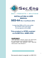
INSTALLATION & USER
MANUAL
SED-64 Rev 4 (software 021)
Incorporating GSM and 3G version guides
The wireless modem determines
If it can operate on 3G or GSM
This product is GPRS enabled
via SUREPOLL WIRELESS
WARNING
THIS SECURITY DEVICE MUST BE INSTALLED
BY A QUALIFIED & AUTHORIZED PERSON.
PLEASE READ THIS MANUAL FULLY BEFORE
INSTALLING THIS PRODUCT.
1
This manual is subject to copyright rev 2009.12.10
Warranty and Liability
WARNING
1/ The SED-64 is only to be installed by an authorised service
person.
2/ The supplied 16VAC Plug Pack must only be connected to a
AC 240v outlet socket with a protective earth connection.
3/ Ensure that the antenna is covered in 20mm conduit, when
installing in exposed places.
4/ Ensure the unit is mounted in a safe, secure & UPRIGHT
position.
The above points should be taken seriously. Failing to
abide by the above points, may result in the product not
performing as designed.
PRODUCT WARRANTY
This product is covered by a 12 month, Back-to-Base Warranty, from the
date of purchase, and proof of purchase should be supplied. The warranty
does not cover damage that has resulted in the improper installation or use of
the product. The warranty does not cover damage by lightning, product
misuse, electrical surges or acts of god.
LIMITATION OF LIABILITY
Sec-Eng Systems’ products are intended to reduce the risk of loss and
damage to property in which the goods are installed to the extent which is
practical. Sec-Eng Systems does not accept any liability for the loss or
damage to property or persons in relation to goods supplied. This disclaimer is
only limited to the warranty of the goods supplied and the intended use of the
goods.
2
TABLE OF CONTENTS
Section 1 - BASIC SETUP
1.1
1.1A
1.2
1.3
1.4
1.5
Installation Overview Diagram option systems
SED-64 system board guide
SIM Card Installation
Wiring and Terminations
Indication Lights
Operating Modes & Programming
Section 2 - INTELLIGENT SETUP
2.1
2.2
2.3
2.4
2.5
2.6
2.7
2.8
2.9
2.10
2.11
Manual Programming Mode
SMS Programming Mode
Programming Functions Summary
Program functions 1-6
Program functions 7-11
Program functions 12-16
Program functions 17-25
SMS reports
SMS commands
Control Room report codes
Reserved
Section 3 - GPRS SET UP
3.1
3.2
Enabling GPRS
Operational mode in GPRS
Section 4 - TESTING AND HELP
4.1
4.2
4.3
4.3
SED-64 Testing and Commissioning
Fault Guide
GPRS Testing
Technical Support
Section 5 – 3G BAND SELECTION
5.1
3G band selection guide
Section 6 – SED-64 BOARD OPTIONS
6.1
6.2
6.3
6.4
SED-64 Board option systems dual serial
SED-64 Board options systems single serial
SED-64 Board option systems 4 way I / O
SED-64 Board option systems (Mode 3 board)
3
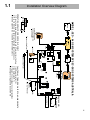
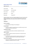
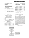
Installation Overview Diagram
Telecom
Line
4
3
Mode 3
T-Socket
STD DTMF PHONE
FOR PROGRAMMING
( OPTIONAL )
RJ 6p4c
RJ 6p4c
AC
12v
Battery
STATUS
WAKE
SED-64
Line Fail LED
Panel
plug
volts
Earth 16vac +Batt -
240Vac Plug Pac
To zone on Alarm Panel
Alarm Panel
serial
NC C NO
FAULT
C
5
4
3
2
1
SIGNAL
0
9
4
PWR
OH
8 ZONE FAULT
7
LOW BATT
FLT
6
STATUS
2 C 3
1
ZONE INPUTS
10K EOL
sim card holder
prog
PROG
TEST
N.C
NOTE : ALL 24 HR Multi break
Angle on sim
to be as shown
sim card
Expander Board
Port (optional)
FAULT RELAY TRIGGERS ON THE FOLLOWING EVENTS
1/ AC Power fail after 1 hr
2/ Low battery @10.7v
3/ Telecom line no voltage / no current @ 30sec
4/ Gsm signal or registration loss after 8 min
Wire to additional tamper button
installed on Alarm Panel
Volts
MODEL : SED - 64 GSM SYSTEM BY SEC-ENG SYSTEMS AUSTRALIA
AC
12v dc in
OPERATING SED-64 FROM SOURCE 12v DC ONLY
1/ Place 1 amp diode between one side of AC Terminal & + of battery
2/ Run 12v DC now into battery terminal (AC light should be on)
3/ Enable option 48 to a 1 ( disable dynamic battery test )
Earth 16vac +Batt -
PSTN Con 1
1.1
4
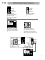
1.1a
NO
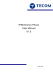
SED-64 Board option systems
1
2
Single
Relay
Board l
NC C
Dual
serial
Interface
led
RS232
Part :Sed 64 SRB
Control via sms
Part :Sed 64 DSI
Port 1 used to program
Sed 64 via serial
Port 2 used for upload
Down load
Inputs x 4
Phone
Panel
LD2
Outputs x 4
Part :Sed 64 4 way I/O
Extra 4 relays and inputs
that can be multi chained
SED 64 -mode3
LD1
Sed 64
4way I /O
Part :Sed 64 Mode 3
Used for GPRS systems
whereby you need a phone
line as a back up+gprs full time
STATUS
serial
prog
sim card holder
PSTN Con 1
Line Fail LED
Panel
LD2
SED 64 -mode3
Phone
NC C
LD1
led
1
2
5
4
3
2
1
SIGNAL
AC
SED-64
Single
Relay
Board l
RS232
volts
Earth 16vac +Batt -
NO
WAKE
Volts
NC C NO
FAULT
C
0
9
8
7
6
PWR
OH
ZONE FAULT
LOW BATT
FLT
STATUS
1
2 C 3
ZONE INPUTS
TEST
PROG
4
Part :Sed 64 4 way I/O
Inputs x 4
Sed 64
4way I /O
Outputs x 4
5
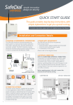
SIM Card Installation
1.2
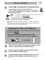
Check SIM card Operation in Mobile phone
1
Place the SIM card into any Standard GSM phone.
Telstra , Optus ,Vodafone Cards will work. “3” (Hutchison)
network WILL NOT WORK as it is a 3G ONLY network that
does not support GSM.
If the phone requests you to enter a pin number then
the SIM card is PIN LOCKED
SIMM CARD
NOTE:
The SIM card PIN request must be disabled
before it can be used in the SED-64
Warning: Ensure you have the correct pin number. Entering the
wrong PIN will PUK lock the SIM which will then need to be
returned to the vendor for reprogramming.
Disabling the PIN on the SIM card
To disable the PIN go to the mobile phone security menu
and select PIN OFF
Once done re-test by turning the phone OFF
then ON. The pin code should not be requested.
SIMM CARD
Unlocked
2
Ensure that the SIM Card does work and that a call
can be conducted from the Mobile Phone.
3
Test for signal strength (min 3 bars) at the alarm
location with the mobile phone.
4
Install the SIM card in the SED-64 as shown in the
Installation (Is the SIM in the right side up) see
1.1
6
1.3
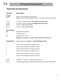
Wiring and Terminations
Terminal Connections
Terminal
Description
POWER
Earth
Connect to mains earth via plug pack
Note: remove solder tinning on earth wire, if provided, before connecting.
16 vac
AC input 16v AC plug pack ( As supplied with unit only )
16 vac
AC input 16v AC plug pack ( As supplied with unit only )
BATT +
12v DC battery input Positive
BATT -
12v DC battery input Negative
FAULT RELAY
NC
normally closed contact
C
common contact
N0
normally open contact
Warning: fault relay is at TNV-3 and is rated 0.5 A at 125 vac
ZONE INPUTS
(24hr Multibreak) 10k E.O.L. ( MUST BE INSTALLED )
C
Common for Zones Inputs ( negative float )
4
10k end of line resistor required to common
3
10k end of line resistor required to common
C
Common for Zone Inputs ( negative float )
2
10k end of line resistor required to common
1
10k end of line resistor required to common
PSTN
To Mode 3 T-Socket ( to panel and phone line )
CON 1
Used for programming via telephone handset and for audio across GSM
7
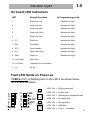
1.4
Indication Lights
On board LED Indications
LED
Normal Operation
In Programming mode
1
Signal level Low
Indicates the digit 1
2
Signal level Min
Indicates the digit 2
3
Signal level Med
Indicates the digit 3
4
Signal level Good
Indicates the digit 4
5
Signal level Best
Indicates the digit 5
6
FLT
GSM Fault
Indicates the digit 6
7
BAT
Low Battery
Indicates the digit 7
8
ZFLT
Zone unsealed
Indicates the digit 8
9
OH
GSM Transmitting
Indicates the digit 9
0
PWR
Power On
Indicates the digit 0
13 Fault Relay
Fault Relay
14 Line Fault
Telephone line not detected
15
AC OK
AC
Fault LED Guide on Power up
If LED 6 (FLT) is flashing refer to the LED’s as shown below
for the fault indication.
LED1 ON = GSM modem fault
PWR
5
4
3
2
1
0
9
8
7
6
SIGNAL
STATUS
TEST
LED2 ON = No Sim Card
OH
LED3 ON = GSM signal or registration fault
ZONE FAULT
LOW BATT
LED4 ON = Not Applicable
FLT
PROG
LED5 ON = Not applicable
LED6 ON = GSM fault
LED8 ON = Zone 1 - 4 unsealed
8
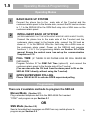
1.5
Operating Modes & Programming
Operating Modes
1
2
BASIC BACK UP SYSTEM
Connect the phone line to the male side of the T-socket and the
customers alarm panel to the female side ,connect the RJ lead as shown
in 1.1 to the SED-64 Wire the GSM fault relay into a 24Hr zone on the
customers alarm panel.
INTELLIGENT BACK UP SYSTEM
(WE RECOMMENDED THAT THE INTELLIGENT MODE BE USED IN MOST CASES)
Connect the phone line to the male side of the T-socket and the
customers alarm panel to the female side, connect the RJ lead as
shown in 1.1 to the SED-64. Wire the fault relay into a 24Hr zone on
the customers alarm panel. Power up the SED-64 and program
functions 1, 2 & 3. For programming details see Section 2.0 of this
manual Ensure the control room has set up the communication
Template on 2.10
3
FULL TIME (IF THERE IS NO PHONE LINE OR WILL NEVER BE
4
GPRS SUPERVISED POLLING
INSTALLED)
Program Function 07 for GSM Full Time (option=0) and connect the
customers alarm panel to the female side of the T-socket.
(You can also wire the RJ lead from the alarm panel to RJ on the
SED-64 CON1 directly without using the T-socket)
Phone 1300 65 44 33 to activate GPRS supervised polling
.
Programming
There are 2 available methods to program the SED-64
Manual Mode (Section 2.1)
Plug a standard telephone butt into the SED-62/64 Port marked
“CON1” and program as per Section 2.1
OR
SMS Mode (Section 2.2)
Send a formatted text messages via SMS from any mobile phone to
program as per Section 2.2.
9
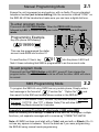
2.1
Manual Programming Mode
Ensure the unit is powered up and working with no faults. Plug any standard
telephone handset (set to tone dialling) into the connector marked “CON1” on
the SED-64 Lift the handset and make sure you can hear a digital dial tone.
To enter program mode
Press and hold the PROG Button. When the PROG LED illuminates
followed by LED 1, release the program button. You are now in Program
mode.
Programming Example
Key into phone the following:
019999
PWR
5
4
3
2
1
0
9
8
7
6
SIGNAL
STATUS
TEST
OH
ZONE FAULT
LOW BATT
FLT
PROG
Prog
LED
LED 1
This now has programmed the dialler
account code 9999 into function 01
Prog
Button
01
To read function 01 back, key
into the phone. LED 9 will
flash 4 times indicating that 9999 is programmed in as the account code.
To exit program mode
Press and hold the PROG Button until LED 1 goes off, then release the
program button. The PROG LED should be off and the other LEDS will return
to normal.
SMS Programming Mode
2.2
To program the SED-64 using SMS from any mobile phone, Simply write a
text message in the format of
“Function No” “Option No”
and
then send it to the SIM card mobile phone number in the SED-64
Attention : If the Master Code ( function 19) has been enabled, you must
first send *19????# (the ???? = Master Code) This will allow SMS
Programming Mode access for 5 minutes.
Example to program Function 01 client code = 9999 using SMS
Send the following text message * 019999 # to the SED-64 To program multiple
functions, just separate messages with a comma eg *01999#,*02134673#
Note: All SMS functions must start with a *(star) and end with a #(hash). Do 10
not use any spaces in between. This is the same as if you were programming
the SED-64 using manual mode programming.
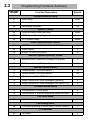
2.3
Programming Functions Summary
Function
Number
Function Description
Default
Communications setup
01
Client code
0000
02
Primary Receiver
nil
03
Secondary Receiver
nil
System Timers
04
GSM on-board dialer test time
24hrs
05
GSM signal fail relay trigger time
8min
06
PSTN alarm delay
30sec
GSM Communication modes
07
GSM Back Up / GSM FT / GSM FT PSTN Backup
1
08
PABX mode
0
09
Zones 1-4 lock out control
0
Ademco system reporting codes
10
Ademco event codes of on-board GSM dialer
11
Software Version (Read only)
0
n/a
SMS set up and control
12
Mobile phone 1 for SMS alarms
nil
13
Mobile phone 2 for SMS alarms
nil
14
Mobile phone 3 for SMS alarms
nil
15
Report options for SMS messages (general)
0
16
Report options for SMS messages (for zones 1-4)
0
On-board zones set-up
17
Configuration of zone types
0
18
Confirmation of arming /disarming zones via SMS
0
PIN Code Setup
19
Master Code
nil
Fault Relay setup
24
Functions & setting of Fault Relay Control (relay 0)
0
I/O Expander
25
Not used
11
0
Programming Functions Summary
Function
Number
2.3 cont
Function Description
Default
System features
26
Restricted access setting sms control number set
27
Setting of Group area from sms control phone 1
28
Setting of Group area from sms control phone 2
29
Setting of Group area from sms control phone 3
30
GSM switch number number
nil
31
GSM switch number delay
nil
32
Internal CID RX kiss off time adj 1-9 seconds
2
33
Digital volume adj for RX level 1-9
5
34
Digital volume adj for TX level 1-9
5
35
NA
nil
36
NA
nil
37
NA
nil
38
Input 1-4 bounce delay in 20ms blocks
5
39
NA
nil
40
NA
41
CID event code = 140 for alarms In1-4
140
42
Voice call duration limit
4min
43
Input termination 0=term 1=digital N.o 2=digital N.c
44
3G / Band Selection guide
127
45
3G READ ONLY BAND SELECTION GUIDE
R/O
46
NA
47
NA
48
Dynamic battery test disable ( dc systems only )
nil
0
0
12
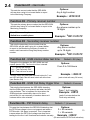
2.4
Function 01 - client code
Options:
Any 4 digit number
This sets the account code that the SED-62/64
will use when using its’ on-board dialler to report
to the Monitoring Company.
Example : *019999#
Function 02 - Primary receiver number
This sets the primary phone number that the SED 62/64
will dial when using its’ on-board dialler to report to the
Monitoring Company.
Note: Make sure the phone number can be
dialled from a mobile phone
Options:
Any phone number up to
18 digits
Example : *021234567#
Function 03 - Secondary receiver number
This sets the secondary phone number that the
SED 62/64 will dial when using its’ on-board dialler
to report to the Monitoring Company if unable to
make a valid connection using the primary receiver
number.
Options:
Any phone number
up to 18 digits
Example : *031234567#
Function 04 - GSM internal dialer test time
Change the time between the SED 62/64 test call
reports (sector 253). The time is in Hour intervals.
0 = No test call reports
24 = Test Call every DAY
168 = Test call once a week
To force a test call press and hold test button for 7 sec
test LED will flash, this will send a test call at the time
(see Section 2.8)
Options:
From 0 to 168 Hours
Example : *0424#
(sets a test call every 24 hours)
Function 05 - GSM Fail Relay trigger time
This sets the time between the SED-62/64 detecting
that the GSM signal is not present and when the fault
relay activates. This is important for times when the
GSM signal can occasionally drop out for short
periods but it is not necessary to send an alarm as it
restores within a few minutes.
Function 06 - PSTN Alarm delay
Default = 24 (Daily)
Default = 8 minutes
Options:
From 1 to 8 minutes
Example : *055#
(waits 5 minutes before the
Fault relay activates)
Default = 1 (30 seconds)
Options:
This sets the time between the SED-62/64 detecting that
the PSTN line voltage is low or not present and when a
0 = 50 seconds
13
PSTN trouble / fail alarm is reported. This is important
1 = 30 seconds
in areas where the PSTN line voltage can drop due to
loading but the line is still functional and restores normally.
Example : 060#
(50 secs before PSTN Fault activation)
*
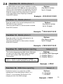
2.5
Function 07 - GSM Operation
Sets the way the SED-62/64 operates as a backup or other
modes.
GSM FT = GSM operates full time ( no phone line )
GSM BU = GSM operates as a back up unit
GSM FT / PSTN BU = GSM is used full time but will switchto
PSTN line if the GSM fails.
This
requires a dedicated PSTN line
Default = 1
Options:
0 = GSM FT= No phone line
1 = GSM BU ( default )
2 = GSM FT / PSTN BU
Example : *071#
Function 08 - PABX mode
If the Alarm Panel PSTN line is connected through a
PABX then the receiver phone number will have an
outside line number as a prefix (usually 0). In PABX
mode the SED-62/64 will ignore this first digit when it
dials out on the GSM network as it is not required.
Default = 0
Options:
0 = Dial all numbers
1 = Ignore the 1st Digit
Example : *080#
Function 09 - Zone 1 – 4 lock out control
This function provides a lockout feature on the 4 SED-62/64
zone inputs. Enable this to block reporting of rapid multiple
activations on a zone input.
Default = 0
Options:
0 = No Lockout
1 = Enter in minutes ( 1-30 )
Example : *091#
Function 10 - Ademco event codes
Sets the starting number for the SED 62/64 onboard dialler
reporting codes. In most cases , reporting codes 250 and
above are OK to use as the alarm panel does not need this
many codes but in larger systems where code 250 is in use,
the report codes for the SED 62/64 can be changed to 450
and above. Also Option 2 allows for ademco standard event
codes for power fail, low batt, PSTN Fail and GSM Test.
Refer to Section 2.10 for at list of report codes and event
codes.
Default = 0
Options:
0 = Starting at 250 ( default )
1 = Starting at 450
2 = Standard Event Codes
Example : *100#
Function 11 - Software Version
Displays the software version of the SED 62/64
program code. The read-back will be a 2 digit number.
No Options
(Read-back only)
Example : *11#
14
2.6
Function 12 - Mobile phone 1
The SED 62/64 can report events via SMS to 3 mobile
phones (see section 2.8) Note: we only recommend this
option for non-critical alarms or for secondary monitoring
purposes due to the nature of the SMS delivery service.
Enter the number of the first mobile phone to report to.
If left empty Mobile Phone Reporting is disabled.
Send 0000 to default
Options:
Any phone number
Up to 18 digits
Example : *120406991992#
Function 13 - Mobile phone 2
Enter the number of the second mobile phone for the
SED 62/64 to report events to.
Leave this option blank if no second mobile is needed
Send 0000 to default
Options:
Any phone number
Up to 18 digits
Example : *130406991993#
Function 14 - Mobile phone 3
Enter the number of the third mobile phone for the
SED 62/64 to report events to.
Leave this option blank if no third mobile is. Needed
Send 0000 to default
Options:
Any phone number
Up to 18 digits
Example : *140406991994#
Function 15 - SMS System reporting
This function determines what SMS System Messages
are sent by the SED 62/64. SMS System messages
are AC Fail, Low Batt, GSM Test and Fail to
Communicate.
Default = 0
Options:
0 = Disable SMS Messages
1 = Enable Option 1
2 = Enable Option 2
Option 1 = Sends All System Messages to Mobiles
Option 2 = Send all system Messages except GSM Test
Example : *150#
Function 16 - SMS Zone reporting
Enable this function if you would like an SMS
message sent to the mobile phone number,1,2,3
if Zones 1- 4 are activated. See Section 2.9 for
changing the text of the SMS message.
Default = 0
Options:
0 = Disabled
1 = Enabled
Example : *160#
15
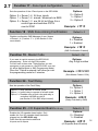
2.7
Function 17 - Zone Input configuration
Default = 0
Sets the operation of the 4 Zone Inputs on the SED-62/64
Options:
0 = Option 0
1 = Option 1
2 = Option 2
Option 0 = Zones 1-4 24 hour inputs
Option 1 = Zones 1-4 armed / disarmed via SMS
Option 2 = Zones 1-3 are 24 Hr but Zone 4 is a
control type and switches PSTN
over to GSM
Example : *171#
Function 18 - SMS Zone Arming Confirmation
Enables confirmation SMS Message of arm / disarm
of Zones 1- 4 (Function 17 = 1) See Section 2.9 for
more details
Default = 0
Options:
0 = Disabled
1 = Enabled
Example : *181#
(SMS Confirmation Enabled)
Function 19 - Master Code
Default = Nil
If you want to restrict access to the SED-62/64
programming. Enter a 4 digit PIN number.
You will have to then enter *19pin# before you can
reprogram or gain access to the SED-62/64 once set
(by either Manual Mode or SMS Programming Mode)
Options:
Any 4 digit number
Once the *19pin# is entered it will allow you into
the programming mode for 5 minutes.
Example : *191234#
(Sets Master Code to 1234)
Function 24 - Fault Relay
Default = 0
Options:
0 = Option 0
1 = Option 1
2 = Option 2
Sets the operation of the Fault Relay
Option 0 = relay operates in normal mode
Option 1 = Inverts relay to operate in fail safe mode
Option 2 = Disables relay as fault relay and relay is
controlled via SMS as relay 0.
(see Section 2.9 for SMS output control)
Example : *242#
(Relay controlled by SMS)
Function 25 – I/O Expander Board 61 62 only
Enables the I/O expander board option. Only
enable this if an I/O expander board has been
plugged into the SED 61/62 only
Once fitted this provided a additional
4 inputs and 4 outputs
Default = 0
Options:
0 = Disabled
1 = Enabled
Example : *251#
(I/O Expander Board Enabled)
16
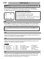
2.8
SMS Reports
NOTE: SMS commands must be as shown. (MUST BE IN CAPITALS)
From any GSM mobile phone, Simply send an SMS text message as
shown below to the SED-64 mobile phone number and it will send back
an SMS message with the requested report information.
Available SED 62 SMS reports
Abc
158
?P = Request SED-64 program setup
?S = Request SED-64 current status
?H = Request History - Displays the last 20 events
?T= Force test call now to control room
?P
Options
Back
?S
Send a ?S to request the current status of the SED-64. The current status
for the AC power, PSTN, Battery and GSM Signal Strength will be shown.
NOTE: If a Master Code has been set in the SED-64, you will not get a response from
any command (except for ?S). See Function 19 for information on the Master Code
setup.
?P
Send a ?P to request the current program function settings. See Section 2.3
for the list of function numbers and options.
?H
Send a ?H to request a list of the last 20 events that have occurred on the
SED-64. The first event listed is the oldest .
LEGEND
DT =
LB =
PF =
SF =
LF =
GSM Dialer test
Low battery
AC Power fail
GSM signal fail
PSTN line fail
i1 =
i2 =
i3 =
i4 =
DF =
input 1
input 2
input 3
input 4
Dialer fail
TO = timed out
PB = program via button
PS = program via sms
iD = inputs disarm
iA = inputs armed
BF= battery fail
Gf = GSM fail
Ipr = fail ip address
?BT= boot
MCF = modem fail
?T
When a ?T is sent to the SED-64 it will force a test call to the control room
and will reset the Test Call timer to start from this time. This can also be
done by holding the test button down for 10 seconds
17
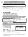
2.9
SMS Commands
The following SMS commands control additional features of the SED 62/64
NOTE: SMS commands must be as shown. (MUST BE IN CAPITALS)
Zone Arm and Disarm feature
The SED 62/64 Zone Inputs can be armed or disarmed by sending the
following SMS Text Message. This command will arm/disarm all Zone Inputs.
Important: It is advisable to program functions 16,17 & 18 to Option 1, and
program the mobile numbers into function 12, 13 & 14 if necessary.
Arm / Disarm Commands
?ON = Arms all 4 zones
(must be in capitals)
?OFF = Disarms all 4 zones (must be in capitals)
Zone Inputs Individual Text Labels
The SED 62/64 Zone Inputs can be programmed with individual text labels
for SMS reporting.
Parameter Description:
Text Message Format
<State> = “a” for alarm and “r” for restore
<Input> = Zone Input Number
in<State><Input><Text>
<Text> = Max 10 Characters (including
To Clear: send without <Text>
spaces)
Example:
ina1front door will program Zone 1 alarm with “front door alarm” (MAX 10 CHAR)
Relay Control
To control the SED 62/64 Output Relays, send an SMS message as follows:
Text Message Format
out<Relay>on {Timer}
out<Relay>off {Timer}
Example (for Relay 5)
out5on
out5off
out5on2
out5off2
Parameter Description:
<Relay> = Relay Number
{Timer} = Optional timer value
in Hours [h] minutes [m] and
seconds
= Turns Relay 5 on (indefinitely)
= Turns Relay 5 off (indefinitely)
= Turns Relay 5 on for 2 seconds (if relay is off)
= Turns relay 5 off for 30 seconds (if relay is on)
Note: Relays 1 - 4 are via an expander board, which must be enabled in programming (see
function 25). Relay 5 is onboard as standard and Relay 0 can be enabled if the fault relay is
not required (see function 24).
18
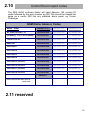
2.10
Control Room report codes
The SED 62/64 on-board dialler will send Ademco 140 contact ID
codes followed by the point number eg 250 This should be treated the
same as a sector 250 like any standard alarm panel. eg Tecom
Challenger
GSM Dialler Ademco Codes
Alarm event
Function 10 = 0
Function 10 = 1
Function 10 = 2
AC power fail after 1 hr
140 Sector 250
140 Sector 450
301 Sector 000
low battery < 10.7v or no battery
140 Sector 251
140 Sector 451
311 Sector 000
Telecom line fail
140 Sector 252
140 Sector 452
351 Sector 000
GSM test
140 Sector 253
140 Sector 453
602 Sector 000
Zone Input 1
140 Sector 254
140 Sector 454
140 Sector 001
Zone Input 2
140 Sector 255
140 Sector 455
140 Sector 002
Zone Input 3
140 Sector 256
140 Sector 456
140 Sector 003
Zone Input 4
140 Sector 257
140 Sector 457
140 Sector 004
Zone Input 5 (expander)
140 Sector 258
140 Sector 458
140 Sector 005
Zone Input 6 (expander)
140 Sector 259
140 Sector 459
140 Sector 006
Zone Input 7 (expander)
140 Sector 260
140 Sector 460
140 Sector 007
Zone Input 8 (expander)
140 Sector 261
140 Sector 461
140 Sector 008
DEFAULT
Note: restores are also sent for
each code
2.11 reserved
19
3.1
Enabling GPRS
1/. To enable the SED-64 for GPRS you must 1st have a SIM card that has
been supplied by Suretek. Phone Suretek on 1300 65 44 33 to obtain your
GPRS SIM card.
2/ Suretek will then program the SED-64 remotely for GPRS:
PWR
5
4
3
2
1
0
9
8
7
6
SIGNAL
STATUS
TEST
OH
ZONE FAULT
LOW BATT
FLT
PROG
The unit must be powered up and showing signal strength.
Suretek (Ph 1300 65 44 33) will then remotely program the SED-64 for GPRS
supervise polling.
Once this has been complete and is on line the OH light will flash every 3
seconds to indicate the unit is on line and polling, every 30 seconds the OH
led will flash for 5 seconds to poll the base end, it is now GPRS enabled.
3.2
Operational modes in GPRS (not available in 3G)
You can now operate the SED-64 in either mode 1 or mode 2
for GPRS
MODE 1 : The SED-64 will allow the alarm panel to dial out on the phone line
as
normal but will poll the SED-64 every 90 seconds on GPRS for system
integrity.
Any system alarms from the SED-64 will go via GPRS & in the event the
Phone Line is severed, all alarms from the panel will then go via the GSM
voice channel to Contact Id receiver.
MODE 2 : All alarms will be sent via GPRS. The alarm panel will dial out via
GPRS thru the SED-64. In the event the GPRS network is not available the
alarm will be sent via GSM. If there is no available GSM network signal, it will
revert to the phone line if present.
Note: For mode 2 operation, you are required to have a dedicated phone line.
NOTE: SEE TESTING GUIDE 4.3
20
4.1
Testing and Commissioning
Please perform the following tests after completing the installation
of the SED 62/64
Testing the SED-64 Basic GSM Backup
1. With the unit powered up and working (Status LED flashing and at least 3
bars of signal strength), disconnect the T-socket from incoming telecom line.
2. The unit will detect a line fault after a short period (Line Fail LED will
illuminate) and then, after the PSTN fail detect time 30 sec the fault relay will
activate (unless function 24 is not at the default). Also, if the SED-64 is in
intelligent mode, a PSTN line fail will be reported to the Alarm Company by
the SED 62/64
3. Now trigger an alarm on the customers alarm panel. As the alarm panel dials
out, it will communicate over the GSM network through the SED 62/64. On
the SED-64 the OH light (LED 9) will come on solid, indicating that the alarm
panel is communicating over the GSM network.
4. Once the Alarm Panel has successfully reported the alarm, it will hang up.
Check with the Monitoring Company that they received the correct alarm
report. If the alarm panel does not communicate successfully check Section
3.2 to diagnose the problem.
5. Once testing is complete, plug the telephone line back in to the T-socket.
The line fail LED should go out and after about 1 minute the fault relay will
de-activate.
Testing the SED-64 Intelligent GSM Backup
1. Make sure Functions 1, 2 & 3 on the SED-64 are programmed and that the
SED-64 is working (Status LED flashing and at least 3 bars of signal
strength).
2. Activate then re-seal Zone 1 on the SED-64.The OH light (LED9) will flash
while the SED-64’s internal dialler is dialling. The SED-64 will report Sector
254 to the monitoring company (this should take less than 10 seconds).
3. Disconnect the T-socket from incoming telecom line.
4. The line fail LED will illuminate and, after about 20 seconds, the OH light
(LED 9) will start flashing as the SED-64 reports a Sector 252 to the
monitoring Company. Once the OH light stops flashing the fault relay will
activate.
5. Now plug the T-socket back into phone line and the SED-64 will send a
PSTN restore through.
6. Check with the Monitoring Company that they received the correct alarm
reports. (Zone 1 set/restore and PSTN set/restore) If the alarm panel does
not communicate successfully check Section 3.2 to diagnose your problem. 21
4.2
Fault Guide
Before calling for support please look to see if your problem is listed below.
1. The Fault light is on or flashing
Remove the power from the SED-64, then remove the SIM card and put it in a working GSM
phone. Turn the GSM phone on. If the phone asks for a PIN number, the SIM card is pin code
locked. Go to phone set up / security settings and turn the PIN request off. Power off the phone
then on again. It should not ask for a PIN. Put the phone next to the SED 62/64 antenna
location and make sure you have at least 3 bars of signal on the GSM phone. Making sure the
power is still off on the SED 62/64, re-insert the SIM card and power it up. When the SED-64
finds signal, the wake LED should be on with the status LED flashing and the signal meter will
show signal.
2. I cannot program the SED-64
With the SED 62/64 powered up, put a standard PSTN phone into “CON1” on the SED 62/64
board. Press and hold the “PROG Button” until LED1 lights up, remove your finger immediately
from the button. The “PROG LED” should stay illuminated. First, do a LED Test by pressing the
* (Star key) on the phone, LEDs 1,3,5,6,8 & 0 should light. Now Press the # (hash key), the
LEDs 2,4,7 & 9 should light. If no LEDs light up, check that the phone you are using is set to
Tone (DTMF) dialling and not pulse (Decadic). If the LEDs do light up, do a read back of
function 01 by keying on the phone *01# The LEDs should illuminate in order of the client
code. If the unit has not been programmed before, the client code should be 0000. If no LEDs
illuminate then the SED 62/64 may have a Master Code (Function 19). You can now try
defaulting the SED-64 (but make sure you know all the program settings before doing this, as
you will need to re-program the SED62/64 from scratch!) Default the unit by being in program
mode and entering *996060# (for SED62) or *996464# (for SED-64). To check if it is defaulted
OK, do a read back of function 01 again. LED 0 should flash 4 times indicating an account
code of 0000.
3. I do not receive a response via SMS
Check that you have the correct mobile number for the SIM card in the SED 62/64. If it is
correct then the SED-62/64 may have MASTER CODE (Function 19) set. If you know the
Master Code try sending the following SMS *19????# (where ???? = Master Code). If it
correct the SED 62/64 will send back an SMS with “PIN OK” If you see this message then you
have 5 minutes to send the SED 62/64 SMS commands. If you still do not get a response then
a technician will probably need to visit the site.
4. The SED-64 on-board dialler is not communicating
Check to see if Functions 01, 02 & 03 are programmed correctly. When you trigger a Zone
Input on the SED 62/64, does the OH light flash? If OH (LED 9) is flashing, this is indicating that
the on-board dialler is working. If the OH LED is not flashing check that the zones are armed.
Put a phone into CON1 and when the OH LED is flashing, pick up the handset and listen in for
comms to the Control Room. If you hear comms check with the Control Room that they are
monitoring the correct Contact ID codes.
22
4.2 cont
Fault Guide cont..
6. I Programmed the SED-64 OK but the Alarm Panel will not
communicate with the Control Room via GSM
To test the GSM communications, plug a standard phone or phone Butt into “CON1” and
pickup the handset (off-hook the Butt), You should hear dial tone, this is generated by the
SED 62/64. If you do not hear a dial tone then make sure:
1/ The SED 62/64 is powered up
2/ You are definitely plugged into “CON1”
3/ The phone you are using is in good working order.
If you do hear dial tone, make a call to the control room using the same number that is
programmed into the Alarm Panel / SED 62/64. If you cannot get through, try calling your
mobile phone. If your mobile phone rings then the SED 62/64 is good, so check that the control
room number is correct.
If when you called the control room number you heard the Ademco BEEP BEEP, then the
control room number and the SED 62/64 are good and the problem is usually in the way the
Alarm Panel dialer communicates.
Firstly, check that the Alarm Panel and the SED 62/64 are using their respective separate plug
power packs. A single plug pack should not be used to power both units, make sure the
SED 62/64 is powered by the plug pack provided by Sec-Eng Systems. Next, with the butt still
plugged into “CON1”, unplug the t socket from the phone line, wait for line fail LED to activate
then, activate an input on the Alarm Panel. Listen in on the call while the Alarm Panel
communicates to the Control Room by picking up the butt when the OH (LED 9) is illuminated.
If you can hear the panel get through but the control room won’t kiss off (you will hear the
Panel retry 2 or more times) then it is probably necessary to adjust the Gain Control on the
SED 62/64. To adjust the gain, locate the pots marked “to” and “from” in the middle of the
SED 62/64 Board. Turn the “to” pot to fully clock wise and trigger an alarm on the alarm panel.
If it still does not make a successful report then turn the “from” pot to fully anti clockwise and
test again. If it is still not communicating then return the “to” pot to the middle and adjust the
“from” pot using the same procedure.
5. The Alarm Panel is working on GSM but Control Room is not
receiving the Alarms
Put a telephone or phone butt into “CON1” and listen to the Alarm Call by picking up the
handset when the OH (LED 9) is On. Do you hear a Kiss off signal after the panel has sent
through the Alarm information? If you do, but the control room says that they didn’t receive the
alarm, then the number may be re routed. Ask the control room for a non-1300 or another 1300
number to try.
23
4.3
GPRS Testing MODE 1
BASIC GPRS COMMS
1/ If the OH light is flashing every 3 seconds then rapidly every 40 seconds
you are polling on GPRS.
Call Suretek on 1300 65 44 33 to confirm the SED-64 is polling via GPRS.
TESTING ALARMS MODE 1
Trigger a zone on the SED-64 and check that the OH light starts to flash for
approximately 5 seconds, this confirms the SED-64 has sent zone alarm via
GPRS.
If you now disconnect the T piece socket from the phone line, it should after
30 seconds send a line fail thru via GPRS.
IF you now trigger the customers alarm panel it should send an alarm thru
via the normal Contact Id receiver via GSM and not via GPRS.
GPRS Testing MODE 2
BASIC GPRS COMMS
1/ If the OH light is flashing every 3 seconds, then rapidly every 40
seconds, you are Polling on GPRS.
Call Suretek on 1300 65 44 33 to confirm the SED-64 is polling via GPRS.
TESTING ALARMS mode 2
With GPRS MODE 2 all alarms are converted to data from Contact ID
With the T socket disconnected from the phone line, now trigger the
customers alarm panel. The OH light will light up and the panel will now
dial through the SED-64. If you plug a butt into CON1 you will be able to
hear the Contact ID conversion as the SED-64 is acting as a Contact ID
receiver.
Once converted to GPRS DATA the OH light will flash to indicate it is
sending the captured alarms via GPRS.
Check with your control room as the alarms should have gone through via
GPRS.
24
5.1
Function 44 - 3G next G Band selection guide
Default = 127
Setting the band selection for the 3G network
normally should not be touched as is automatic
Examples:
1
GSM850
2
EGSM 900
4
GSM1800
6
EGSM+GSM1800
8
GSM1900
9
GSM850+GSM1900
10
EGSM900+GSM1900
15
QUADBAND
16
3G 2100
32
3G 1900
64
3G 850
Example : *44127#
(Sets default)
25
6.1
SED-64 Board option - Dual Serial
Dual
serial
Interface
TECOM TS 0091
SERIAL / PRINTER
INTERFACE
1
2
RS232
Tx
Rx
Cts
Rts
Gnd
Port A
Port B
This interface is used to allow
serial comms for the SED-64
Port 1 is used so you can
program the SED-64 via
HyperTerminal @115k 8N1
Port 2 is used for up load down
load via a circuit switched data
connection on the SIM card
Program PC
INSTALLING THE BOARD / Fit onto the SED-64 board into the position shown
on page 1.1a into the top 10 way connector on the SED-64 marked SERIAL
PROGAMMING
Connect any laptop or PC using a straight thru serial connection onto Serial 1
On the SED-64 this allows for programming and set up for the SED-64
Connect using HyperTerminal at 115k 8 N 1 to Port 1
Hit enter and password shall appear now type zxcvbnm in lower case
You are now in the program mode Type ?S to see if you are in
SET UP PORT 2
With PC still connected, type the following:
CSDSPD=4800 (enter)
CSDRING=2
(enter)
CSDEN=1
(enter)
Now type ?CSDEN and the setting should be the same as you have just typed.
The SED-64 is now set up to receive circuit switched in-coming data calls
Wire up PORT 2 now to the TECOM TS 0091 as shown with lead provided
26
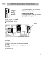
6.2
NO
SED-64 Board option - Single Relay
1/ To install this board, you will need an
SED-64 version 9 onwards
NC C
Single
Relay
Board l
led
POWER DOWN SED-64
2/ Remove mounting screw top RH-side
3/ install 10 mm hex stand off
4/ now fit board as shown
Part :Sed 64 SRB
Control via sms
Here
STATUS
serial
prog
sim card holder
PSTN Con 1
Line Fail LED
Phone
Panel
LD2
SED 64 -mode3
LD1
led
1
2
RS232
5
4
3
2
1
volts
SIGNAL
AC
Earth 16vac +Batt -
SED-64
NC C NO
WAKE
Volts
NC C NO
FAULT
C
0
9
8
7
6
PWR
OH
ZONE FAULT
LOW BATT
FLT
STATUS
1
2 C 3
ZONE INPUTS
TEST
PROG
4
Part :Sed 64 4 way I/O
TESTING
To Test this board, SMS the SED-64 the following
OUT1ON
This will now turn the relay on, see LED on the board
OUT1OFF
will now turn it off
27
6.3
SED-64 Board options - 4 way I/O
Inputs x 4
This board allows for
an extra 4 inputs and 4 outputs
operating from the SED-64 v009
onwards
Sed 64
4way I /O
Outputs x 4
Part :Sed 64 4 way I/O
Extra 4 relays and inputs
that can be multi chained
Part :SED 64 4-way I/O
INSTALLATION PROCESS
1/ Power down the SED-64
2/ Fit Card as shown
3/ Fit 4 X 10k EOL into Inputs
4/ Power up
5/ Dip switches
Inputs x 4
SED 64
4-way I /O
Outputs x 4
STATUS
serial
WAKE
prog
sim card holder
PSTN Con 1
Line Fail LED
1
2
10 WAY
RIBBON
LEAD
RS232
5
4
3
2
1
volts
SIGNAL
AC
Earth 16vac +Batt -
SED-64
Volts
NC C NO
FAULT
C
0
9
8
7
6
PWR
OH
ZONE FAULT
LOW BATT
FLT
STATUS
1
2 C 3
ZONE INPUTS
TEST
PROG
4
TESTING
The 4 zones can be tested thru and should come thru as zones
Point Number 258 to 261 see page 2.10 for details
Relays on this board are now controlled via SMS
Relay 1 = out5on
Relay 2 = out6on
Relay 3 = out7on
Relay 4 = out8on
See section 2.9 relay control for more functions
28
SED-64 Board option systems (Mode 3
board)
6.4
LD1
Panel
LD2
Mode 3 relay board is used for GPRS systems,
whereby you need the clients phone line returned
to the customer and the panel, thus working GPRS
full time
SED 64 -mode3
Phone
Here
STATUS
serial
prog
sim card holder
PSTN Con 1
Line Fail LED
Phone
Panel
LD2
SED 64 -mode3
LD1
led
1
2
RS232
5
4
3
2
1
volts
SIGNAL
AC
Earth 16vac +Batt -
SED-64
NC C NO
WAKE
NC C NO
FAULT
Volts
C
0
9
8
7
6
PWR
OH
ZONE FAULT
LOW BATT
FLT
STATUS
1
2 C 3
ZONE INPUTS
TEST
PROG
4
PSTN line in on pins 3 & 4.
Return line to Customer's Phone on pins 2 & 5.
Install as shown
STATUS
WAKE
PHONE
PANEL
LD2
SED 64 -mode3
use exsisting 5 m Rj lead to Rj
lead from instalation
4 wire
pins 3 & 4= pstn to panel
pins 2 & 5 = mode 3 return
PSTN Con 1
To Panel
LD1
gsm/gprs
module
batt Volts
AC
Earth 16vac +Batt -
Sed 64
Please refer to install guide supplied
29