1
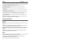
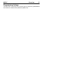
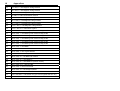
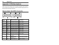
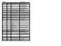
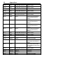
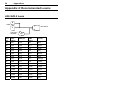
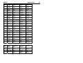
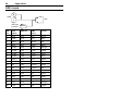
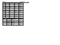
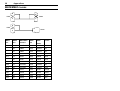
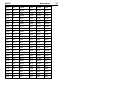
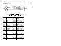
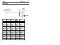
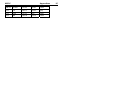
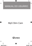
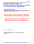
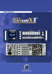
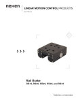
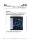
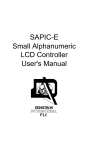
MoTeC SIM3 Manual SIM3 Engine Simulator User’s Manual Contents Introduction ........................................................................ 4 Overview ............................................................................. 5 Signal Outputs ....................................................................................................5 Analog Inputs ......................................................................................................5 Switch Inputs.......................................................................................................5 Speed Inputs.......................................................................................................5 Ref/Sync Inputs.................................................................................................10 Communications ...............................................................................................11 PC Communications .........................................................................................12 Miscellaneous ...................................................................................................12 Front Panel .......................................................................................................14 Appendix 1: Specifications............................................. 15 Environmental ...................................................................................................15 Electrical ...........................................................................................................15 Operation ..........................................................................................................15 Appendix 2: Ref/Sync Modes ......................................... 17 Appendix 3: PIN Descriptions ........................................ 20 Device Under Test (DUT) Connector ................................................................20 RS232 Connector (D9)......................................................................................23 Power Connector (3pin XLR Male)....................................................................23 CAN Connector (5pin XLR Female) ..................................................................23 Appendix 4: Recommended Looms .............................. 24 ADL/ADL2 Loom ...............................................................................................24 SDL Loom .........................................................................................................26 M800/M880 Looms ...........................................................................................28 M4/M48 Loom ...................................................................................................31 M8 Loom ...........................................................................................................33 Copyright 2005 – Motec Pty Ltd The information in this document is subject to change without notice. While every effort is taken to ensure correctness, no responsibility will be taken for the consequences of any inaccuracies or omissions in this manual. 11 July, 2005 4 Introduction Introduction This document describes the MoTeC SIM3 engine simulator. It is intended for use in conjunction with a MoTeC ECU or ADL to simulate signals from an engine and various sensors. This allows in depth testing of ECU/ADL configurations, functions and is also a valuable training aid. In order to simulate different triggering systems and modes, the SIM3 has the ability to generate a large number of Ref/Sync modes. See Appendix 2 for a full list of currently available Ref/Sync modes SIM3 Front Panel MoTeC Overview 5 Overview Note: The SIM3 I/O terminology and labelling always refers to the functionality of the attached Device Under Test (DUT), ie: the ECU or ADL. Signal Outputs There are 24 output test points and associated LED indicators for outputs from the DUT, grouped as INJECTOR, IGNITION and AUXILIARY OUTPUTS. The LED indicators are active when the associated DUT connector pin is pulled low by the DUT. The test points are connected directly to the associated DUT connector pin and may be used to attach external loads to outputs. Analog Inputs There are 8 potentiometers labelled AV1 to AV8 for analog inputs to the DUT. Each potentiometer varies the analogue voltage at the associated DUT connector pin and test point between 0V and 5V. The 5V is supplied by the DUT. The 0V and 5V must be supplied by the DUT on the 0V and 5V DUT connector pins in order to use the analog inputs. Switch Inputs The 4 SWITCH INPUT switches (on, off or momentary on) switch the DUT switch inputs to the 0V from the DUT. Speed Inputs The SPD1 to SPD4 potentiometers and the SPEED MODE rotary switch control the speed inputs to the DUT. The speed inputs are available on the DUT connector and on test points SPD1 to SPD4. Speed inputs on the DUT may also be known as Digital inputs. The functionality of the speed inputs is determined by the SPEED MODE switch as described below. The STATUS LED flashes if an invalid speed mode is selected. An invalid speed mode is a switch position that does not have a mode implemented. 6 Overview Speed Mode 0 SPD1 Pot Speed 1 input frequency SPD2 Pot Speed 2 input frequency SPD3 Pot Speed 3 input frequency SPD4 Pot Speed 4 input frequency Notes: Frequency is variable from approx 10Hz to 1200Hz Duty cycle is fixed at 50% At the minimum pot position (fully anticlockwise), the corresponding speed input is held high. This corresponds to a duty cycle of 0%, ie: speed = 0. Speed Mode 1 SPD1 Pot Speed 1 input frequency SPD2 Pot Speed 1 input duty cycle SPD3 Pot Speed 3 input frequency SPD4 Pot Speed 3 input duty cycle Notes: Frequency is variable from approx 10Hz to 1200Hz Duty cycle is variable from 0 to 100% Speed Mode 2 Notes: SPD1 Pot RPM divider ratio for Speed 1 input SPD2 Pot RPM divider ratio for Speed 2 input SPD3 Pot RPM divider ratio for Speed 3 input SPD4 Pot RPM divider ratio for Speed 4 input MoTeC Overview Speed inputs are variable with the speed pots and with RPM. The resulting frequency is variable up to approx 930Hz (at 20000RPM) Duty cycle is fixed at 50% At the minimum pot position (fully anticlockwise), the corresponding speed input is held high. This corresponds to a duty cycle of 0%, ie: speed = 0. Speed Mode 3 SPD1 Pot Speed 1 input on/off SPD2 Pot Speed 2 input on/off SPD3 Pot Speed 3 input on/off SPD4 Pot Speed 4 input on/off Notes: The pots now act as on/off switches and not as a variable speed signals. At the minimum pot position (fully anticlockwise), the corresponding speed input is held high. Otherwise the input is held low. Speed Mode 4 SPD1 Pot Speed 1 input frequency SPD2 Pot Speed 2 input frequency SPD3 Pot Speed 3 input frequency SPD4 Pot Speed 4 input frequency Notes: Frequency is variable from approx 0Hz to 100Hz Duty cycle is fixed at 50% At the minimum pot position (fully anticlockwise), the corresponding speed input is held high. This corresponds to a duty cycle of 0%, ie: speed = 0. 7 8 Overview Speed Mode B SPD1 Pot Sync advance/retard SPD2 Pot SPD3 Pot Cam 0 retard on Speed3 input SPD4 Pot Cam 1 retard on Speed4 input Notes: Sync signal is active depending on the ref/sync mode. Sync advance/retard range is set separately for each particular ref/sync mode. The maximum RPM that Sync and Cam control will reliably work at is dependent on the particular ref/sync mode. For example, with narrow sync pulses (positive going) of 3 degrees width, the advance/retard only works reliably to around 7000rpm. The cam retard range is set separately for each particular ref/sync mode. Speed Mode C SPD1 Pot Cam 0 retard on Speed1 input SPD2 Pot Cam 1 retard on Speed2 input SPD3 Pot Cam 0 retard on Speed3 input SPD4 Pot Cam 1 retard on Speed4 input Notes: Mode C allows four cam signals to be generated, with each cam waveform appearing on two speed outputs with individual retard control. Cam0/Cam1 refers to the source waveform. Cam signals are retarded from their position in the ref/sync data in flash. The maximum RPM that Cam control will reliably work at is dependent on the width of the cam pulses. The cam retard range is set separately for each particular ref/sync mode. Depending on the ref/sync mode, the retarded Cam 0 signal controlled by the SPD1 pot may also be used as the Sync signal. MoTeC Overview 9 Speed Mode D SPD1 Pot Cam 0 retard on Speed1 input SPD2 Pot Cam 1 retard on Speed2 input SPD3 Pot RPM divider ratio for Speed 3 input SPD4 Pot RPM divider ratio for Speed 4 input Notes: Cam signals are retarded from their position in the ref/sync data in flash. The maximum RPM that Cam control will reliably work at is dependent on the width of the cam pulses. The cam retard range is set separately for each particular ref/sync mode. Depending on the ref/sync mode, the retarded Cam 0 signal controlled by the SPD1 pot may also be used as the Sync signal. Speed inputs 3 & 4 are variable with the speed pots and with RPM. The resulting frequency on speed inputs 3 & 4 is variable up to approx 930Hz (at 20000RPM) Speed inputs 3 & 4 duty cycle is fixed at 50% At the minimum pot position (fully anticlockwise) for pots 3 & 4, the corresponding speed input is held high. This corresponds to a duty cycle of 0% Speed Mode E SPD1 Pot Cam 0 retard on Speed1 input SPD2 Pot Cam 1 retard on Speed2 input SPD3 Pot Speed 3 input frequency SPD4 Pot Speed 3 input duty cycle Notes: Cam signals are retarded from their position in the ref/sync data in flash. The maximum RPM that Cam control will reliably work at is dependent on the width of the cam pulses. The cam retard range is set separately for each particular ref/sync mode. 10 Overview Depending on the ref/sync mode, the retarded Cam 0 signal controlled by the SPD1 pot may also be used as the Sync signal. Speed 3 frequency is variable from approx 10Hz to 1200Hz Speed 3 duty cycle is variable from 0 to 100% Speed Mode F SPD1 Pot Cam 0 retard on Speed1 input SPD2 Pot Cam 1 retard on Speed2 input SPD3 Pot Speed 3 input frequency SPD4 Pot Speed 4 input frequency Notes: Cam signals are retarded from their position in the ref/sync data in flash. The maximum RPM that Cam control will reliably work at is dependent on the width of the cam pulses. The cam retard range is set separately for each particular ref/sync mode. Depending on the ref/sync mode, the retarded Cam 0 signal controlled by the SPD1 pot may also be used as the Sync signal. Speed 3 and Speed 4 frequency is variable from approx 10Hz to 1200Hz Speed 3 and Speed 4 duty cycle is fixed at 50% At the minimum pot position (fully anticlockwise) for pots 3 & 4, the corresponding speed input is held high Ref/Sync Inputs The ref/sync generator can generate different ref, sync and cam signals for input into an ECU. Up to 256 ref/sync modes can be stored in the onboard SIM3 FLASH memory. These ref/sync modes can be upgraded from a PC over the CAN bus. The ref/sync generator has test points for REF, SYNC, TDC and TRIGGER signals. Cam signals are generated using the relevant CAM related speed modes. MoTeC Overview 11 The ref/sync mode is selected with the two REF/SYNC MODE rotary switches. If the SIM3 PC application is running, a brief description of the current mode is retrieved from the SIM3 and displayed on the PC. The COARSE and FINE RPM rotary pots can adjust the RPM up to approximately 20000rpm. The ref and sync input waveforms can have both positive and negative components. The REF RISE/FALL and SYNC RISE/FALL switches determine the polarity of the ref and sync input waveforms. The REF MAG/HALL and SYNC MAG/HALL switches remove the negative component of the ref or sync waveforms when in the HALL position. The REF LEVEL and SYNC LEVEL pots determine the amplitude of the ref and sync waveforms. The OFFSET pot determines the DC voltage offset of both the ref and sync waveforms. The offset can be positive or negative. Communications RS232 The DUT connector has logic level and RS232 level pins for serial connection to the DUT. Only one of the serial interfaces should be used at a time, as both interfaces connect to the single 9 pin RS232 connector on the SIM3. The logic level interface has an RS232 level shifter in the SIM3, allowing an M4/M48/M8 ECU to be connected to a PC without needing a PCI cable or CIM module. The RX and TX test points are connected directly to the RS232 level pins (RX232 and TX232) on the DUT connector. CAN The CAN pins on the DUT connector are connected directly to the CAN-HI and CAN-LO test points, and to the 5 pin CAN connector. The microcontroller in the SIM3 is also connected to the CAN bus for communication with the SIM3 PC application. There are no CAN termination resistors in the SIM3. 12 Overview USB For USB connection to the ADL2 or SDL, the SIM3 loom should provide a USB type B socket that is wired directly to the DUT. There is no USB connection available via the SIM3. Note that a UTC can be plugged directly into the SIM3. PC Communications The SIMSEND PC application is used to send ref/sync patterns to the SIM3, and to view the description of the currently selected ref/sync mode. To install Simsend, create the folder c:\motec\sim3 and copy simsend.exe and sim3.bin into the folder. CAN drivers must be installed on the PC (by installing another MoTeC product) to use Simsend. Sim3.bin contains the ref/sync modes. The current ref/sync modes are described in Appendix 2. An editor is currently planned to allow the refsync modes to be modified. To send ref/sync modes to the SIM3, connect the CAN cable to the SIM3 then run simsend.exe and press the Start button. It will then take a few minutes to send the file. The Simsend application displays information about the currently selected ref/sync mode. Note that if the selected ref/sync mode is empty, the ref/Sync description will display rubbish. The Simsend application cannot be run in conjunction with other PC applications (such as ECU manager) that use the CAN bus to communicate with the DUT. Miscellaneous Voltage Test Points The ECU 8V, 5V and 0V test points are connected directly to the 8V, 5V and 0V connector pins to test the DUT voltages. The BATT- and BATT+ pins are connected directly to the SIM3 power supply after the main power switch and fuse. MoTeC Overview 13 Programming Voltage The VPP switch controls the VPP connector pin for programming M4/M48/M48 units without an external SUU (Software Update Unit). 14 Overview Front Panel MoTeC Appendices 15 Appendix 1: Specifications Environmental Dimensions (mm): 190 (w) x 138 (h) x 46 (d) Ambient temperature range: -10°C to 70°C Weight: 500g Electrical Input Supply Voltage: 8V – 15V Reverse Voltage Protection Battery Transient Protection Maximum Current: 0.5A (excluding external device) Internal 10A fuse Operation Hardware • 8 x analogue outputs with potentiometers and test points for measuring the voltage • 4 x switches (on/off/momentary) • 4x speed outputs with several modes of operation, including CAM position simulation • 24 x test points for device outputs (8 x IGN, 8 x FUEL, 8 x AUX) with LED indicators • Test points for ECU 0V, 5V, 8V • RPM generation to 20000 RPM • REF/SYNC generator with REF, SYNC, TDC and TRIGGER outputs and REF/SYNC LEDs • REF/SYNC modes allow edges to be defined with 0.5 degree resolution • HALL and MAG ref/sync generation with adjustable levels and polarity 16 Appendices • Provision for up to 256 REF/SYNC modes, each with up to two CAM position waveforms • CAN communication via 5pin “canon” socket for CAN cable • Power via 3 pin “canon” socket • M4/M48/M8 ECUs can be connected via the simulator to a PC without a PCI cable (standard RS232 cable) • Allows M4/M48/M8 ECU programming without external SUU • Connector Type: 60 way (same as M800) Software • Field update of REF/SYNC generator software via CAN • SPEED status LED flashes when setup in an invalid mode or a pot that isn’t in use, is moved • REF LED flashes if an invalid REF/SYNC mode is selected, ie: a mode number that does not have a mode implemented for it. • Status information available via CAN includes – REF/SYNC mode, RPM, SPEED mode, SPEED output frequency/duty cycle or CAM retard in degrees MoTeC Appendices 17 Appendix 2: Ref/Sync Modes The following list contains the default ref/sync modes supplied with the SIM3. The description is crank (sync) teeth / crank degrees, cam (ref) teeth / crank degrees. Eg: 6/360, 1/720 indicates that there are 6 crank teeth and 1 tooth on the camshaft. Hall modes transition between two voltage levels, while Magnetic modes have three voltage levels. The amplitude of the signal can be adjusted with the ‘Level’ control, while a DC offset (not normally required) can be added using the ‘Offset’ control. Mode Description 00 2 / 360, 1 / 720 Hall Dual Edge & 1 Tooth 01 3 / 360, 1 / 720 Hall Dual Edge & 1 Tooth 02 4 / 360, 1 / 720 Hall Dual Edge & 1 Tooth 03 5 / 360, 1 / 720 Hall Dual Edge & 1 Tooth 04 6 / 360, 1 / 720 Hall Dual Edge & 1 Tooth 05 12 / 360, 1 / 720 Hall Dual Edge & 1 Tooth 0A 2 / 360, 2 / 720 MX5,VR4 etc 0B 3 / 360, 4 / 720 0C 12 / 360, 1 / 720 Commodore series III 0F 1 / 360, 2 / 720 Harley Davidson 10 2 / 360, 1 / 720 Magnetic 6 Deg Duration 11 3 / 360, 1 / 720 Magnetic 6 Deg Duration 12 4 / 360, 1 / 720 Magnetic 6 Deg Duration 13 5 / 360, 1 / 720 Magnetic 6 Deg Duration 14 6 / 360, 1 / 720 Magnetic 6 Deg Duration 15 8 / 360, 1 / 720 Magnetic 6 Deg Duration 16 10 / 360, 1 / 720 Magnetic 6 Deg Duration 17 12 / 360, 1 / 720 Magnetic 6 Deg Duration 18 Appendices 18 18 / 360, 1 / 720 Magnetic 6 Deg Duration 19 20 / 360, 1 / 720 Magnetic 6 Deg Duration 1A 16 / 360, 1 / 720 Magnetic 6 Deg Duration 1F 4 / 360, 2 / 720 Ford Cosworth /Lancia 20 4+1 / 360, 1 / 720 Magnetic 6 Deg Duration 21 6+1 / 360, 1 / 720 Magnetic 6 Deg Duration 22 8+1 / 360, 1 / 720 Magnetic 6 Deg Duration 23 12+1 / 360, 1 / 720 Magnetic 6 Deg Duration 2A 12+1 / 360, 4+1 / 720 Honda Type R 30 30-1 / 360, 1 / 720 Missing tooth mode for Mag & Hall 31 30-2 / 360, 1 / 720 Missing tooth mode for Mag & Hall 32 36-1 / 360, 1 / 720 Missing tooth mode for Mag & Hall 33 36-2 / 360, 1 / 720 Missing tooth mode for Mag & Hall 34 60-2 / 360, 1 / 720 Missing tooth mode for Mag & Hall 35 66-1 / 360, 1 / 720 Missing tooth mode for Mag & Hall 36 60-2 / 360, 4 / 720 BMW 37 48-1 / 360, 1 / 720 38 36-2 / 360, 3 / 720 Toyota 2ZZGE 39 36-2 / 360, 4-1 / 720 Toyota 3A 60-2 / 360, 8-1 / 720 BMW V8 VANOS 3B 60-2 / 360, 6+1 / 720 BMW #1 3C 60-2 / 360, 6+1 / 720 BMW #2 (Position Check) 3D 36-1 / 360, 6-1-1 / 720 Ford BA 3E 36-2 / 360, 3 / 720 Lexus IS300 3F 60-2 / 360 ,4-1 / 720 Peugeot 206RC 40 180 / 360, 1 / 720 Nemicon OEW-036-2MHC 41 180 / 360,4&21 / 720 Nissan VQ (sync has 2 signals 5V6 zen req ) 42 180 / 360, 4-8 / 720 Pulsar SSS MoTeC Appendices 43 180 / 360, 4-16 / 720 SR20,CA18 etc 44 180 / 360, 6-8 / 720 RB30 45 180 / 360, 6-16 / 720 RB20 46 180 / 360, 6-24 / 720 VG30, RB26 etc 47 180 / 360, 8-16 / 720 Nissan V8 48 180 / 360, 8-22 / 720 GM V8 49 (null) 50 4 with 1 Narrow / 720 51 6 with 1 Narrow / 720 52 8 with 1 Narrow / 720 5A 4 / 360 , 2+1 / 720 Mazda Miata 60 20-2 / 180, 1 / 720 61 22-2 / 180, 1 / 720 62 36-2-2-2 / 360, 2 / 720 Subaru VII 63 Rover K Series 64 6 / 360, 6 / 720 Odd Subaru to VI(6) 65 18-1 / 180, 1 / 720 Rover 66 36-2-2-2 / 360, 6 / 720 Nissan VQ35, can RETARDED 67 36-2-2-2 / 360, 6 / 720 Nissan VQ35, cam ADVANCED 68 36-2-2-2 / 360, 3 / 720 Subaru 6cyl 3.2L 69 36-2-2-2 / 360, 4-1 / 720 Subaru Legacy 4cyl quad cam 2004 79 IEX test Cycle time = 26.17mSec 19 20 Appendices Appendix 3: PIN Descriptions Please note that as the SIM3 can be connected to all ECUs, the pin numbers do not correspond to a particular ECU. MoTeC are able to supply looms for all MoTeC ECUs the ADL/ADL2 and SDL. Device Under Test (DUT) Connector A1 A9 B1 B7 A10 A17 B8 B13 A18 A25 B14 B19 A26 A34 B20 B26 Pin Number Name SIM3 Panel Reference Connection A-01 AUX6 AUXILIARY OUTPUT 6 LED to VBAT A-02 AUX5 AUXILIARY OUTPUT 5 LED to VBAT A-03 AUX1 AUXILIARY OUTPUT 1 LED to VBAT A-04 AUX2 AUXILIARY OUTPUT 2 LED to VBAT A-05 AUX3 AUXILIARY OUTPUT 3 LED to VBAT A-06 AUX4 AUXILIARY OUTPUT 4 LED to VBAT A-07 IGN8 IGNITION OUTPUT 8 LED to VBAT A-08 IGN7 IGNITION OUTPUT 7 LED to VBAT A-09 IGN6 IGNITION OUTPUT 6 LED to VBAT A-10 AUX7 AUXILIARY OUTPUT 7 LED to VBAT A-11 AV8 ANALOG INPUT LA2(AV8) 1k pot 0VECU to 5VECU A-12 AV7 ANALOG INPUT LA1(AV7) 1k pot 0VECU to 5VECU A-13 SW4 SWITCH INPUT 4 Switch to 0VECU MoTeC Appendices 21 A-14 SW3 SWITCH INPUT 3 Switch to 0VECU A-15 SYNC SYNC sync waveform from ref/sync generator A-16 REF REF ref waveform from ref/sync generator A-17 IGN5 IGNITION OUTPUT 5 LED to VBAT A-18 AUX8 AUXILIARY OUTPUT 8 LED to VBAT A-19 AV6 ANALOG INPUT AV6 1k pot 0VECU to 5VECU A-20 AV5 ANALOG INPUT AV6 1k pot 0VECU to 5VECU A-21 SW2 SWITCH INPUT 2 Switch to 0VECU A-22 SW1 SWITCH INPUT 1 Switch to 0VECU A-24 8VECU ECU 8V 8V from device A-25 IGN1 IGNITION OUTPUT 1 LED to VBAT A-26 AV4 ANALOG INPUT ET(AV4) 1k pot 0VECU to 5VECU A-27 AV3 ANALOG INPUT AT(AV3) 1k pot 0VECU to 5VECU A-28 AV2 ANALOG INPUT MAP(AV2) 1k pot 0VECU to 5VECU A-29 AV1 ANALOG INPUT TP(AV1) 1k pot 0VECU to 5VECU A-30 5VECU ECU 5V 5V from device A-31 0VECU ECU 0V 0V from device A-32 RX232 RX RS232 comms to PC A-33 TX232 TX RS232 comms from PC A-34 VPP VPP programming voltage to device B-01 IGN4 IGNITION OUTPUT 4 LED to VBAT B-02 INJ8 INJECTOR OUTPUT 8 LED to VBAT A-23 22 Appendices B-03 INJ7 INJECTOR OUTPUT 7 LED to VBAT B-04 INJ6 INJECTOR OUTPUT 6 LED to VBAT B-05 INJ5 INJECTOR OUTPUT 5 LED to VBAT B-06 INJ1 INJECTOR OUTPUT 1 LED to VBAT B-07 INJ2 INJECTOR OUTPUT 2 LED to VBAT B-08 IGN3 IGNITION OUTPUT 3 LED to VBAT B-09 SPD1 SPD1 speed signal switched to ground (generated by SIM3) B-10 SPD2 SPD2 speed signal switched to ground (generated by SIM3) B-11 SPD3 SPD3 speed signal switched to ground (generated by SIM3) B-12 SPD4 SPD4 speed signal switched to ground (generated by SIM3) B-13 INJ3 INJECTOR OUTPUT 3 LED to VBAT B-14 IGN2 IGNITION OUTPUT 2 LED to VBAT B-16 VBAT1 BATT+ Power from SIM3 B-17 RXTTL Logic level comms to PC via RS232 level shifter in SIM3 B-18 TXTTL Logic level comms from PC via RS232 level shifter in SIM3 B-19 INJ4 INJECTOR OUTPUT 4 LED to VBAT B-20 CAN-HI CAN-HI CAN bus B-21 CAN-LO CAN-LO CAN bus B-22 VBAT2 BATT+ Power from SIM3 B-15 MoTeC Appendices B-23 VBAT3 BATT+ Power from SIM3 B-24 GND1 BATT- GND from SIM3 B-25 GND2 BATT- GND from SIM3 B-26 GND3 BATT- GND from SIM3 RS232 Connector (D9) Pin 2 Tx (to PC) Pin 3 Rx (from PC) Pin 5 Gnd Power Connector (3pin XLR Male) Pin 1 0V Pin 2 VBatt In (8V-15V) CAN Connector (5pin XLR Female) This is the standard MoTeC CAN cable pinout Pin 1 0V Pin 3 8V out Pin 4 CAN LO Pin 5 CAN HI 23 24 Appendices Appendix 4: Recommended Looms ADL/ADL2 Loom B SIM3 ADL/ADL2 A Telemetry D9 Male D9 ADL Pin ADL Name SIM3 pin SIM3 Name Colour 45 AV1 A-29 AV1 blue 46 AV2 A-28 AV2 green 47 AV3 A-27 AV3 violet 48 AV4 A-26 AV4 grey 49 AV5 A-20 AV5 brown 50 AV6 A-19 AV6 blue 19 AV7 A-12 AV7 orange 20 AV8 A-11 AV8 yellow 9 AUX1 A-03 AUX1 orange 10 AUX2 A-04 AUX2 yellow 11 AUX3 A-05 AUX3 green 12 AUX4 A-06 AUX4 blue 13 AUX5 A-02 AUX5 violet 14 AUX6 A-01 AUX6 grey MoTeC Appendices 15 AUX7 A-10 AUX7 blue 16 AUX8 A-18 AUX8 brown 7 BAT- B-24 GND1 black 8 BAT+ B-16 VBAT1 red 74 CANHA B-20 CAN-HI white 73 CANLA B-21 CAN-LO green 52 DIG1 A-16 REF orange 53 DIG2 A-15 SYNC yellow 79 RX A-33 TX232 violet 78 TX A-32 RX232 grey 43 0V A-31 0VECU black 44 5V A-30 5VECU Red 62 8V A-24 8VECU White 63 SPD1 B-09 SPD1 yellow 64 SPD2 B-10 SPD2 orange 65 SPD3 B-11 SPD3 grey 66 SPD4 B-12 SPD4 brown 57 SW1 A-22 SW1 green 58 SW2 A-21 SW2 violet 59 SW3 A-14 SW3 brown 60 SW4 A-13 SW4 orange ADL Pin ADL Name Telemetry pin Telemetry Name Colour 55 DIG4 D9-1 CD white 67 TELEM D9-3 DATA red 61 0V D9-5 GND black 25 26 Appendices SDL Loom B SIM3 SDL A USB type B socket USB B SDL Pin SDL Name SIM3 pin SIM3 Name Colour 1 AV5 A-20 AV5 brown 2 AV6 A-19 AV6 blue 3 BAT+ B-16 VBAT1 red 4 BAT- B-24 GND1 black 5 AUX1 A-03 AUX1 orange 6 AUX2 A-04 AUX2 yellow 7 AUX3 A-05 AUX3 green 8 AUX4 A-06 AUX4 blue 11 SW1 A-22 SW1 green 12 SW2 A-21 SW2 violet 13 8V A-24 8VECU white 14 5V A-30 5VECU red 15 AV1 A-29 AV! blue 16 AV2 A-28 AV2 green 17 AV3 A-27 AV3 violet 18 AV4 A-26 AV4 grey 19 AV7 A-12 AV7 orange 20 AV8 A-11 AV8 yellow MoTeC Appendices 21 AT1 A-14 SW3 brown 22 AT2 A-13 SW4 orange 23 SPD1 B-09 SPD1 yellow 26 SPD2 B-10 SPD2 orange 27 DIG1 A-16 REF orange 28 DIG2 A-15 SYNC yellow 33 TX A-32 RX232 grey 34 RX A-33 TX232 violet 35 CAN LO B-21 CAN-LO green 36 CAN HI B-20 CAN-HI white 37 0V A-31 0VECU black SDL Pin SDL Name USB Name Colour 9 USB-GND USB-GND + shield black 10 USB-VCC USB-VCC red 24 USB-DM USB-DM white 25 USB-DP USB-DP green 27 28 Appendices M800/M880 Looms B B SIM3 M800 A A B SIM3 M880 A M800 Pin M880 Pin M800/M88 0 Name SIM3 pin SIM3 Colour A-26 23 VBAT B-16 VBAT1 red 32 VBAT B-22 VBAT2 red 41 VBAT B-23 VBAT3 red A-10 14 GND B-24 GND1 black A-11 19 GND B-25 GND2 black 21 GND B-26 GND3 black A-12 3 8V-ENG A-24 8VECU white A-02 16 5V-ENG A-30 5VECU red B-16 27 0V-ENG A-31 0VECU black A-18 9 AUX1 A-03 AUX1 orange A-01 8 AUX2 A-04 AUX2 yellow A-23 43 AUX3 A-05 AUX3 green A-24 51 AUX4 A-06 AUX4 blue Name MoTeC Appendices A-31 59 AUX5 A-02 AUX5 violet A-32 65 AUX6 A-01 AUX6 grey A-33 58 AUX7 A-10 AUX7 blue A-34 64 AUX8 A-18 AUX8 brown A-03 1 IGN1 A-25 IGN1 brown A-04 5 IGN2 B-14 IGN2 grey A-05 4 IGN3 B-08 IGN3 orange A-06 10 IGN4 B-01 IGN4 yellow A-07 17 IGN5 A-17 IGN5 green A-08 25 IGN6 A-09 IGN6 blue A-19 33 INJ1 B-06 INJ1 violet A-20 50 INJ2 B-07 INJ2 grey A-21 63 INJ3 B-13 INJ3 green A-22 66 INJ4 B-19 INJ4 blue A-27 24 INJ5 B-05 INJ5 brown A-28 42 INJ6 B-04 INJ6 green A-29 57 INJ7 B-03 INJ7 orange A-30 62 INJ8 B-02 INJ8 yellow B-08 46 DIG1 B-09 SPD1 yellow B-09 45 DIG2 B-10 SPD2 orange B-10 52 DIG3 B-11 SPD3 grey B-11 53 DIG4 B-12 SPD4 brown A-14 26 AV1 A-29 AV1 blue A-15 18 AV2 A-28 AV2 green A-16 6 AV3 A-20 AV5 brown A-17 7 AV4 A-19 AV6 blue B-03 28 AT1 A-27 AV3 violet 29 30 Appendices B-04 38 AT2 A-26 AV4 grey B-05 30 AT3 A-22 SW1 green B-06 39 AT4 A-21 SW2 violet B-07 29 AT5 A-14 SW3 brown B-19 37 AT6 A-13 SW4 orange B-01 49 REF A-16 REF orange B-02 56 SYNC A-15 SYNC yellow B-25 54 LA1-S A-12 AV7 orange B-12 55 LA2-S A-11 AV8 yellow B-17 40 TX-232 A-32 RX232 grey B-18 31 RX-232 A-33 TX232 violet B-24 47 CAN-LO B-21 CAN-LO green B-23 48 CAN-HI B-20 CAN-HI white MoTeC Appendices M4/M48 Loom Female J1B J3 SIM3 6pin DTM Male J4 J5 J2 M4/M4 J1A Inline resistors detail J1A-31 J2-27 J2-32 J2-31 M4/48 4k7 1k2 J1A-12 M4/48 Name SIM3 Pin SIM3 Name Colour J2-1 Bat + J1B-16 VBAT1 red J2-2 INJ1 J1B-06 INJ1 violet J2-3 INJ2 J1B-07 INJ2 grey J2-4 5V J1A-30 5VECU red J2-6 REF Mag J1A-16 REF orange J2-8 SYNC Mag J1A-15 SYNC yellow J2-9 RX, M48 J4-5 M48M-5 violet J2-10 RX, M4 J5-5 M4M-5 violet J2-10# INJ5 J4-1 M48M-1 brown J2-11 TX J1B-17 RXTTL grey J2-12 VPP J1A-34 VPP white J2-13 AUX1 J1A-03 AUX1 orange J2-14 INJ3 J1B-13 INJ3 green J2-15 INJ4 J1B-19 INJ4 blue J2-16 TP J1A-29 AV1 blue Pin 31 32 Appendices J2-17 MAP J1A-28 AV2 green J2-18 Aux V J1A-20 AV5 brown J2-19 Digital 1 J1B-09 SPD1 yellow J2-19 Digital 1 J1A-22 SW1 green J2-20 Digital 2 J1B-10 SPD2 orange J2-20 Digital 2 J1A-21 SW2 violet J2-21 INJ6 J4-2 M48M-2 green J2-22 INJ7 J4-3 M48M-3 orange J2-23 INJ8 J4-4 M48M-4 yellow J2-25 GND J1B-24 GND1 black J2-26 8V J1A-24 8VECU white J2-27 0V J1A-31 0VECU black J2-28 ET J1A-26 AV4 grey J2-29 AT J1A-27 AV3 violet J2-30 Aux T J1A-19 AV6 blue J2-31 LA1+ J1A-12 AV7 orange J2-32 LA1- J1A-31 0VECU black J2-33 IGN1 J1A-25 IGN1 brown J2-34 IGN2 / AUX2 J1B-14 IGN2 grey J2-35 IGN3 / AUX3 J1B-08 IGN3 orange J2-36 IGN4 / AUX4 J1B-01 IGN4 yellow J3-1 J1B-05 INJ5 brown J3-2 J1B-04 INJ6 green J3-3 J1B-03 INJ7 orange J3-4 J1B-02 INJ8 yellow J3-5 J1B-18 TXTTL violet MoTeC Appendices 33 M8 Loom J2B J1B M8 SIM3 J1A J2A J3 M8 Pin M8 Name SIM3 Pin SIM3 Name Colour J2A-1 GND J1B-24 GND1 black J2A-2 Bat + J1B-16 VBAT1 red J2A-3 IGN1 J1A-25 IGN1 brown J2A-3 Dig In 4 J1B-12 SPD4 brown J2A-4 IGN2 J1B-14 IGN2 grey J2A-4 Dig In 3 J1B-11 SPD3 grey J2A-5 INJ1 J1B-06 INJ1 violet J2A-6 INJ2 J1B-07 INJ2 grey J2A-7 INJ3 J1B-13 INJ3 green J2A-8 INJ4 J1B-19 INJ4 blue J2A-9 PWM1 J1A-03 AUX1 orange J2A-10 0V J1A-31 0VECU black J2A-11 8V J1A-24 8VECU white J2A-12 5V J1A-30 5VECU red D9-Female 34 Appendices J2A-13 GND J1B-25 GND2 black J2A-14 Bat + J1B-22 VBAT2 red J2A-15 IGN3 J1B-08 IGN3 orange J2A-15 Dig In 2 J1B-10 SPD2 orange J2A-16 IGN4 J1B-01 IGN4 yellow J2A-16 Dig In 1 J1B-09 SPD1 yellow J2A-17 Injector 5 J1B-05 INJ5 brown J2A-18 Injector 6 J1B-04 INJ6 green J2A-19 Injector 7 J1B-03 INJ7 orange J2A-20 Injector 8 J1B-02 INJ8 yellow J2A-21 PWM2 J1A-04 AUX2 yellow J2A-23 SW J1A-22 SW1 green J2A-24 LA1+ J1A-12 AV7 orange J2A-25 ET J1A-26 AV4 grey J2A-26 AT J1A-27 AV3 violet J2A-27 EMAP J1A-19 AV6 blue J2A-28 MAP J1A-28 AV2 green J2A-29 TP J1A-29 AV1 blue J2A-31 SYNC+ J1A-15 SYNC yellow J2A-34 REF + J1A-16 REF orange J2B-4 LA2+ J1A-11 AV8 yellow J2B-5 SW Out 1 J1A-05 AUX3 green J2B-6 SW Out 2 J1A-06 AUX4 blue J2B-11 STEP4 J1A-18 AUX8 brown J2B-12 STEP3 J1A-10 AUX7 blue J2B-13 FP J1A-20 AV5 brown J2B-17 STEP2 J1A-01 AUX6 grey MoTeC Appendices J2B-18 STEP1 J1A-02 AUX5 violet J3-5 TX J1B-17 RXTTL grey J3-8 VPP J1A-34 VPP white J3-9 RX J1B-18 TXTTL violet 35 MoTeC Notes 37 38 Notes MoTeC Notes 39 40 Notes