1
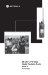
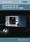
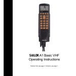
SAILOR A1 VHF-DSC
C4951WP
Operating / Installation Instructions
Distress Call, see page ii. Contents, see page 1.
Introduction
For more than half a century, SAILOR has been synonymous with
state-of-the-art high-quality maritime communications equipment
known for sturdiness, ease of operation and compact design.
SAILOR is a world leader in the technologically advanced field of
maritime communications. A wide range of products from GMDSS
equipment and satellite communications equipment to simple VHF
radios is ensuring the safety at sea and the daily communications
around the world.
The SAILOR A1 Basic and A1 DSC are part of the SAILOR System
4000. This is a full range of maritime communications equipment
developed to increase safety and ease communications for all kinds
of vessels: leisure boats, fishing vessels, cargo ships, and cruise
liners.
The C4951WP control unit for SAILOR A1 VHF is designed for
cockpit installation. The C4591WP has been developed to meet the
harsh environment at sea and is waterproof according to IP67.
As our central concern is fast and professional service, we have
introduced the SAILOR Certified Service Centre (CSC) concept.
Thus, we are able to service your SAILOR VHF equipment in the
best way possible in more than 90 countries all over the world.
Abbreviations used in this manual
ADDR
ATIS
BI
CU
DSC
DUP
DW
GMDSS
GPS
LF
MEM
MMSI
MSG
PTT
RX
SQ
STN
TEL
TX
UTC
Address
Automatic Transfer Identification System
Channel mode when sailing on European rivers (see
page 00)
Control Unit
Digital Selective Calling
Duplex
Dual Watch
Global Maritime Distress and Safety System
Global Positioning System
Low Frequency
Memory
Maritime Mobile Service Identification
Message
Push
Receive/r
Squelch
Station
Telephony
Transmit/ter
Coordinated Universal Time
Please note
Any responsibility or liability for loss or damage in connection with
the use of this product and the accompanying documentation is
disclaimed. The information in this manual is furnished for informational use only, is subject to change without notice, may contain
errors or inaccuracies, and represents no commitment whatsoever.
This agreement is governed by the laws of Denmark.
Doc. No.: B4951GB0
ii
Issue: D/0330
QUICK DSC DISTRESS CALL MAYDAY PROCEDURE
(only for emergency use)
1. Press 16 to enter VHF mode on channel 16.
1. If necessary, switch on by pressing the ON
key.
2. Lift handset off its rest.
3. Lift up lid covering the orange DISTRESS
key and press for 5 seconds.
The TX and Alarm indicator lights will flash.
Release after 5 seconds and wait for answer. Unless stopped manually – by pressing the Cancel key or switching the unit off
– the distress call is automatically transmitted every four minutes or so until acknowledgment is received.
4. To view the call, press RX Log followed by
Select
2. Holding handset, press the PTT (Press To
Talk) key and say:
“MAYDAY”
“This is”
- the 9-digit identity and the call sign or
other identification of the ship,
- The ship’s position,
- The nature of distress and assistance
wanted,
- any other information which might facilitate the rescue.
“OVER.” Release the PTT key and listen
for a answer.
Please note that you can only transmit and
be heard when pressing the PTT key and
you can only receive when it is released.
0203
iii
Your handset at a glance
15
16
17
18
19
20
1
2
3
4
5
6
7
8
9
10
11
12
14
1. Display
10. Channel selection key.
2. Indicator lamps. TX (lit when transmitting). 1W (lit when transmitting at 1 watt). US (lit when using American channels – see page
17). Alarm (lit when sending a distress call).
11. Intercom key.
3. Tel/DSC. Toggles between DSC and normal telephone mode.
13. Function key.
4. RX/Log. Launches a menu for accessing information on calls
received.
14. Shift key.
13
12. Quick-select key for channel 16.
15. Microphone.
5. TX Call. Press to setup DSC call.
16. Earpiece.
6. Send Call. Press to transmit.
17. PTT (Press To Talk) key.
7. On/Off. Please also note that the unit should normally be left
switched On. When switched Off, some information – such as
data input on the vessel’s position – is lost.
18. DISTRESS key.
19. Loudspeaker.
8. Volume controls: increases volume, reduces volume. These up
and down arrows are also used to navigate through menu options.
20. Call (lit when DSC call being received).
9. Squelch key. This is used to control the background noise
present on calls.
iv
0203
Contents - Operator
Introduction ................................................................ ii
Abbreviations used in this manual .......................... ii
QUICK DSC DISTRESS CALL .................................. iii
(only for emergency use)
MAYDAY PROCEDURE ............................................. iii
5 Your VHF DSC in detail ......................................... 5
5.1
5.2
5.3
5.4
5.5
5.6
5.7
5.8
Full VHF telephone operation .................................
Memory scan tables ................................................
Selecting a scan table .............................................
Scanning channels .................................................
Dual watch ..............................................................
Locking the keyboard ..............................................
Unlocking the keyboard ..........................................
Intercom ..................................................................
5
5
5
5
6
6
6
6
Your handset at a glance .......................................... iv
6 DSC operation in detail ........................................ 7
1 Telephone display ................................................. 2
2 Main handset function keys ................................. 2
3 Your VHF DSC in brief .......................................... 2
3.1
3.2
3.3
3.4
3.5
3.6
3.7
3.8
3.9
3.10
3.11
Switching ON/OFF ..................................................
Basic telephone operation ......................................
Listening for telephone calls ...................................
Receiving a call on channel 16 ...............................
Making a telephone call ..........................................
Channel selection ...................................................
Squelch control .......................................................
Adjusting the volume ..............................................
Muting the loudspeaker ..........................................
Setting the transmitter power ..................................
Dimming the display ...............................................
2
2
2
2
2
3
3
3
3
3
3
4 Basic DSC operation ............................................ 4
4.1
4.2
4.3
4.4
4.5
Receiving a DSC Call .............................................
Transmitting a DSC call to a ship station ...............
Transmitting a DSC call to a shore station .............
Transmitting a DSC call to a landline via
shore station ...........................................................
Entering your position into the system ...................
4
4
4
6.1
6.2
6.3
6.4
6.5
6.6
6.7
6.8
6.9
6.10
6.11
6.12
6.13
6.14
6.15
6.16
6.17
6.18
Receiving DSC calls ............................................... 7
Differentiating calls by the ringing tone .................. 7
RX Log menu .......................................................... 8
The RX Log menu tree ........................................... 8
TX Call menu ........................................................ 10
Setting up a call using the EXTENDED TX
Call menu .............................................................. 10
TX Call menu tree .................................................. 11
Function menu ...................................................... 12
Description of function menu items ...................... 13
Function menu tree ............................................... 14
Setting up the directory ......................................... 15
Adding an item to the directory ............................. 15
Viewing/deleting a directory entry ........................ 15
Setting up the address book ................................. 15
Description of VHF system ................................... 15
International Channels .......................................... 16
US Channels ......................................................... 17
BI Channels .......................................................... 18
4
4
Contents - Installation
7 Installation – Control Unit .................................. 19
7.1
7.2
7.3
7.4
7.5
Mounting possibilities ............................................
Power supply ........................................................
Control unit connection – Leisure class D VHF ...
Connecting the transceiver / Control Unit ............
Connecting the transceiver / splitter box / indoor
and waterproof Control Unit ..................................
7.6 Control Unit connection –
Commercial class A VHF ......................................
7.7 Loudspeaker connection .......................................
7.8 Connectors ............................................................
7.9 Installing the Control Unit .....................................
7.10 Linking an external speaker ..................................
19
19
19
19
19
19
19
20
21
21
8.3
8.4
8.5
How to check TX transmitter – handset TX AF
circuits and VHF transmitter) ................................ 25
How to check VHF signal reception –
VHF receiver and handset RX AF circuits) ........... 26
How to check the TX/RX DSC mode .................... 26
9 Installation – Transceiver Unit ........................... 27
9.1
9.2
9.3
9.4
9.5
9.6
9.7
Mounting possibilities / Interface connections .......
Power Supply ........................................................
Aerial .....................................................................
Options Connection Box .......................................
Cable length ..........................................................
Electrical connections ...........................................
Compass safety distance ......................................
27
27
27
28
29
29
29
8 System function checks ..................................... 22
8.1
8.2
0238
How to check system priorities – system control
and SPARC-bus data interface circuits ................ 22
How to check intercom – handset TX AF circuits
and handset audio amplifier circuits ..................... 23
10 Technical specification ....................................... 30
11 Drilling plan - Control Unit ................................. 31
1
Operation
1
Telephone display
Normal display
3
Your VHF DSC in brief
3.1
Switching On/Off
Press the key on the keyboard to switch On.
To switch Off, press and hold for 2 seconds.
3.2
Basic telephone operation
Press Tel DSC or 16 to activate the VHF telephone functions.
3.3
Listening for telephone calls
According to international rules, all ships must continuously monitor
channel 16: that includes yours.
1. Select channel 16 by pressing 16:
Scanning display
2. Set the squelch level using the up and down arrows. If noise is
present, press the up arrow until the hiss disappears. If no noise
is present, press down arrow until hiss is heard, followed by one
press of the up arrow.
To listen for calls on other channels, either select the channel
number or use the scanning facility.
3.4
Receiving a call on channel 16
When you hear your call name in the loudspeaker:
1. Lift the handset.
2. Press the PTT key.
3. Repeat the name of the station calling you and say “This is [your
ship’s name].”
2
Main handset function keys
On/Off
4. Suggest a channel other than 16 by saying “Channel [suggested
number]”.
5. Say “Over” and release the PTT key to allow your caller to
accept the suggested new channel.
Switches the handset on or off.
Tel/DSC
Changes operation mode of handset. Toggles between DSC and
TELEPHONE mode.
RX log
6. Switch to the new channel – for example, channel 71 – and
begin your conversation. Only press PTT when you are talking. If
you are on a simplex channel (in other words, a channel that can
carry just one transmission at a time), always say “Over” just
before releasing. With duplex channels, the conversation can be
two-way as with a normal land telephone call.
Launches DSC menu to read DSC messages.
TX Call
Launches DSC menu to set up DSC calls for transmission.
3.5
Send Call
1. If not already in telephone mode, switch to it by pressing
Tel/DSC or 16.
Transmits the waiting DSC call.
Cancel
Cancels any DSC call that has started. Also cancels a DISTRESS or
DISTRESS Repeat call.
16
Selects Telephone mode and switches to channel 16.
Func
Launches the function menu to set up the handset and system. If the
function menu is already active, it switches to VHF telephone mode.
After 5 minutes of inactivity, the handset automatically defaults to
telephone mode.
2
Making a telephone call
2. Select channel 16 (by pressing 16) or other agreed channel.
3. Lift the handset.
4. Press the PTT key and make your call. First, say the name of the
station you are calling three times. Then say “This is [your ship’s
name”], again three times. Finally, say “Over”.
5. Release the PTT key to listen.
6. When answered, agree upon a channel, switch to that channel –
for example, channel 6 – and begin your conversation. Only
press PTT when you are talking. If on a simplex channel (in other
words, a channel that can carry just one transmission at a time),
always say “Over” just before releasing.
0238
Operation
3.6
Channel selection
There are three ways to select a channel. First, by using the numeric
keys. Second, by using the up or down arrows to move to a higher or
lower number. And third (only for channel 16), by pressing 16.
3.6.1
Channel selection by numeric keys
Press the numeric keys in sequence until the desired channel
number is shown on the display:
If available in your VHF system, a private channel can be selected
by pushing the keys Shift and P before the numeric keys. The
display then shows the letter P in front of the channel number.
3.6.2
If the loudspeaker is active, its setting is always shown on the
display. Only when the handset is off its rest and the speaker is not
set to be active is the volume level of the earpiece shown.
When setting any level using the up or down arrows, holding the key
down for more than 1 second will progress automatically until the
limit is reached.
Channel selection by up and down arrows
First, press CH to display the current channel. Then use the up or
down arrow to locate the channel you require. Finally, press CH
again to exit the selection process.
3.9
Muting the loudspeaker
If the loudspeaker is active, pressing PTT automatically mutes it, and
releasing PTT reactivates it.
To mute the loudspeaker without pressing PTT, press Shift and the 8
key (which also carries a speaker symbol). To reactivate the
speaker, press Shift and 8 again. When the loudspeaker is muted,
the display includes the appropriate icon.
3.10 Setting the transmitter power
3.6.3
Channel selection by quick select key 16
Pressing 16 switches to channel 16 at any time.
3.7
Squelch control
The squelch setting is for suppressing background hiss during a call.
Never use a higher squelch setting than is necessary.
3.7.1
Setting the squelch level manually
First, press SQ to display the current squelch setting (below SQ on
the display). Then use the up or down arrow to adjust. Finally,
press SQ again to exit the selection process. If you press the up or
down arrow for more than 4 seconds, the squelch level goes up or
down automatically.
3.7.2
The transmitter power is either 25W (the default) or 1W: there are no
intermediate settings. To change the TX power level, press Shift,
Power: when the power is 1W, the indicator light will register this.
Please note that some channels are programmed to operate only at
low power, i.e. 1W.
3.11 Dimming the display
The handset features a display backlight, a keyboard backlight and
lights for the five indicators (CALL placed on handset, TX, 1W, US or
BI, and ALARM). The brightness of all of these can be adjusted in
four levels from 3 down to 0. The default setting is 3. To reduce the
level, press Shift and then hold down the 7 key (which also says
DIM). The level is indicated in the display and reduces every second.
Subsequently, pressing any key will return the brightness to level 3.
Setting the squelch level automatically
Your VHF DSC can automatically optimise the squelch level. To do
this, press Shift, SQ.
3.8
Adjusting the volume
The volume can be adjusted by pressing the up or down arrow from
00 (muted) to 15 (loudest). Once the unit is switched OFF and back
ON, the volume will revert to the default setting described below.
The Volume has a default setting for both the loadspeaker and the
earpiece which can be independently adjusted from 00 (muted) to 15
(loudest).
To adjust the loudspeaker:
1. Press Shift, Func.
2. Press the up or down arrow twice to display GENERAL.
3. Press right arrow to display ILLUMINE.
4. Press up arrow to display SOUND.
5. Press right arrow to display EARPIECE.
6. Press up arrow to display LOUDSPEAKER.
7. Press right arrow to display NORM.
8. Now use the up or down arrow to increase or reduce the setting.
9. Once you are satisfied you have keyed in the required setting,
press Shift, Func to exit.
0238
3
Operation
4
Basic DSC operation
When switched on, your VHF set automatically monitors channel 70
for incoming DSC calls.
4.4
Transmitting a DSC call to a
landline via shore station
To set up and transmit a public DSC call via a shore station:
1. Press TX Call.
4.1
Receiving a DSC call
When a DSC call is received, the handset will let you know what kind
of DSC call it is. Immediately, the handset will display the message
dSC RECEIVED, the call indicator lamp will flash, and the loudspeaker will announce the call.
1. If the call includes a proposal for switching to a particular VHF
working channel, the unit will toggle between two displays.
2. If you now lift the handset off its rest, a DSC acknowledgment
call is automatically transmitted, accepting the proposal and
switching both the caller and your handset to the working
channel.
3. You can now begin the call in normal telephone mode.
2. Press the up arrow twice to display SHORE STN.
3. Press the right arrow to display STN 00 *.
4. Key in the nine-digit MMSI number of the shore station you wish
to call, using the numeric keys:
5. Once you are satisfied you have keyed in the correct number,
press right arrow again.
6. Press up arrow, followed by right arrow.
7. Now key in the phone number you wish to call, using the numeric
keys:
8. Once you are satisfied you have keyed in the correct number,
press right arrow twice.
4.2 Transmitting a DSC call to a ship
station
To set up and transmit a DSC call and propose a working channel to
a ship station:
9. Now press Send Call to transmit.
10. Once the call has been sent, the display will indicate that it is
waiting for an acknowledgment:
1. Press TX Call.
2. Press right arrow to display STN *.
3. Key in the nine-digit MMSI number of the ship station you wish to
call, using the numeric keys:
4. Once you are satisfied you have keyed in the correct number,
press right arrow again to display SEND CALL.
5. Now press Send Call to transmit.
6. Once the call has been sent, the display will indicate that it is
waiting for an acknowledgment:
4.5
Entering your position into the
system
If your VHF DSC is not connected to an external GPS system –
which continuously updates your position (please refer to the
installation manual)– you may enter the details as follows. Although it
appears a lengthy procedure, it does not take long and well worth
doing at regular intervals so that, in an emergency, your most recent
position will be included in your DISTRESS call.
To input the position of your vessel:
1. Press Shift Func
2. Press up arrow to display DSC
4.3 Transmitting a DSC call to a
shore station
3. Press right arrow twice to display SELF ID
4. Press up arrow to display POSITION
To set up and transmit a DSC call to a shore station:
5. Press right arrow to display POS VIEW
1. Press TX Call.
6. Press down arrow to display POSUPDATE
2. Press the up arrow twice to display SHORE STN.
7. Press right arrow to display POSITION
3. Press the right arrow to display STN 00 *.
4. Key in the nine-digit MMSI number of the shore station you wish
to call, using the numeric keys:
5. Once you are satisfied you have keyed in the correct number,
press right arrow again.
6. Now press Send Call to transmit.
7. Once the call has been sent, the display will indicate that it is
waiting for an acknowledgment:
8. To enter the first part of your position, use the up or down arrow
to select S or N followed by right arrow and then the relevant
numeric keys. When complete, the word SELECT will appear in
the top right of the display.
9. Press right arrow.
10. To enter the second part of your position, use the up or down
arrow to select E or W followed by right arrow and then the
relevant numeric keys. When the position data is complete, the
word SELECT will appear in the top right of the display.
11. Press right arrow four times to store.
12. Check the stored information by pressing Tel/DSC twice. The
display will now toggle the various details stored.
4
0238
Operation
5
YOUR VHF DSC IN DETAIL
5.1
Full VHF telephone operation
5.1.1
Setting channel mode
Some VHF radios offer a choice between two sets of channels,
called ‘channel modes’. If your unit features two modes, you can
either switch between international and US channels or between
international and BI channels. International mode is used when
sailing on any sea in the world, except in US waters. US mode is
used when sailing in US waters. BI mode is used when sailing on the
rivers of Europe.
5.4
Scanning channels
5.4.1
To start scanning
To start scanning, press Shift, Scan. From left to right, the lower part
of the display shows the number of the scan Table, its name (if it has
one), and its priority channel.
If the Table has not been programmed with any channels, the display
will show the message MEM EMPTY:
5.4.2
To stop scanning
There are four ways to stop scanning.
5.1.2
Choosing international or US channel mode
If your handset offers the choice, you can switch between international and US mode by pressing Shift CH:
When US mode is selected, the yellow US indicator lamp is lit.
Otherwise, the radio is in international mode.
0203
5.1.3
Choosing international or BI channel mode
If your handset offers the choice, you can switch between international and BI mode by pressing Shift CH:
When BI mode is selected, the yellow BI indicator lamp is lit.
Otherwise, the radio is in international mode. When BI mode is
selected, ATIS (Automatic Transfer Identification System) is automatically activated.
5.1.4
Transmitting at 25W power
(for US channels 13 and 67 only)
As described on page 3 under ‘Setting the transmitter power’, the
handset can transmit at 1W or at 25W. However, with handsets
programmed with US channels, some of the channels are restricted
to 1W transmission and the TX power level cannot be changed to
25W as described.
1. By pressing Shift and Scan. The system then resumes normal
VHF operation on the channel selected before scanning began.
2. By pressing 16. The system then resumes normal VHF operation
on channel 16.
3. By lifting the handset off its rest. The system then resumes
normal VHF operation on the channel selected before scanning
began.
4. By pressing PTT. If no signal has been detected on any channel,
the system resumes normal VHF operation on the channel
selected before scanning began. If a signal has been detected
on one or more channels, the system resumes normal VHF
operation on the last channel where a signal was detected.
When a signal is detected during scanning, the display changes to
show the channel number and volume. With priority scanning,
channel 16 is scanned once for every channel scanned in the Table.
Channel 16 cannot be deleted or excluded from this process.
5.4.3
Adding a channel to a scan table
To add a channel to a scan Table, first select the Table (see above)
and check the display. Now select the channel – again check in the
display – and press Shift, Store. For example, to add channel 6 to
scan Table 1:
1. Press Shift, Mem, 1 to select Table 1.
5.2
Memory scan tables
Your VHF DSC has eight independent memory Tables – 0 to 7 – for
storing channels for scanning sessions. Each Table may contain any
of the channels available in the system. To help distinguish between
them, you can attach a name up to seven characters long to each
Table number.
To do this, enter the function menu by pressing Shift and Func (see
page 12). The scan Table number is shown in the left corner of the
handset display beneath MEM.
Three of the Tables – 5, 6 and 7 – are pre-programmed and the
contents cannot be altered in any way. In Table 5, the safety and
security channels are 6 and 13, and the priority channel is 16. Table
6 contains the channels for ship-to-ship communication, apart from 6
and 13. And Table 7 contains all the channels available to the system.
5.3
Selecting a scan table
To select a scan Table, press Shift, Mem followed by the number of
the Table. For example, to select Table 0:
2. Now press 6 to select channel 6.
3. Finally, press Shift, Store. The display shows the message
STORES CHANNEL for 2 seconds.
5.4.4
Deleting a channel from a scan table
To delete a channel from a scan Table, first select the Table (see
above) and check the display. Now select the channel – again check
in the display – and press Shift, Delete. For example, to delete
channel 6 from scan Table 1:
1. Press Shift, Mem, 1 to select Table 1.
2. Now press 6 to select channel 6.
3. Finally, press Shift, Delete. The display shows the message
DELETE CHANNEL for 1 second. The display now shows the
next channel in the Table. If there are no more channels in the
Table and deletion is attempted, the display registers MEM
EMPTY.
1. Press Shift followed by MEM.
The handset shows the message SEL for select and the MEM
symbol flashes. At the same time, the lower part of the display gives
the Scan Table number and name (if it has one).
1. Press 0
The display now shows the new Table number, 0.
0203
5
Operation
5.4.5
Viewing contents of a scan table
There are two ways of checking what channels are in a particular
scan Table. While the key is pressed, the display will cycle through
the channels of the chosen scan Table.
1. Press Shift and then hold down Scan. The display will keep
cycling through the channels – one every second – from low to
high and repeating as long as Scan is pressed.
OR
2. Press Shift and then hold down Mem. The display will keep
cycling through the channels – one every second – from low to
high and repeating as long as Mem is pressed.
5.8
Intercom
If your system has more than one control unit, you can use them for
intercom, as follows:
5.8.1
Initiating an intercom call from the handset
to another control unit
To call another control unit:
1. Press Shift and Inter-C. The display shows SELECT NO asking
you to type in the location number to be called.
2. Press a numeric key – for example 2 – to select the location you
are calling.
5.5
Dual watch
To start a dual watch with priority channel 16 and another channel,
press Shift followed by the number of the second channel. For
example, to start a dual watch with channels 16 and 6, press: Shift
followed by 6.
3. If the location is not available, the display registers IC2 NOT
AVAIL and does not dial the number. If it is available, the display
shows IC2 CALLING and a ringing tone can be heard in the
loudspeaker/earpiece. IC2 indicates that location 2 has been
dialled. The lower part of the display now toggles between
CALLING and the name of the unit called. During the next 30
seconds, you may lift the handset and speak into the microphone. The person receiving the call will then hear you via the
loudspeaker without lifting his handset. In this way, the VHF
system can be used as a sort of paging system.
When a dual watch is in progress, the letters DW appear in the top
left of the display and the priority channel is shown in the bottom
right corner.
4. If the handset is lifted within the first 30 seconds, intercom is
established. If no one answers your call, the handset automatically rings off and reverts to normal VHF operation.
5.5.2
5.8.2
With your VHF DSC, you can monitor two channels at the same time
– a priority channel and your selected channel.
5.5.1
Starting a dual watch
Stopping a dual watch
A dual watch can be ended in three ways.
1. By pressing Shift, DW.
2. By pressing PTT. The system then resumes normal VHF
operation on channel 6 and starts transmitting.
3. By pressing 16. The system then resumes normal VHF operation
on channel 16.
5.6
Locking the keyboard
The keyboard can be locked to avoid unintentional channel changes
during a telephone call. When the keyboard is locked, the only
functions that can be controlled are:
1. The volume.
2. The squelch level.
3. Channel selection using CH followed by the up or down arrow.
What you cannot do with the keyboard locked is change channel
using the numeric keypad.
To lock the keyboard, press Shift once and then again, this time
holding down for 1 second. The key symbol appears on the left of the
display to show the keyboard is locked.
Receiving an intercom call from another
control unit
If someone tries to set up an intercom to your handset:
1. The loudspeaker will broadcast a ringing tone and the display will
toggle between CALLING and the name of the caller. The display
will also show the location number of the caller – for example
IC3 for location 3.
2. To answer, simply lift your handset. Connection between the two
control units is now established. To communicate, simply press
PTT and speak into the microphone.
During an intercom call, you can adjust various features from the
handset:
1. Adjust volume.
2. Mute/activate the loudspeaker.
3. Adjust squelch.
4. Adjust backlight level.
5.8.3
Terminating an intercom call
The intercom connection can be ended by either of the control units,
by:
1. Replacing the handset. VHF mode is resumed.
2. Pressing Shift and Inter-C. VHF mode is resumed.
5.7
Unlocking the keyboard
3. Pressing 16. VHF mode is resumed on channel 16.
The keyboard can be unlocked in two ways:
1. By pressing Shift twice.
2. By pressing 16 for 1 second. This unlocks the keyboard and
switches the unit to channel 16.
6
0238
Operation
6
DSC operation in detail
6.1
Receiving DSC calls
When you receive a DSC call, the handset will ring (see next
section). At the same time, the Call indicator lamp will light and, if it
is a DISTRESS call, the Alarm indicator lamp will also light. In
addition, one of the following will apply.
1. If the handset is on its rest in VHF mode
If the handset is in VHF mode, it automatically switches to DSC
mode. The display toggles with the second screen carrying
limited information on the call.
2. If the handset is on its rest in DSC mode
If the handset is in DSC mode or with its Function menu active, it
continues as normal.
3. If the handset is off its rest in VHF mode
If the handset is in VHF mode, it continues in VHF mode. Press
Tel/DSC to see the display carrying limited information on the
call as in 1.
4. If the handset is off its rest in DSC mode
If the handset is in DSC mode or with its Function menu active, it
continues as normal.
In every case, to view the complete DSC message, press RX/Log
and use the right arrow to step through the information.
6.2 Differentiating calls by the ringing tone
Your VHF DSC rings in various ways according to the nature of the
call, as the following diagram shows.
30 sec.
Restarts
after
30 sec.
TONE SIGNAL
DISTRESS
CALL
DISTRESS &
URGENCY
1 sec.
7 sec.
VHF
CONNECT
3 sec.
ALL SHIP
SAFETY CALLS
OTHER
DSC CALLS
35294
The sequence of each of these repeats every 30 seconds or until the
DSC call is read or answered. If the handset is off its rest, it rings
with a short tone every 30 seconds until the call has been read.
0238
7
Operation
6.3
RX Log menu
The RX log menu enables you to read the entire contents of a DSC
call. It can also be used to set up an acknowledgment response
when requested by the incoming DSC call.
To enter the menu, press RX log followed by the up arrow to cycle
through the following three options:
1. LAST CALL
Select LAST CALL (a) when you have received a DSC call and
the handset is toggling call information, (b) to view all calls and/
or (c) to respond.
2. ALARM LOG
Select ALARM LOG (a) to view a DSC DISTRESS call and (b) to
view all DISTRESS or urgent calls.
3. CALL LOG
Select CALL LOG to view DSC calls from the memory buffer of
the VHF DSC modem.
6.4
The RX Log menu tree
The RX LOG MENU is used for reading information on DSC calls
received. In addition, if requested by a DSC caller, an acknowledgment call can be set up.
The main menu entries are as follows:
1. LAST CALL. Enter this item when a DSC call has been received
and the handset toggles information or when you wish to view all
calls and/or answer back.
2. ALARM CALL. Enter this item to view DSC DISTRESS calls and
all other DISTRESS or urgent calls.
3. CALL. Enter this item to view DSC calls from the VHF DSC
safety or routine ordinary calls buffer.
8
0203
Last call
|
|
Alarm log
|
|
|
|
|
Call log
0203
XXXX info>
XXXX info>
tcmd info
Timeinfo
Rx time>
2 TCMD>
Type info
Calltype
EOS>
Date info
EOS info
Call type>
Distr pos
The call is too old if time
elapsed since rx > 5 mins.
W-ch XX>
Rx date>
Distr MMSI MMSI info
FS info
Lat info
Approve
No comply
CAT info
Distr time
No reason
Congestn
Busy
Queueindi
Stnbarred
No opr
Opr unava
Disabled
Bad-vhfch
Bad mode
From>
Utc XX XX
If EOS = ackn bq
If call already replied
Call repl
Call old
At date
If EOS = RQ and call too old
If EOS = RQ
and call QRW too old
Category>
Long info
Date
D
info
MMSI
M
info
Distr
D
nat
At time
6HQGFDOO
View call
1 TCMD>
Nat info
Time info
tcmd info
Distr com
Re-enter RX
Com info
Operation
9
Operation
6.5
TX Call menu
The TX Call menu offers various ways of setting up DSC calls for
transmission. The options range from totally manual setup using the
extended calls entry and setting up each item of information
involved, to almost automatic setup using the menu entries ADDR
BOOK, SHIP STN, and SHORE STN. A DISTRESS call can be set
up using the DISTRESS option in the TX Call menu. Alternatively,
and more simply, pressing the orange DISTRESS key automatically
transmits a DISTRESS call.
To access the menu, first press TX Call. Pressing the up arrow then
cycles through the following options. At each level, use the left and
right arrows to select further options.
SHIP STN
Your input: MMSI number or a station stored in the station register,
change of working channel if desired.
Call setup: Automatic, individual routine including VHF working
channel, requests acknowledgment.
ADDR BOOK
Your input: Name from the address book.
Call setup: Automatic, depending on: Ship station: Shore station:
Shore station including telephone number:
SHORE STN
Your input: MMSI number or pre-stored station from the station
register, optional telephony number.
8. Press right arrow followed by up or down arrows to select
SAFETY. (The other options here are ROUTINE, URGENCY and
DISTRESS.)
9. Press right arrow to display 1 TELECMD.
10. Press right arrow and then use up or down arrows to select
SIMPLEX. (The other options here are NO-INFO and NO
COMPLY.)
11. Press right arrow to display ADD W-CH (add VHF working
channel).
12. Press right arrow and then enter the number of the working
channel for example “16”.
13. Press right arrow to display CALL ANSW.
14. Press right arrow followed by up or down arrows to select
REQ ANSW. (The other option here is NO ANSWER.)
15. Press right arrow to display SEND CALL.
16. Finally, to transmit the call, press Send Call.
Once the call has been transmitted, the handset waits for an
acknowledgment that the call has been received.
Please note that it is not always possible to backtrack if an incorrect
choice is made in the menu selection. If this happens, cancel the
procedure – for example by pressing 16 – and re-enter your
selections.
Call setup: Automatic, depending on: Telephone number included:
No telephone number included:
EXTENDED
Your input: All information in call.
Call setup: As specified by user.
DISTRESS
Your input: Nature of DISTRESS, position and time. If connected to
GPS, time and position are automatically inserted.
Call setup: A standard DISTRESS call.
ALL SHIP
Your input: Change of working channel if desired.
Call setup: Automatic. All ships, safety, including VHF working
channel.
6.6
Setting up a call using the
EXTENDED TX Call menu
The following example goes through the various stages of setting up
a DSC call in the EXTENDED TX Call menu.
1. Press TX Call.
2. Press the up arrow three times to display EXTENDED.
3. Press right arrow to display CALL TYPE.
4. Press right arrow followed by up or down arrows to select
INDV-STN. (The other option here is an ALL-STN call.)
5. Press right arrow to display MMSI.
6. Key in the nine-digit MMSI number of the ship or shore station
you wish to call, using the numeric keys. When all nine digits
have been entered, the word SELECT will appear at the top right
of the display.
7. Press right arrow to display CATEGORY.
10
0238
Operation
6.7
Ship stn
|
|
Addr book
|
|
Shore stn
|
|
Extended
|
|
|
|
|
|
|
|
|
|
Distress
|
|
|
|
|
|
|
|
|
|
|
|
All ship
0238
TX Call menu tree
Stn XXX
6HQGFDOO
View call
name XXX 6HQGFDOO
View call
Stn XXX
No Phone
Add Phone No XXX
Call type Indv-stn
|
|
|
|
All-stn
6HQGFDOO
View call
MMSI XXXCategory Routine
Safety
Urgency
Distress
Category Safety
Urgency
Distress
1 Telecmd Simplex
Add W-ch VHFCH XX
No-info
No W-ch
No comply
1 Telecmd Simplex
No-info
If NO valid GPS input
Nature of Fire
Key pos> Known
Lat edit
Long edit
Flooding
Unknown
Collision
Grounding
If valid GPS input
Listing
Sinking
Adrift
Undesignd
Abandship
Piracy
Manoverb
Add W-ch VHFCH XX
No W-ch
6HQGFDOO
View call
Key time
6HQGFDOO
View call
Time edit
Call answ Req answ 6HQGFDOO
No answer View call
W-ch XX 6HQGFDOO
View call
11
Operation
6.8
Function menu
The function menu enables you to set up and check the various
functions of the handset. It also offers facilities to view and change
the functions of the VHF transceiver and of the DSC modem.
6.8.1
To enter the function menu
To set up or view items in the function menu, press Shift, Func. The
display will read TELEPHONY.
6.8.2
To move around the function menu
1. Use the up and down arrows to locate the function – DSC,
GENERAL or SERVICE.
2. Press the right arrow to select the function.
3. Press and hold the left arrow for 1 second to go back to function
selection.
6.8.3
To edit items in the function menu
1. Use the up and down arrows (a) to toggle between Y (yes) and
N (no) and (b) to change single numeric values up or down until
the limit is reached.
2. Use the right arrow (a) to select an item and move to the next
and (b) to move a step to the right in an item with more than one
input.
3. Use the left arrow (a) to delete the character to the left of the
cursor and (b) by holding for 1 second to go back to function
selection.
4. Use the alphanumeric keys to enter data at the cursor position.
6.8.4
To exit the function menu
If you have changed any setting while in the function menu, you
must turn the handset off and then on again for the changes to take
effect. You can exit in one of the following ways:
1. By pressing 16 to activate channel 16 in VHF mode.
2. By pressing Shift, Func to activate VHF mode on the last
channel you used.
3. By pressing Tel DSC to activate VHF mode on the last channel
you used.
4. By pressing RX Log to enter the DSC RX log menu.
Example
To activate a keyboard beep every time a key is pressed:
1. Enter the function menu by pressing Shift, Func. The display
will read TELEPHONY.
2. Press the up or down arrow twice to display GENERAL.
3. Press the right arrow to display ILLUMIN.
4. Use the up or down arrow to locate SOUND.
5. Press the right arrow to display EARPIECE.
6. Press the up or down arrow twice to display KEYBOARD.
7. Press the right arrow to display KB.BLEEP N
8. Now use the up or down arrow to toggle the final Y (Yes) or N
(No) to select.
9. Finally, press the right arrow to re-enter the function menu. To
activate the new setting, turn the handset off and then back on
again.
12
0203
Operation
6.9
Description of function menu items
Path:
Data:
DSC\SETTINGS\ACKNOWLDG\AUTOACK
Description:
‘Y’ enables automatic acknowledgment of
"Y"/"N" incoming DSC calls
GENERAL\ILLUMIN\INDICATOR\LEVL_0-3
0-3
GENERAL\ILLUMIN\DISPLAY\DB_L_0-3
0-9
GENERAL\ILLUMIN\DIMMER\D_LEVL
0-3
GENERAL\ILLUMIN\DIMMER\D_LEVL\DIMDIR
0-2
GENERAL\ILLUMIN\KEYB0ARD\SECS
0-20
GENERAL\ILLUMIN\KEYB0ARD\SECS\D_LEVL 0-3
GENERAL\SOUND\EARPIECE\NORM
0-15
GENERAL\SOUND\EARPIECE\NORM\ALARM
0-15
GENERAL\SOUND\LOUDSPEAK\NORM
0-15
GENERAL\SOUND\LOUDSPEAK\NORM\ALARM 0-15
GENERAL\SOUND\LOUDSPEAK\NORM\ALARM
\EXT_SPK
0-3
GENERAL\SOUND\LOUDSPEAK\NORM\ALARM
\EXT_SPK\HO_SPK
0-1
GENERAL\SOUND\KEYB0ARD\KBBEEP
GENERAL\SOUND\SIDETONE\ST ATT
SERVICE\DSC\SELF-ID\GRPEDIT
SERVICE\TELEPHONY\CH+MODE\INPUTS
0203
Brightness levels of each indicator lamp
Brightness levels of each backlight display
lamp
Brightness level when handset switched on
Start direction of brightness level (see
diagram on next page)
Number of seconds light is on after a key
has been pressed
Brightness level when any key has been
pressed, as long as above setting is at least
1 second
Volume level in earpiece when handset is
switched on
Volume level in earpiece when DSC call or
intercom received
Volume of speaker when handset is switched
on
Volume of speaker when DSC call or
intercom received
Handset control of external speaker
Speaker state when handset is off its rest.
Default on = 1 or off = 0
"Y"/"N" Beep from keys when pressed
Feedback level of microphone to earpiece.
0-3
Recommended setting = 1
0-9
Set up or change Group MMSI number
Set up number of digits to be input when
changing VHF channel. Y = 3 digits, N = 2
"Y"/"N" digits
13
Operation
6.10 Function menu tree
Telephony
|
|
|
|
Dsc
|
|
|
|
|
|
|
|
|
|
|
|
|
|
|
|
|
|
|
|
|
|
|
General
|
|
|
|
|
|
|
|
|
|
|
|
|
Service
14
Scanner
Squelch
Atis no
Mem_no X Name XXX
Mode X
XXXXXXXXX
Settings
|
|
|
|
|
|
|
|
|
|
|
|
|
Addr book
|
|
Directory
|
|
Testcalls
Self-id
|
Position
|
|
|
|
Acknowldg
|
Time date
Pr-ch XX
Pr_sc X
MMSI-NU> XXXXXXXXX GrpMMSI
XXXXXXXXX
Posview
X:XX’XX
Pos auto
X:XX’XX
Pos mode Show X
Posupdate X:XX’XX
X:XXX’XX
X:XXX’XX
Utc time
Utc XX:XX
X:XXX’XX
AT Utc
HXX MXX
XX XX XX
Hour XX
Date
Mins XX
Autoack X
View
Set
Tzone XX
Tzone XX
Add name
View del
Name XXXX Mmsi XXX
Name XXXX Mmsi XXX
Add stn
View del
Name XXXX Mmsi XXX
Name XXXX Mmsi XXX
Localtime
Utctime
XX XX XX
Secs XX
Date
Year XX
Month XX
Day XX
Phone XXX
Press sto
Phone XXX
If coast stn, phone number can be added for public call
Press sto
Int path
Ext path
Illumin
|
|
|
|
Sound
|
|
|
|
|
Version
Indicator
Display
Dimmer
Keyboard
Levl_0 X
Levl_0 X
D_levl X
Secs XX
Levl_1 X
Levl_1 X
D_dir X
D_levl X
Levl_2 X
Levl_2 X
Levl_3 X
Levl_3 X
Earpiece
Loudspeak
Keyboard
Sidetone
Norm XX
Norm XX
Beep X
St att X
Alarm XX
Alarm XX
Extspk X
Ho spk X
Handset
Transceiv
Software
Software
XXXXXX
XXXXXX
Serial no
Serial no
XXXXXXXX
XXXXXXXX
Code
Bus setup
DSC
Telephony
Handset
Self-id
CH_mode
Loc no X
GRP edit
Input 3 x
Name XXXX
XXXXXXXXX
0203
Operation
6.11 Setting up the directory
6.14 Setting up the address book
The directory, which is a subset of the DSC items in the function
menu, can be programmed with the most frequently used stations.
Both the number and name can be stored, if required. These can
then later be retrieved for use in the TX Call menu. Entries can also
be deleted if seldom used.
The directory makes it easier and quicker to set up DSC calls using
the SHIP or SHORE items in the DSC TX Call menu, the MMSI
number being selected via identification name.
The ADDR BOOK is a subset of the DSC items in the function menu
and is very similar to the directory. However, with a coastal station
entry, it does offer the extra facility of adding a public telephone
number to the name and MMSI number.
The directory makes it easier and quicker to set up DSC calls using
the ADDR BOOK item in the DSC TX Call menu.
To use the address book, follow the same procedure as for the
directory but adding a public telephone number to the name.
6.12 Adding an item to the directory
To add an entry to directory:
6.15 Description of VHF system
1. First enter the function menu by pressing Shift, Func. The
display will read TELEPHONY.
Up to seven control units may be connected to the VHF system,
each with a unique location (1–7). However, only one of these – the
master control unit – may control the transceiver. The various
displays for different system priorities of the control units are
described below.
2. Use the up or down arrow to locate DSC.
3. Press the right arrow to display DIRECTORY.
4. Press the right arrow followed by up or down arrows to locate
ADD STN.
The control unit designated location 1 has the highest priority in the
VHF system and is able to become master of the system whenever
required. When several control units are connected to the system,
the main control unit has to be assigned location 1.
5. Press the right arrow and to display NAME
6. Now enter the name of the new item. This must be nine characters long, including spaces. If the name is shorter than this, add
spaces (using the 0 key) until the total is nine. Use the alphanumeric keys to enter the name, cycling through the selection. For
example, to type the O of POSEIDON, press the MNO key three
times. Then move to the next character by pressing the right
arrow. When all nine characters or spaces have been typed, the
display will show SELECT in the top right.
7. Press the right arrow to select MMSI.
8. Now enter the nine-digit number of the item.
9. Press the right arrow to display PRESS STO.
10. Finally, store the name and number by pressing Shift, Store.
6.13
Viewing/deleting a directory entry
To view/delete a directory entry:
1. First enter the function menu by pressing Shift, Func. The
display will read TELEPHONY.
6.15.1
When the system is free
If the handset is in VHF mode, the display will show: the selected
channel
If the handset is in DSC mode or the function menu is active, the
display will show: dSC and SHIP STN.
6.15.2
When a control unit is master of the system
When a control unit is master of the system, any other control units
in VHF mode will show the following display to indicate that the
transceiver is in use by another control unit: oCC and name and
number of control unit in use.
Any control units in DSC mode or with their the function menu active
will display the normal menu screen.
6.15.3
How master priority is obtained
Before a handset can operate the transceiver, it has to have priority
in the system. This is achieved by simply lifting the handset off its
rest. If the system is clear for the handset to transmit, the display
does not change.
2. Use the up or down arrow to locate DSC.
If another handset is already in use, the display will read: oCC and
name and number of control unit in use.
3. Press the right arrow to display DIRECTORY.
In that case, hang up and wait for the system to become free.
4. Press the right arrow followed by up or down arrows to locate
VIEW DEL.
5. Pressing the right arrow will now display the name of the last
station used.
6. Now either
a) use the up and down arrows to cycle through the stored names
or
b) press the right arrow to view the MMSI number
or
c) press Shift, Del to delete the entry when the name is displayed.
When an entry is deleted, the next one in the memory is
displayed. If the directory is empty, the display reads MEM
EMPTY.
0238
15
Operation
6.16 International Channels
&KDQQHOV
1
2
3
4
5
6
7
8
9
10
11
12
13
14
15
16
17
18
19
20
21
22
23
24
25
26
27
28
7;
0+]
156,050
156,100
156,150
156,200
156,250
156,300
156,350
156,400
156,450
156,500
156,550
156,600
156,650
156,700
156,750
156,800
156,850
156,900
156,950
157,000
157,050
157,100
157,150
157,200
157,250
157,300
157,350
157,400
5;
6,03/(;
'83/(;
0+] ,QWHUVKLS
3RUW
3RUW
3XEOLF
160,650
160,700
160,750
160,800
160,850
156,300
160,950
156,400
156,450
156,500
156,550
156,600
156,650
156,700
156,750
156,800 'LVWUHVVDQGFDOOLQJ
156,850
161,500
161,550
161,600
161,650
161,700
161,750
161,800
161,850
161,900
161,950
162,000
&KDQQHOV
60
61
62
63
64
65
66
67
68
69
70
71
72
73
74
75
76
77
78
79
80
81
82
83
84
85
86
87
88
7;
0+]
156,025
156,075
156,125
156,175
156,225
156,275
156,325
156,375
156,425
156,475
156,525
156,575
156,625
156,675
156,725
156,775
156,825
156,875
156,925
156,975
157,025
157,075
157,125
157,175
157,225
157,275
157,325
157,375
157,425
5;
6,03/(;
'83/(;
0+] ,QWHUVKLS
3RUW
3RUW
3XEOLF
160,625
160,675
160,725
160,775
160,825
160,875
160,925
156,375
156,425
156,475
156,525
'6&
'6&
156,575
156,625
156,675
156,725
156,775
/
156,825
/
156,875
161,525
161,575
161,625
161,675
161,725
161,775
161,825
161,875
161,925
157,375
157,425
Notes
L) 1W TX power
*)
Channels 87 and 88 became simplex channels following the
introduction of Automatic Identification channels AIS1 at
161.975MHz and AIS2 on 162.025MHz.
NB The RX and TX frequencies can be read from the handset
display by pressing and holding the CH key for more than 1
second. With a front-operated VHF radio, the frequencies can be
displayed on a menu.
16
0203
Operation
6.17 US Channels
&KDQQHOV
1
2
3
4
5
6
7
8
9
10
11
12
13
14
15
16
17
18
19
20
21
22
23
24
25
26
27
28
7;
5;
6,03/(;
0+]
0+]
156,050 156,050
'83/(;
%
156,150 156,150
%
156,250
156,300
156,350
156,400
156,450
156,500
156,550
156,600
156,650
156,700
156,800
156,850
156,900
156,950
157,000
157,050
157,100
157,150
157,200
157,250
157,300
157,350
157,400
156,250
156,300
156,350
156,400
156,450
156,500
156,550
156,600
156,650
/
156,700
156,750
5;
156,800 'LVWUHVVDQGFDOOLQJ
156,850
156,900
156,950
157,000
157,050
157,100
157,150
161,800
161,850
161,900
161,950
162,000
&KDQQHOV
60
61
62
63
64
65
66
67
68
69
70
71
72
73
74
75
76
77
78
79
80
81
82
83
84
85
86
87
88
7;
0+]
5;
0+]
6,03/(;
'83/(;
&KDQQHOV
%
P1
P2
P3
P4
P5
P6
P7
P8
P9
P10
156,075 156,075
%
156,175
156,225
156,275
156,325
156,375
156,425
156,475
156,525
156,575
156,625
156,675
156,725
156,175
156,225
156,275
156,325
156,375
156,425
156,475
156,525
156,575
156,625
156,675
156,725
/
:;
WX1
WX2
WX3
WX4
WX5
WX6
WX7
WX8
WX9
WX10
5;
0+]
162,550
162,400
162,475
162,425
162,450
162,500
162,525
161,650
161,775
163,275
'6&
%
%
156,875
156,925
156,975
157,025
157,075
157,125
157,175
157,225
157,275
157,325
157,375
157,425
156,875
156,925
156,975
157,025
157,075
157,125
157,175
161,825
161,875
161,925
161,975
157,425
/
Notes:
L)
B)
!)
RX)
NB!
0203
1 W TX power. Pressing the 25W button in the US rest will
make the unit transmit at 25W on channel 13 and 67,
normally limited to 1W.
Channels 2, 4, 60, 62, 75 and 76 cannot be selected in US
mode.
Channels 3, 21, 23, 61, 64, 81, 82 and 83 may be legally
used in some circumstances but not by the general public in
US waters.
Only RX: transmissions are blocked.
The RX and TX frequencies can be read from the handset
display by pressing and holding the CH key for more than 1
second. With a front-operated VHF radio, the frequencies
can be displayed on a menu.
17
Operation
6.18 BI Channels
&KDQQHOV
1
2
3
4
5
6
7
8
9
10
11
12
13
14
15
16
17
18
19
20
21
22
23
24
25
26
27
28
7;
0+]
156,050
156,100
156,150
156,200
156,250
156,300
156,350
156,400
156,450
156,500
156,550
156,600
156,650
156,700
156,750
156,800
156,850
156,900
156,950
157,000
157,050
157,100
157,150
157,200
157,250
157,300
157,350
157,400
5;
6,03/(;
'83/(;
0+] ,QWHUVKLS
3RUW
3RUW
3XEOLF
160,650
160,700
160,750
160,800
160,850
156,300
/
160,950
156,400
/
156,450
156,500
/
/
156,550
/
156,600
/
156,650
/
/
156,700
/
156,750
/
/
156,800 'LVWUHVVDQGFDOOLQJ
156,850
/
/
161,500
161,550
161,600
161,650
161,700
161,750
161,800
161,850
161,900
161,950
162,000
&KDQQHOV
60
61
62
63
64
65
66
67
68
69
70
71
72
73
74
75
76
77
78
79
80
81
82
83
84
85
86
87
88
7;
0+]
156,025
156,075
156,125
156,175
156,225
156,275
156,325
156,375
156,425
156,475
156,525
156,575
156,625
156,675
156,725
156,775
156,825
156,875
156,925
156,975
157,025
157,075
157,125
157,175
157,225
157,275
157,325
157,375
157,425
5;
6,03/(;
'83/(;
0+] ,QWHUVKLS
3RUW
3RUW
3XEOLF
160,625
160,675
160,725
160,775
160,825
160,875
160,925
156,375
156,425
156,475
156,525
'6&
'6&
156,575
/
156,625
/
156,675
156,725
/
156,775
%
156,825
%
156,875
/
161,525
161,575
161,625
161,675
161,725
161,775
161,825
161,875
161,925
157,375
157,425
Notes:
B) Channels 75 and 76 cannot be selected in BI mode.
L) 1W TX power on channels 6, 8, 10, 11, 12, 13, 14, 15, 17, 71,
72, 74 and 77.
*)
Channels 87 and 88 became simplex channels following the
introduction of Automatic Identification channels AIS1 at
161.975MHz and AIS2 on 162.025MHz.
NB The ATIS function is enabled on all channels. RX and TX
frequencies can be read from the handset display by pressing
and holding the CH key for more than 1 second. With a frontoperated VHF radio, the frequencies can be displayed on a
menu.
18
0203
Installation - Control Unit
7
Installation – Control Unit
7.1
Mounting possibilities
Mounting is carried out by first fixing the backplate, after which the
Control Unit can simply be slid over and clicked into place. There is
a template on page 31 to help you mount the unit.
To avoid theft, the control unit can be removed when leaving the boat
or during the off-season simply by pressing the spring and lifting it
off the backplate
7.2
Control Unit connection –
Commercial class A VHF
Remote control units can be connected in two ways:
1. Directly between the transceiver and the control unit .
2. Via a SPARC-bus splitter box or WP SPARC-bus connection box.
Both control units with or without DSC can be connected.
Remote speakers may be connected to remote Control Units, to a
splitter box , or via a WP SPARC-bus connection box.
Power supply
The Control Unit is supplied with +12V DC from the SPARC-bus
interface.
If there is a short circuit or fire, it is important that your VHF remain
operational. We therefore recommend that the power cable be
connected directly to the ship’s battery.
7.3
7.6
Not more than seven handsets can be simultaneously connected to
the transceiver with DSC. Always connect the local Control unit to
the transceiver. The DSC class of intelligent Control Unit is ‘D’ even
if the radio is Class A.
Indoor
Control unit connection –
Leisure class D VHF
Outdoor
TX 1W US
Remote control units can be connected in two ways
CALL
ALARM
Transceiver
12V DC
Rx
/
Tx
1. Directly between the transceiver and the control unit .
SPARC-BUS
OPTION
HANDSET
PRINTER
2. Via a SPARC-bus splitter box or WP SPARC-bus connection
box (optional, not included).
Both control units with or without DSC can be connected.
Remote speakers may be connected to remote Control Units via a
splitter box , or a WP SPARC-bus connection box.
Not more than four Control Units can be simultaneously connected
to a transceiver without DSC and not more than seven with DSC.
7.4
Connecting the transceiver /
Control Unit
56.114
Factory delivered
38051A
7.7
Loudspeaker connection
When one or more control units are connected to the VHF system,
two of them can be set up to use the transceiver’s two loudspeaker
outputs to drive external speakers.
To link a loudspeaker to a control unit:
Indoor
1. Lift the handset.
2. Press Shift, Func to display TELEPHONY.
Transceiver
X1
3. Press down arrow twice to display GENERAL.
4. Press right arrow once to display ILLUMIN.
5. Press down arrow twice to display SOUND.
38050
6. Press right arrow once to display EARPIECE.
7. Press up arrow once to display LOUDSPEAK.
7.5
Connecting the transceiver /
splitter box / indoor and
waterproof Control Unit
Indoor
Outdoor
TX 1W US
CALL
9. Use up and down arrows to set external speaker to 1 or 2, as
required.
10. Press right arrow to complete selection. If you make a mistake
at any step, simply press 16 to return to the beginning. It is not
possible to step backwards through the menu sequence.
ALARM
Transceiver
X1
WP SPARC-Bus connection
(Optional)
56.114
8. Press right arrow three times to display EXTSPK.
Loudspeaker signals are available in the SPARC-bus cabling, and a
loudspeaker can be connected to the system rest, in the SPARC-bus
splitter box, or in the WP SPARC-bus connection box. Connect the
loudspeaker cables to SPARC-bus signals (LS_1+ and LS1_!) or
(LS_2+ and LS_2!) depending on which speaker selection is made
by the control unit(s).
Factory delivered
38052A
0310
19
Installation - Control Unit
7.8
Connectors
SPARC-bus splitter box
WP SPARC-bus connection box
SPARC-
3
4
AF+
4
5
AF-
5
6
-BAT
6
7
+12VDC
7
-BAT
8
2
SPARC+
3
1
2
1
SUPPLY
_ON
+12VDC
SPARC+
SPARC-
RX_AF+
9
RX_AF-
9
10
+12VDC
10
X2
AF+
8
X3
X1
SUPPLY_ON
AF-
RX_AF+
RX_AF+12VDC
11
11
LS_1+
LS_1+
12
13
-BAT
LS_2+
13
LS_1-BAT
14
14
12
LS_1-
LS_2+
15
15
LS_2-
LS_2-
Shield
NC
37394
35349A
SPARC-bus cable
For systems with a supply voltage of +12V, the table below gives the maximum length of the SPARC-bus cable for the supply to a single
control unit furthest away from the transceiver. The cable length depends on the number of supply wires and the wire thickness. For a +24V
supply the maximum cable lengths listed may be doubled.
1XPEHU
6\VWHP
VXSSO\
+12 Volt
+12 Volt
+12 Volt
+12 Volt
56.114
1XPEHURI
ZLUHVLQFDEOH
2x8
2x8
2x8
2x8
)URP
7R
Transceiver
Transceiver
Transceiver
Transceiver
CU
CU
CU
CU
:LUH
PP
0.25
0.50
0.75
0.14
1XPEHURIZLUHV 1XPEHURIZLUHV 0D[
%$7729'&
9'&
OHQJWK
2
2
30 metres
2
2
60 metres
2
2
100 metres
3
2
5 metres
The SPARC-bus cable length is limited by the output power delivered to an external speaker connected to the LS2 terminals. The speaker
output power depends on cable length and cable thickness as in the table below
:LUH>PP@
0.14
0.25
0.25
0.50
0.50
0.75
0.75
/HQJWK>P@
5
10
20
20
40
30
60
0D[3RZHU>:@
3.4
3.2
2.0
3.2
2.0
3.2
2.0
56.114
35356
SPARC-bus/Option cable 5 metres 56.114
3LQQR
pin 1
pin 2
pin 3
pin 4
pin 5
pin 6
pin 7
pin 8
pin 9
pin 10
pin 11
pin 12
pin 13
pin 14
pin 15
Shield
20
1DPH
SUPPLY_ON
SPARC+
SPARCAF+
AF-BAT_0VDC
+12VDC
RX_AF+
RX_AF+12VDC
LS_1+
LS_1-BAT_0VDC
LS_2+
LS_2-
&RORXU
7ZLVWHGSDLU
Red/White
7
Yellow
1
Yellow/White
1
Blue/White
2
Blue
2
Red and Orange
7/8
Orange/White
8
Green/White
3
Green
3
Black/White
6
Brown
4
Brown/White
4
Black
6
Purple
5
Purple/White
5
Shield
SPARC-bus connections
7UDQVFHLYHU
XQLW
;
pin 1
pin 2
pin 3
pin 4
pin 5
pin 6
pin 7
pin 8
pin 9
pin 10
pin 11
pin 12
pin 13
pin 14
pin 15
1DPH
7ZLVWHG +DQGVHW
SDLU
+22.
;;
SUPPLY_ON
1
SPARC+
1
2
SPARC1
3
AF+
2
4
AF2
5
-BAT_0VDC
6
+12VDC
7
RX_AF+
3
8
RX_AF3
9
+12VDC
10
LS_1+
4
11
LS_14
12
-BAT_0VDC
13
LS_2+
5
14
LS_25
15
63$5&EXV
FRQQHFWLRQER[
;;;
1
2
3
4
5
6
7
8
9
10
11
12
13
14
15
0330
Installation - Control Unit
7.9
Installing the Control Unit
1. With the VHF system turned off, connect the control unit- to the
system as described above.
2. Switch the VHF system on by pressing the ON/OFF button
3. The next step is to set up the control unit SPARC-bus location
number and SPARC-bus handset name by the following steps.
4. Press Shift, Func to display TELEPHONY.
5. Press down arrow to display SERVICE.
6. Press right arrow. An asterisk will flash.
7. Key in your access code 9876 using the alphanumeric keys. To
enter the first digit, press the appropriate key rapidly four times
to display the digit. Then pause for two seconds until the asterisk
moves to the right. Now enter the second digit by pressing four
times in quick succession. Continue until all four digits have
been entered. If you make a mistake, use the left arrow to move
backwards and cancel.
8. Press right arrow three times, to display BUS SETUP, HANDSET
and LOC NO in turn.
9. Use up or down arrow to change SPARC-bus location number.
10. Press right arrow.
11. Use the Func and Power keys to enter or change the name of
the handset.
12. Press right arrow to move one character to the right or select
the name already entered.
13. To finish setup, press Shift and Func. Alternatively, just press 16.
7.10 Linking an external speaker
If an external speaker is to be linked to the handset, proceed as
follows.
1. Lift the handset.
2. Press Shift, Func to display TELEPHONY.
3. Press down arrow twice to display GENERAL.
4. Press right arrow once to display ILLUMIN.
5. Press down arrow twice to display SOUND.
6. Press right arrow once to display EARPIECE.
7. Press up arrow once to display LOUDSPEAK.
8. Press right arrow three times to display EXTSPK.
9. Use up and down arrows to display 0 for no external speaker
selected, 1 for external speaker 1, 2 for external speaker 2, or 3
for both external speakers.
10. Press right arrow to complete selection. If you make a mistake
at any step, simply press 16 to return to the beginning. It is not
possible to step backwards through the menu sequence.
ATTENTION: When more control units are connected to the VHF
system, they all have to be assigned different location numbers for
the system to function correctly. The control unit at a ship’s central
control should be assigned location number 1. Under the VHF
system, the control unit with location number 1 has the highest
priority in the system and so is able to control the system at any
time.
0238
21
Installation - Control Unit
8
System function checks
After a handset has been connected to the VHF system, go through the following test procedures to ensure the system is working properly. If
the tests are successful, the VHF system is functioning correctly.
Purpose:
To test correct assembly of the system, ensuring SPARC-bus command communication between all system units – including
system control priorities for the control units – and to check the telephony TX LF and RX LF routing.
Test setup:
Switch all control units on, with all handsets on their rests and each showing VHF display.
8.1
How to check system priorities –
system control and SPARC-bus data interface circuits
If only one control unit is connected, lift the handset and change the channel or push PTT once to ensure the handset is able to control the
system. If more control units are connected, do the following:
Test setup
Result expected
1a
Handset loc_1: VHF display.
Handset (loc_1):
Hook off.
16
MEM
VOL
SQ
0 08 01
Other control units: oCC display.
oCC
1 “NAME”
1b
Other control units in
Hook off.
Handset loc_1: VHF display.
16
MEM
VOL
SQ
0 08 01
Other control units: oCC display.
oCC
1 “NAME”
2
All control units:
Hook on.
All control units: VHF display (system idle).
16
MEM
VOL
SQ
0 08 01
3a
Handset (loc_2):
Hook off.
Handset loc_2: VHF display.
16
MEM
VOL
SQ
0 08 01
Other control units: oCC display.
oCC
2 “NAME”
3b
Handset (loc_1):
Hook off.
Handset loc_1 or loc_2: VHF display.
16
MEM
VOL
SQ
0 08 01
Other control units: oCC display.
oCC
1 “NAME”
22
0203
Installation - Control Unit
3c
Handset (loc_1):
Hook on.
Handset loc_2: VHF display.
16
MEM
VOL
SQ
0 08 01
Other control units: OCC display.
oCC
2 “NAME”
3d
Handset (loc_3):
Hook off.
Handset loc_2: VHF display.
16
MEM
VOL
SQ
0 08 01
Other control units: OCC display.
oCC
2 “NAME”
3e
Handset (loc_3):
Hook on.
Handset loc_2: VHF display.
16
MEM
VOL
SQ
0 08 01
Other control units: OCC display.
oCC
2 “NAME”
3f
Handset (loc_2):
Hook on.
All on hook.
All control units: VHF display (system idle).
16
MEM
VOL
SQ
0 08 01
If the various control units do not behave as described, some of them may have been assigned the same location number. If so, check the
location number setup in each unit.
8.2
How to check intercom –
handset TX AF circuits and handset audio amplifier circuits
If only one control unit is connected, ignore this test. If other control units are connected, proceed as follows.
Test setup
Result expected
1
Handset (loc_1): Inter-C dial display
and dialling tone in the handset.
Handset (loc_1):
IC2
CALLING
Handset (loc_2): Inter-C dial display
and dialling tone in the handset.
IC1
CALLING
Other control units: VHF display.
2
Handset (loc_1):
16
Handset (loc_1): Inter-C dial display
MEM
VOL
SQ
0 08 01
0238
23
Installation - Control Unit
Hook off.
and dialling tone in the handset.
Handset (loc_2): Inter-C dial display
and dialling tone in the handset.
Other control units: VHF display.
IC2
CALLING
IC1
CALLING
16
MEM
VOL
SQ
0 08 01
3
Handset (loc_1):
Press PTT and talk.
Handset (loc_1): Inter-C dial display
and dialling tone in the handset.
IC2
CALLING
Handset (loc_2): Voice output in speaker
and dialling tone in the handset.
IC1
CALLING
Other control units: VHF display.
16
MEM
VOL
SQ
0 08 01
4
Handset (loc_2):
Hook off.
Handset (loc_1): Inter-C display.
IC2
“NAME 2”
Handset (loc_1): Inter-C display.
Intercom in progress, talk both ways.
Voice in both handset
earpieces/speakers.
IC1
“NAME 1”
16
Other control units: VHF display.
MEM
VOL
SQ
0 08 01
5
Handset (loc_1):
Hook on.
Handset (loc_2): VHF display.
16
MEM
VOL
SQ
0 08 01
Other control units: oCC display.
oCC
2 “NAME”
24
0238
Installation - Control Unit
6
Handset (loc_2):
Hook on (all on hook)
All control units: VHF display (sys idle).
16
MEM
VOL
SQ
0 08 01
8.3
How to check TX transmitter –
handset TX AF circuits and VHF transmitter
For this test, transmitter power level must be 25W (that is, the 1W indicator lamp will not be lit). If the VHF transmitter fails, the 1W indicator
lamp will go on when the PTT button is pressed and/or the display will show the error message ANTN FAIL. In this event, check that the aerial
and aerial cable are connected correctly.
Test setup
Result expected
1
Handset (loc_1): VHF display.
Handset (loc_1):
Hook off.
67
MEM
VOL
SQ
0 08 01
Other control units: oCC display.
oCC
1 “NAME”
2
Handset (loc_1):
Press PTT.
Handset (loc_1): VHF display.
TX indicator lamp is lit.
67
MEM
VOL
SQ
8 08 01
Other control units: oCC display.
oCC
1 “NAME”
3
Handset (loc_1):
Release PTT.
Handset (loc_1): VHF display
TX indicator lamp turns off.
67
MEM
VOL
SQ
0 08 01
Other control units: oCC display.
oCC
1 “NAME”
4
Handset loc_(1):
Hook on.
All control units: VHF display (system idle).
67
MEM
VOL
SQ
0 08 01
0238
25
Installation - Control Unit
8.4
How to check VHF signal reception –
VHF receiver and handset RX AF circuits
Proceed as follows for each control unit.
Test setup
Result expected
1.
There is static noise – a background hissing – from all the control unit speakers.
If nothing can be heard, switch the speaker on and turn up the volume.
All handsets on their rests
(VHF display) with squelch
thresholds set to zero.
67
MEM
VOL
SQ
0 08 01
8.5
How to check the TX/RX DSC mode
To test the system’s DSC functionality, two test calls must be made –
an INTernal test and an EXTernal test.
Internal test
In this test, the call is looped back internally, not via the transmitter
or receiver. The test controls the DSC modem in the transceiver RX
and TX internally.
External test
In this test, the call is transmitted and received via the aerials. The
test also controls the transmitter and receiver circuits.
1. Lift the handset.
1. Lift the handset.
2. Press Shift, Func to display TELEPHONY.
2. Press Shift, Func to display TELEPHONY.
3. Press up arrow once to display DSC.
3. Press up arrow once to display DSC.
4. Press right arrow once to display SETTINGS.
4. Press right arrow once to display SETTINGS.
5. Press down arrow twice to display TESTCALLS.
5. Press down arrow twice to display TESTCALLS.
6. Press right arrow twice to display EXT PATH.
6. Press right arrow once to display INT PATH.
7. Press right arrow once to display SENDCALL.
7. Press right arrow once to display SENDCALL.
8. Press Send Call key.
8. Press Send Call key.
9. The display will rapidly show, in sequence, TX-CALL, TX-OK.
9. The display will rapidly show, in sequence, TX-CALL, TX-OK.
10. The call is announced by the DSC modem. Read the call info in
RX-LOG.
26
10. The call is announced by the DSC modem. Read the call info in
RX-LOG.
0238
Installation - Transceiver Unit
9
Installation – Transceiver Unit
9.1
Mounting possibilities / Interface connections
The transceiver unit is available in both a one- and a two-aerial version.
A one-aerial DSC transceiver can be converted into a two-aerial version (contact your dealer).
The drawing below shows a two-aerial transceiver unit:
NMEA interface for GPS
SPARC-BUS
56.5 mm
OPTION
14.5 mm
198 mm
242 mm
SPARC-Bus interface for Control Unit
OPTION
SPARC-BUS
Aerial for DSC channel 70
(only available on 2 aerial version)
Rx/Tx Aerial for transmitting/
receiving VHF signals
(for one aerial version DSC
and distress calls will be
received on Rx/Tx aerial)
Power
222 mm
136 mm
100 mm
77.50 mm
4 x ø4 mm
38344
Weight:
Transceiver Unit
1.3 kg
WARNING:
Only use original screws; otherwise you risk short-circuiting the battery ground to the ship ground.
9.2
Power Supply
The standard power supply for the VHF unit is 12V DC.
For 24V DC 10V AC, 127V AC, 220V AC or 237V AC supply external power supplies can be used.
24
24
Vo
t lt
12 o
Vo
lt
Vo
t lt
12 o
Vo
lt
220
24
Vo
to lt
Vo
lt
+
12
V
Ba olt
tter
y
+
24
V
Ba olt
tter
y
+
-
24
V
Ba olt
tter
y
220
Vo
lt
35344C
Fuse
The fuse is a standard 10A mini car fuse. There is a spare fuse in the power cable connector.
9.3
Aerial
The transceiver without DSC requires one aerial. The transceiver
with DSC is available in both a one- and a two-aerial version.
All common 50W aerials covering the used frequency range with a
reasonable standing wave ratio, max. 1.5, can be used.
Aerials are connected to the set by means of a 50W coaxial cable
with low loss, e.g. RG213U. For each cable, two PL259 plugs are
used, one mounted at each cable end.
0203
27
Installation - Transceiver Unit
9.3.1
Placing the Aerial(s)
Aerials should be mounted in a place that is as high and clear as possible - like the “primary aerials” in the illustration below. The horizontal
distance to metal parts must be at least 1m.
When using two aerials, the primary aerial must be placed at a higher level than the channel-70 aerial:
9.4 Options Connection Box
Options connectors
NMEA_OUTNMEA_IN+
NMEA_IN-
5
-BAT
6
8
FAN_ON
7
+12VDC
X2
X1
NMEA_OUT+
4
RX_1_SQ
9
CH_AUX_1
10
CH_AUX_2
12
RX_1_AF
11
1
1
2
2
3
3
DSC_ALARM_ON
;;
1
Optional
Optional
4
5
6
7
8
9
10
11
12
13
14
15
3
2SWLRQER[
SDLU
2
13
14
15
7ZLVWHG
1DPH
DSC_ALARM_ON
NMEA_OUT+1
NMEA_OUT-1
NMEA_IN+
NMEA_IN-BAT_0VDC
+12VDC
FAN_ON
RX_1_SQ
CH_AUX_1
CH_AUX_1
RX_1_AF
N.C.
N.C.
N.C.
1
7UDQVFHLYHUXQLW
;
pin 1
pin 2
pin 3
pin 4
pin 5
pin 6
pin 7
pin 8
pin 9
pin 10
pin 11
pin 12
pin 13
pin 14
pin 15
35350
To connect a GPS to the VHF transceiver, connect
the GPS signal lines to the options connector
pin_4 (NMEA_IN+) and
pin_5 (NMEA_IN-).
X2
56.111
Alternatively the GPS can be connected directly
to the transceiver by means of a 15-pole high
density D-sub in the same pins as those
mentioned above.
Make sure to use the 15 to 15-pole adaptor
between the transceiver and the 15-pole high
density D-sub.
The two partsare supplied with the radio.
GPS
H4992
Connection Box
35379B
28
0203
Installation - Transceiver Unit
9.5
Cable length
The cable length specified below is the absolute maximum length.
Power Cable
1XPEHU
56.112
6XSSO\
+12 volt
+12 volt
)URP
BATTERY
BATTERY
7R
VHF DSC
VHF DSC
:LUHPP
2.5
5.0
0D[OHQJWK
1.5 metres
3 metres
Note: The cable length from battery to power supply depends on the wire thickness, but the voltage at the cable end at the power supply
should not be less than 18 volt.
steel spring
3
2
1
10
3LQQR
1DPH
&RORXU
Pin 1
Pin 2
Pin 3
SUPPLY_ON
+BAT
-BAT
Blue *
Red
Black
Spare 10A fuse
35355A
NB!
Press and hold steel spring on power connector when disconnecting power cable from transceiver.
Failure to do so may damage the connector.
* NB!
The blue wire is only to be used in connection with power supply.
9.6
Electrical connections
Power connector
Transceiver unit
pin 1
pin 2
pin 3
9.7
Battery
NC
+
-
Power supply
SUPPLY_ON
+12V
0V
Compass safety distance
Unit
Transceiver Unit
Control Unit
Handset
12V power supply
24V power supply
0203
Name
SUPPLY_ON
+Battery, +12VDC
- Battery, 0VDC
Standard
0.3 m
1.05 m
0.3 m
0.6 m
1.2 m
Steering
0.3 m
0.7 m
0.2 m
0.3 m
0.7 m
29
Installation - Transceiver Unit
10
Technical specification
Conforms to all relevant international requirements and resolutions as
agreed by ETSI, IEC, ITU, and IMO as well as other national requirements. These specifications include ETS 300 162, ETS 300 338, IEC
945, IEC 1097-3 and IEC 1097-7.
General Information
Normal channels
Opt. channels
Channel spacing
Frequency range
Operating modes
Modulation
Frequency stability
Aerial connectors
Temperature range
Supply voltage
Supply range
Supply current
Transceiver dimen.
Transceiver weight
Receiver
Sensitivity for:
12 dB SINAD
AF rated power
Output 1
Output 2
Distortion THD
Signal/noise ratio
AF response
Spurious emission
Spurious resp. att.
Intermodulation att.
Blocking
Co-channel rejection
Adj. ch. selectivity
Transmitter
RF output power
Adj. ch. power
Spurious radiation
Cabinet radiation
AF response
Distortion
Signal/noise ratio
DSC Facilities:
DSC operation
DSC protocol
Navigator interface
Symbol error rate
below 1*10-2 at
Modulation
Frequency error
Residual DSC-mod.
30
All int. ch’s for 25 kHz operation.
Up to 40 private channels.
All int. ch’s for 12.5 kHz operation.
Up to 224 ch’s with up to 54 private ch’s.
25 kHz / opt. 12.5 kHz
150.8 MHz - 163.6 MHz.
Simplex/Semi-duplex.
G3EJN for telephony receiver
G2B for DSC signaling
±10 ppm/ opt. ± 5ppm
Standard 50 ohm female, SO239
-15°C to +55°C
13.2V DC Nominal
10.8V DC to 15.6V DC
Stand-by
0.14 A
Transmitter on 1.5 A (Low power)
Transmitter on 5 A (High power)
H*W*D 55*202*136mm.
1.3 kg
-119 dBm or 0.25µV p.d.
4 W/ 4 ohms
6 W/ 4 ohms
Below 5%
Better than 40dB
- 6dB/octave
Below 2nW
More than 70dB
More than 68dB
More than 90dBµV
Better than -10 dB
More than 70dB
High 25 W + 0 dB to -0.5 dB
Low
0.9 W +0.5 dB to -1 dB
Below -70dBc
Below 0.25µW
Below 0.25µW
+ 6dB/octave
Below 5%
Better than 40dB
According to Rec. ITU-R M.541-6
and Rec. ITU-R M.689-2
According to Rec. ITU-R M.493-7 class
D
NMEA 0183, GGA,GLL,ZDA
NMEA Input current 8mA type
-119 dBm or 0.25µV p.d.
1700 Hz ± 400 Hz
1200 baud ± 30 ppm
Below ± 1 Hz
Below -26 dB
0203
Installation - Control Unit
Drilling plan - Control Unit
137mm
43mm
191mm
✄
11
Scale 1:1
✄
38083
✄
17mm
22mm
22mm
6 x ø 3.2mm for M3 countersunk
machine screws
29mm
0238
38369A
21.75mm
31