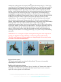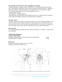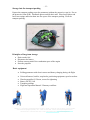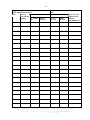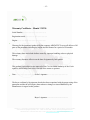
1
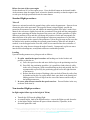
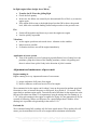
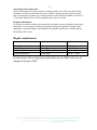
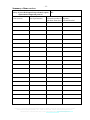
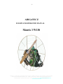
-1-
AIRGATECZ
FLIGHT AD OPERATIO MAUAL
Mantis 3 W130
Airgate cz, průmyslový areál Přerovských strojíren, objekt č. 6050-49, 750 00 Přerov, Czech republic,
Petra Ivanová (English speaker) Tel.: +420 777 810 328, e-mail: [email protected]
Jiří Kousal Tel.:+420 605 163 755, e-mail: [email protected], www.airgate.cz
-2-
SLZ Data – Mantis 3 W130
Registration mark
OK-
Inspector Technician
Registration book
Kind of
PPG
Landing gear
Engine
Propeller
ame
Firm
Serial umber
Harness
Standby
parachute
ame, type
Manufacturer
Serial umber
Year of production
Parachute glider
Take-off weight
Minimum
Maximum
PG o.1
PG o.2
PG o.3
PG o.4
Landing gear weight including accessories without fuel and fillings :
kg
Owner’s/operator’s data
Owner from - to
Operator from - to
ame/designation
ame/designation
Address
Address
Personal Ident. o.
Personal Ident. o.
Ident. o.
Ident. o.
Data about change of owner/operator
Owner from - to
Operator from - to
ame/designation
ame/designation
Address
Address
Personal Ident. o.
Personal Ident. o.
Ident. o.
Ident. o.
Signature of inspector- technician, stamp
In
Date
Airgate cz, průmyslový areál Přerovských strojíren, objekt č. 6050-49, 750 00 Přerov, Czech republic,
Petra Ivanová (English speaker) Tel.: +420 777 810 328, e-mail: [email protected]
Jiří Kousal Tel.:+420 605 163 755, e-mail: [email protected], www.airgate.cz
-3-
User manual for paramotor Mantis 3 W130
This manual has been issued by the manufacturer of SLZ. All records must be legible and
indelible. All pages must be included. This manual is a part of technical documentation.
Records of the total airtime and number of flights have to be kept in the new Flight Manual.
The last and obligatory bulletin is getting ready. Enter only verified and measured data into
technical – operational data. The manufacturer of SLZ, who is the owner of this manual, is
responsible for keeping records accurate and up to date.
EXPLANATORY NOTE: SLZ – abbreviation for sport flying machine
Important notice
If there are changes regarding regulations or the structure of SLZ, there will be a new
bulletin (for example in the PILOT) indicate these changes. Each owner is responsible to
make the change and mark this change in certain part of the manual.
The owner, each operator and the pilot must be acquainted with this manual.
This product is not subject to the approval of the Civil Aviation Authority of the
Czech Republic and is operated to own risk of the user. Intentional spins, falls and
acrobatics are prohibited.
All structural changes of the SLZ against the status, for which the technical certificate has
been issued, must be approved by the inspector-technician who has SLZ in his register.
Each damages of the SLZ must be reported to the given inspector-technician. He will
recommend the way of reparation; he will supervise the execution of reparation and will
perform a technical inspection after the reparation. The record is made in SLZ
documentation.
Operating of the directional controls and controlling of the SLZ
Aerodynamic control
The SLZ turns to the left side by pulling left hand side rope and it turns to the right side by
pulling right hand side rope.
The angle of the start of the canopy increases by pulling both control ropes simultaneously
and the flight speed decreases.
Inertial control
Once the pilot moves its weight in the seat to the left side, the SLZ turns to the left and vice
versa.
The SLZ turns to the right side being trimmed for the straight level flight at 50 % of the
engine power by increasing the speed.
The SLZ turns to the left side by decreasing the engine speed.
Change of pilot’s position and increase of the speed by means of speed system,
see fig. Flying positions a), b), c)
The SLZ is equipped with double cross-bar for control and steering by legs. The paramotor
unfold automatically itself into to flying position immediately after the start as a
Airgate cz, průmyslový areál Přerovských strojíren, objekt č. 6050-49, 750 00 Přerov, Czech republic,
Petra Ivanová (English speaker) Tel.: +420 777 810 328, e-mail: [email protected]
Jiří Kousal Tel.:+420 605 163 755, e-mail: [email protected], www.airgate.cz
-4consequence of the pressure of the pilot’s full weight in the harness (fig. A). Pilot’s legs
sustain in this basic flying position partly push forward in case of repeated contact with the
ground during the start or landing. A pilot moves his/her heel into the cross-bar number 1
(only in safe height) when he /she wants to turn the body to the aerodynamic preferable
position. A pilot change himself/herself into the horizontal position when he/she presses
with full power on the cross-bar by both legs. This position is fixed automatically by
moving gliders (on spacers) into ends of grooves. If a pilot releases cross-bar number 1,
his/her body get stabilised in flying position. (fig. B). A pilot can increase the speed of SLZ
by adding of cross-bar number 2 (speed system) and by pressing of both cross-bars
simultaneously. This causes decrease in angle of canopy and simultaneously turning of
pilot’s body into the horizontal flying position (fig. C). If a pilot wants to change his
position, he/she makes named steps in opposite direction. The speed of SLZ is decreased by
releasing of both cross-bars. This causes increase in angle of the canopy and
simultaneously turning of pilot’s body to the flying position (fig. B). When a pilot releases
the cross-bar number 2 and press the cross-bar number 1, he/she gets immediately in flying
and landing position (fig. A). At this time the tension is released in gliders locks of
spacers, a pilot can lock-off the safety-fuse by thumbs and a pilot move back gliders by
releasing cross-bar number 1 in its flying position (fig. A). A pilot is ready for the landing
manoeuvre.
WARNING!!! As a consequence of pilot’s turning and moving of the main snap hook of
the sling, the height of the sling will change as well as the position of the steering.
Therefore a pilot must pay the utmost attention to changed length of the steering, so that
the canopy is not stalled unintentionally!!!
Engine throttle control
The throttle control handle is positioned in the left hand. The power is increased by
depressing the lever and vice versa.
Ignition switch and starter button
The handle is equipped with two buttons. The red “switching off” button (at the thumb of
left hand) serves to shut down the engine. The black button “starter” serves to start the
engine. It is at the opposite end of the handle.
Airgate cz, průmyslový areál Přerovských strojíren, objekt č. 6050-49, 750 00 Přerov, Czech republic,
Petra Ivanová (English speaker) Tel.: +420 777 810 328, e-mail: [email protected]
Jiří Kousal Tel.:+420 605 163 755, e-mail: [email protected], www.airgate.cz
-5Fuel indicator and indication of the charging during a flight
The throttle handle is equipped with six LED diodes. Five diodes light when is the tank
fuel. Diode lights switch off one by one when the amount of the fuel decreases. When the
last diode twinkles, it signalises that there is enough fuel for last 10 minutes of a flight.
The six-diode indicates the process of the charging in this way:
-continual light: charging
-twinkled light: full charged battery
-light diode does not light: fault of the charging; in this case, a pilot has last 20-50 minutes
for the flight and landing (It depends on how the battery is charged).
The main switch
The rocker-type selector switch is placed on the upper cover of the ignition and battery. The
electronic ignition of the engine, fuel indicator and starting relay are started by turning on
the rocker-type selector switch. All function mentioned above are shut down by turning off
the rocker-type selector switch. By this is possible to shut down the running engine.
Rescue system
The standby parachute is positioned on the breast of the pilot in a container. It is thrown-off
by a right hand.
Technical parameters
Weight without fillings
Paramotor without harness, with electrical starter and propeller
Maximum take-off weight
23 kg
150 kg
Dimensions
Paramotor in transport packing 50 x 60 x 120 cm
Diameter of protective frame 135 cm
Airgate cz, průmyslový areál Přerovských strojíren, objekt č. 6050-49, 750 00 Přerov, Czech republic,
Petra Ivanová (English speaker) Tel.: +420 777 810 328, e-mail: [email protected]
Jiří Kousal Tel.:+420 605 163 755, e-mail: [email protected], www.airgate.cz
-6Engine
Two-stroke spark-ignition single cylindered W130, membrane carburettor Walbro,
tuned exhaust with extra silencer
Volume of cylinders
130 ccm
Max. take-off power
24 hp
Power unit weight, with electric self-starter
13,5 kg
Fuel
petrol 95 octane
Average consumption
2,5 l/hr
Oil (recommended for low speed engines)
filled synthetic
Mixing ratio
1 : 50
Ignition
processor
Reducer
1: 3,1
Fuel tank volume
11,5 l
Propeller
wooden Ø 120 mm
Electronic recharging during a flight
5A
Rescue parachute system
Type, producer
Way of activation
Max. sinking speed
at max. take-off weight
Positioning
Battery
Type
Capacity
Voltage
Ignition/ charging
Processor, without contact with gradual control
of the pre-ignition depending on engine speed
Energy consumption during running of the engine
Controlled charging current
Starting circuit
Starting current (to start only till 6 s, 15 s cooling)
Efficiency
ring / easy fly
manual
7 m/s
150 kg
on the pilot’s breast
NiCd
2.5 A/h
14,4 V
E-power
max 1 A
max 3,5 A
200A
98%
Pre-flight preparation
Assembling of the paramotor
Place carbon spacers into operational position after opening the transport bag and connect
spots of turning by mounting and tightening up the screw M6. Tightening up the screw M6
must let spacers freely turn around. When the motor is prepared in this way, take the motor
out of the transport back and put it on its bases. Handle beam of rays with strings and
Airgate cz, průmyslový areál Přerovských strojíren, objekt č. 6050-49, 750 00 Přerov, Czech republic,
Petra Ivanová (English speaker) Tel.: +420 777 810 328, e-mail: [email protected]
Jiří Kousal Tel.:+420 605 163 755, e-mail: [email protected], www.airgate.cz
-7connect them with the frame of the motor according colours. Insert arches of protective
ring of the propeller according to the colours in between ends of rays. Arrange the position
of strings and hang the ending hangings in the shape of L on spines of the frame of the
motor. Tighten strings by hanging tightening tubes into hooks.
Propeller
Position the propeller on the reducer with the middle hole on the distance ring. Place the
propeller flange and secure it by means of six fastening screws. Tighten screws by the
attached wrench in the cross direction by a moment of about 1 kg/m. (Do not damage the
propeller body by strong tightening.) Mount the propeller properly, i.e. its leading edge
towards the engine. It is recommended to rotate one turn of the propeller manually before
the start and insure in this way that the propeller is positioned correctly.
Harness and its adjustment according to a pilot’s height
The harness is equipped with carrying girths; see Fig. 1, 2 (red, green, yellow). All these
thrust of the harness are converged into the eye designed for connection with the canopy.
Red thrusts LP are interconnected by a belly girth, buckle and a trimming for tension of the
girth. The foot girths are executed in the same way. The shoulder girths with trimming
are interconnected by means of breast girth, buckle and a trimming for tension. A pilot is
fastened into the harness by shoulder girths and breast girths. Shoulder girths are designed
for carrying the paramotor on the ground. The breast and shoulder girths are adjusted so
that the carbon contact back is seated by its cut-out to shoulders and back of a pilot. And
consequently the weight of paramotor is distributed into shoulders and back. Then it is
necessary to tighten foot girths and adjust the tension of the green thrust, see Fig. 1. The
setting of the distance of the green thrust influenced directly the perpendicularity of the
propeller thrust in all flight positions of a pilot.
Fig. 1
Fig. 2
FLIGHT
FLIGHT
CROSS-BAR POSITION
Airgate cz, průmyslový areál Přerovských strojíren, objekt č. 6050-49, 750 00 Přerov, Czech republic,
Petra Ivanová (English speaker) Tel.: +420 777 810 328, e-mail: [email protected]
Jiří Kousal Tel.:+420 605 163 755, e-mail: [email protected], www.airgate.cz
-8The transverse girth of the trimming of the straight flight has to be released before the start
and landing! Tighten up the girth during the flight if it is necessary. The girth is for the
stabilization of the overturning moment of the propeller. This girth is buckled last and is
used for straight flight adjustment at various loading engine levels.
After attachment of a pilot to the canopy, move karabiners of the positioning system to the
eye of the canopy along with main carbines, see the figure.
Pre-flight inspection
Frame
Strings
Propeller
Engine
Reducer
Equipment
Tank
Seat
Rescue system
Oil
Petrol
Engine test
Pilot
Instruments
Parachute
entireness, assembly, securing
entireness, tension
orientation, tightening of screws, entirety
silent blocks, carburettor fastening, exhaust fastening
screws, belt tension
entire status, fuel inlet, electrical contacts, switches, spark-plug
cable
leak proof, cover tightness
connecting points, pilot, parachute
connection, locking pins, handle
correct mixture
sufficient fuel for the planned flight
high speed, idle run, switching-off
crash helmet, suitable dress and footwear, gloves
altimeter, rate of climb indicator - setting and checking of proper
function
canopy, ropes and loose ends
Engine test
ever start the engine without the propeller! Turn on the main switch placed on
the cover of the ignition.
Before the start of the cold engine
Set the throttle at the full power in that way that the constricting flap of the carburettor
opens. Enrich the mixture of the fuel by 3-5 multiple injection of the fuel with help of
pump on the cover oh the ignition. Set the throttle on 20% power. Press the black button on
the throttle handle. At this time, when the motor starts, release the throttle slowly to prevent
high speed of the motor and release the button of the starter.
Airgate cz, průmyslový areál Přerovských strojíren, objekt č. 6050-49, 750 00 Přerov, Czech republic,
Petra Ivanová (English speaker) Tel.: +420 777 810 328, e-mail: [email protected]
Jiří Kousal Tel.:+420 605 163 755, e-mail: [email protected], www.airgate.cz
-9Before the start of the warm engine
Set the throttle on 10% of the engine power. Press the black button on the throttle handle.
At the moment when the engine starts, release the throttle smoothly so that the engine is not
revved up to the high speed and release the starter button.
Standard flight procedures
Take-off
Spacers are oriented towards the ground when a pilot carries the paramotor. Spacers do not
restrain the pilot in his movement. The propeller thrust is sloped slightly towards the
ground at the moment of the run and enables the natural position of the pilot’s trunk. Once
unstuck, the reels move slightly forwards due to tension of foot girths and the pantographic
spacers start optimising the thrust direction of the power unit. All other positions of a pilot
influence positions of legs and this will change the position of reels and consequently the
thrust direction of the power unit. All this happens without any attendance of a pilot who
may pay his attention to the control of the paramotor. Unless the pilot steps on the cross-bar
he remains in the position enabling the repeated ground running. When the safe height is
reached, it can be stepped on the cross-bar, which is not connected into the accelerator of
the canopy (the wing does not change the angle of attack). Consequently a pilot can move
into the more advantageous, aerodynamic and more comfortable position.
Landing
Upon the landing manoeuvre a pilot proceeds as follows:
1. If a pilot stand in the speed cross-bar and bushings are locked in their end
position, a pilot has to:
a) Leave the speed cross-bar and move his/her legs to the positioning cross-bar
b) Press fully the positioning speed bar ( it is possible to land relatively safely
in the case of emergency with secured bushings at their end position, but it is
recommended to press fully the positioning speed bar for the right function
of the harness)
c) Release the thrust in trips of bushings, pilot can lock-off them by safety-fuse
by thumbs and in this way a pilot allows their come back to the starting and
landing position. Take out legs from the seat of the harness and be ready to
the landing manoeuvre.
2. In case a pilot does not stand in the speed cross-bar: Proceed further in the way
as shown under item b).
on-standard flight procedures
In-flight engine failure (up to the height of 200 m)
•
•
•
Transfer the SLZ into the gliding flight
At a small height, land in the flight direction – correct the flight to avoid obstacles
At the higher height, land into the space without obstacles, if possible, in the
direction against the wind
Airgate cz, průmyslový areál Přerovských strojíren, objekt č. 6050-49, 750 00 Přerov, Czech republic,
Petra Ivanová (English speaker) Tel.: +420 777 810 328, e-mail: [email protected]
Jiří Kousal Tel.:+420 605 163 755, e-mail: [email protected], www.airgate.cz
- 10 In-flight engine failure (height above 200 m)
•
•
•
•
Fire
•
•
Transfer the SLZ into the gliding flight
Check the fuel quantity
In the case the failure was caused by the discontinued flow of fuel, try to start the
engine again
If the engine fails to start or the height drops less than 200 m above the ground
level, then select a suitable landing surface and proceed as in the previous case
Switch off the ignition and do not try to start the engine once again
Land as quickly as possible
Vibrations
• set the engine speed into such mode where vibration are the smallest
• land as soon as possible
• if vibration increase, turn off the engine immediately
Application of rescue system
• Turn of the ignition in case of emergency upon definitive loss of control over the
parachute, grasp the releaser of the standby parachute, release it by pulling and
throw it askew from a pilot’s body in the direction of pilot’s rotation.
Adjustment and maintenance of power unit
Engine running-in
Engine running-in is very important because of two reasons:
1) proper settlement of all parts of an engine
2) decisive influence to the total service life of an engine
We recommend to let the engine run for about 1 hour on the ground at medium speed and
from time to time to increase the power to full speed for a period of 1-2 seconds. Then
return back to medium engine speed. Towards the end of this hour let the engine run at the
full speed for about one minute. It is important to keep the mixing ratio for running-in, i.e.
1: 30. After such running-in the engine is capable for flying. It is not appropriate to fly for
a period of following 5 hours at a full power for a period longer than 5 minutes. After
running-in it is possible to begin mixing in the ratio of 1:50.
Fuel and oils
We recommend using fully synthetic oils for lower-speed motors. These quality oils will
ensure you the maximum service life of an engine and its minimum carbonisation.
Airgate cz, průmyslový areál Přerovských strojíren, objekt č. 6050-49, 750 00 Přerov, Czech republic,
Petra Ivanová (English speaker) Tel.: +420 777 810 328, e-mail: [email protected]
Jiří Kousal Tel.:+420 605 163 755, e-mail: [email protected], www.airgate.cz
- 11 Tensioning of the reducer belt
Steps of tensioning of the reduce belt are: loosing up safety screw M6, turn with the help
of iambus screw the cracked shaft the wheel of reducer into the position when the reducer
belt is strained up in required way (with the pressure on the belt in the middle of wheels cca
5-7kg makes drop about cca 3-5mm), tighten up the safety screw M6.
Propeller maintenance
If you discover minor scratches on the propeller, treat them to prevent humidity penetration
into blades. It is necessary to balance the propeller during the reparation of larger cracks.
Applying of varnish and paints will unbalance the propeller and increase vibration during
the running of the motor.
Regular maintenance
Part
inspection
replacement
spark plugs
reducer belt
engine silent blocks
exhaust silent blocks
10 hr
before flight
before flight
before flight
50 hr / year
100 hr / 2 years
100 hr / 2 years
100 hr / 2 years
It is necessary to fix or change given part before the next flight in the case of
damage of any part of SLZ.
Airgate cz, průmyslový areál Přerovských strojíren, objekt č. 6050-49, 750 00 Přerov, Czech republic,
Petra Ivanová (English speaker) Tel.: +420 777 810 328, e-mail: [email protected]
Jiří Kousal Tel.:+420 605 163 755, e-mail: [email protected], www.airgate.cz
- 12 -
Summary of done services
Survey of prescribed inspections performed, repairs, OK replacement of important parts etc.
Action (reason)
Date of performance
Performed at number of Signature
flight hours flown (hrs.) executed/checked
Airgate cz, průmyslový areál Přerovských strojíren, objekt č. 6050-49, 750 00 Přerov, Czech republic,
Petra Ivanová (English speaker) Tel.: +420 777 810 328, e-mail: [email protected]
Jiří Kousal Tel.:+420 605 163 755, e-mail: [email protected], www.airgate.cz
- 13 -
Storage into the transport packing
Prepare the transport packing to put the paramotor (without the protective cage) in. Put on
the protective frame (OR). Dismantle spacers and tilt their ends. Place loose spokes and
bows into casings and insert them into free space of the transport packing. Close the
transport packing.
Principles of long-term storage
•
•
•
•
Drain out the fuel
Disconnect the battery
Perform conservation of the combustion space of the engine
Store the propeller
Basic equipment
• Folding paramotor with electric starter and battery charging during the flight
• Universal harness, buckles, snap hooks, positioning equipment, speed cross-bars
•
•
•
•
Wooden propeller Ø 120 mm, screws for tightening
Battery NiCd 2,5A/h
Transport packings
Flight and Operation Manual / Warranty certificate
Airgate cz, průmyslový areál Přerovských strojíren, objekt č. 6050-49, 750 00 Přerov, Czech republic,
Petra Ivanová (English speaker) Tel.: +420 777 810 328, e-mail: [email protected]
Jiří Kousal Tel.:+420 605 163 755, e-mail: [email protected], www.airgate.cz
- 14 -
Daily operation records
Date
Place of
Daily
take-off and
o. of take- Flight
landing
offs
duration
OK Total
o. of
take-offs
Flight
duration
otes as to the
flight, defects,
repairs,
consumption etc.
Airgate cz, průmyslový areál Přerovských strojíren, objekt č. 6050-49, 750 00 Přerov, Czech republic,
Petra Ivanová (English speaker) Tel.: +420 777 810 328, e-mail: [email protected]
Jiří Kousal Tel.:+420 605 163 755, e-mail: [email protected], www.airgate.cz
- 15 -
Warranty Certificate – Mantis 3 W130
Serial Number:…………………………………
Registration mark:……………………………….
Engine:…………………………………………
Warranty for the paramotor produced by the company AIRGATECZ covers all defects of all
parts of the paramotor including the engine and the harness for a period of 24 months.
The warranty does not include defects caused by improper handling or due to physical
damage.
The warranty becomes effective on the date of signature by both parties.
This product is not subject to the approval of the Civil Aviation Authority of the Czech
republic, and is being used to the own risk of the owner or operator.
Date……………………………Seller’s signature …………………………….
The buyer confirms by his signature that he has been acquainted with the proper using of the
paramotor and that he will inquire about whatever changes or issued Bulletins by the
Manufacturer in regard to this product.
Buyer’s signature...............................................
Airgate cz, průmyslový areál Přerovských strojíren, objekt č. 6050-49, 750 00 Přerov, Czech republic,
Petra Ivanová (English speaker) Tel.: +420 777 810 328, e-mail: [email protected]
Jiří Kousal Tel.:+420 605 163 755, e-mail: [email protected], www.airgate.cz