1
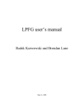
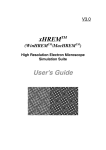
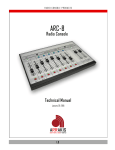
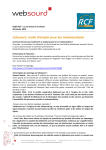
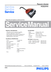
Domus.Cad 13 Release Notes
Domus.Cad 13
Release Notes
An outline of the differences between Domus.Cad 13 and Domus.Cad 12.
Domus.Cad 13 is for Windows 98/NT/2000/XP, Mac Os X and Mac Os 9
Interstudio S.r.l. all rights reserved
-1-
Domus.Cad 13 Release Notes
Table of contents
WHAT’S NEW...........................................................................................................................................................4
DOORS AND WINDOWS ........................................................................................................................................4
Tracing modes........................................................................................................................................................................... 4
Door/Window modify .............................................................................................................................................................. 5
Inside/Outside of openings ...................................................................................................................................................... 5
Type ............................................................................................................................................................................................ 6
Opening geometry .................................................................................................................................................................... 7
Reveals and sill parameters .................................................................................................................................................... 9
Minimum distance.................................................................................................................................................................. 11
DIMENSIONS .........................................................................................................................................................11
Selection of a dimension ........................................................................................................................................................ 12
Moving a dimension ............................................................................................................................................................... 12
Moving the dimension points................................................................................................................................................ 12
Deleting dimension points ..................................................................................................................................................... 13
Inserting dimension points.................................................................................................................................................... 13
Updating Dimension points................................................................................................................................................... 13
EDITING ELEMENTS.............................................................................................................................................14
Polygons, slabs and roofs....................................................................................................................................................... 14
Walls, Segments and Roofs ................................................................................................................................................... 14
MATERIALS ...........................................................................................................................................................15
Materials order ....................................................................................................................................................................... 15
Textures.................................................................................................................................................................................... 15
3D VIEW ..................................................................................................................................................................16
Selection ................................................................................................................................................................................... 16
Navigation................................................................................................................................................................................ 17
Standard Views ....................................................................................................................................................................... 17
View saving .............................................................................................................................................................................. 18
Textures.................................................................................................................................................................................... 18
3D View Keyboard Shortcuts ............................................................................................................................................... 18
3D Views and Palettes e Vista 3D ........................................................................................................................................ 18
ALIGNMENT OF SEGMENTS ..............................................................................................................................19
Alignment to a segment ......................................................................................................................................................... 19
Alignment to a Wall ............................................................................................................................................................... 19
Alignment on a Door or Window......................................................................................................................................... 20
Alignment on a Stair .............................................................................................................................................................. 20
Alignment on a Text............................................................................................................................................................... 20
Alignment on a polygon......................................................................................................................................................... 21
Alignment on a Floor/Roof ................................................................................................................................................... 21
EXTRUSION ...........................................................................................................................................................21
Multiple selection Extrusion ................................................................................................................................................. 21
WALLS JOIN, CUT AND FILLET .........................................................................................................................22
Join and Cut ............................................................................................................................................................................ 22
Fillet with arch ........................................................................................................................................................................ 22
Parabolic Fillet ........................................................................................................................................................................ 23
-2-
Domus.Cad 13 Release Notes
Fillet with given arch ............................................................................................................................................................. 23
TILE FILLS ROTATION .........................................................................................................................................23
3D VIEW OPTIMIZATION ......................................................................................................................................24
OTHERS FEATURES: ...........................................................................................................................................24
Safety back-up in Mac Os ..................................................................................................................................................... 24
Safety back-up in Windows .................................................................................................................................................. 24
Levels of Cancel (Windows)................................................................................................................................................. 24
Paging ....................................................................................................................................................................................... 24
Number of decimal points ..................................................................................................................................................... 25
Height of objects ..................................................................................................................................................................... 25
View end of Wall..................................................................................................................................................................... 25
Codes 30-characters long ...................................................................................................................................................... 25
Import graphic formats......................................................................................................................................................... 26
Calculation Codes................................................................................................................................................................... 26
Drawing preview..................................................................................................................................................................... 26
Polygon and slabs subdivision .............................................................................................................................................. 26
Opening documents with Alt and Command keys (Mac) ................................................................................................ 26
Zoom +/ – ................................................................................................................................................................................. 27
Metric calculation................................................................................................................................................................... 27
Walls intersection ................................................................................................................................................................... 27
Information palette ................................................................................................................................................................ 27
Fills Palette .............................................................................................................................................................................. 27
Materials palette ..................................................................................................................................................................... 28
Print fills .................................................................................................................................................................................. 28
3D View Quality...................................................................................................................................................................... 28
ObjRot Module ....................................................................................................................................................................... 28
-
-3-
Domus.Cad 13 Release Notes
What’s New
Below is a brief description of the differences between this version and previous version 12. For more detailed
information please consult the User Manual.
Doors and Windows
Some interesting improvements have been made to the Doors and Windows. Here’s how the new dialog Window for
Windows Parameters now appears:
Major innovations regard:
- Data input and modification
- New types for plans
- New types in 3D
- Parameterization of dimensions
Tracing modes
(a) Manual
Traditional mode (up till now, the only mode available).
A click of the mouse marks the beginning of a Door or Window. The end is marked when the mouse is released.
(b) Fixed distance from end
Select the option and insert the distance required, then click on the wall axis. The program selects the end of the wall
nearest to the click and puts the beginning of the opening at the distance required. The other end of the opening is fixed
in the traditional manner by dragging the mouse to the desired point.
(c) Fixed Width
The program draws the opening centered on the mouse click, with the width required. The opening can be dragged to
the position required.
(b + c) Fixed Width and Distance
-4-
Domus.Cad 13 Release Notes
The Door or Window is automatically centered in the Wall and its width is determined using the mouse. This works
something like ‘Tracing for the Centre’ except that in this option the program automatically decides where the
opening’s centre will be. The centre is found by finding the barycenter of the Wall’s shortest edge.
(d) Centered on the wall
A combination of options d and c. All you have to decide is the outside/inside of the opening.
(d + c) centered with fixed width
Click on a wall. The door/window will be positioned in the center of the wall.
(d + b) Centered with fixed distance
A combination of d and b options. As above, you only decide the outside or inside.
Some conventions used when tracing:
The above Tracing Modes work, unless you have selected the ‘Tracing for Center icon.
While tracing, you can, if wished, fix the mouse’s position to the Grid Points or other points in the drawing. Once you
have done this, the new snapped position is perpendicularly projected on the wall to set the end of the opening.
Door/Window modify
All the tracing modes above can be used to modify existing openings, regardless of how they have been inserted.
If an opening is selected, the current distance from end wall and width are shown, regardless of how the opening was
conceived.
Multiple selection is allowed, e.g. you can specify a standard width for all Windows.
Inside/Outside of openings
Tracing
While tracing with the mouse, a spot indicates the ‘inside’ of the Door or Window. This is valid for all tracing modes.
Selection
If you change the visualization mode while selecting the Door or Window, the ‘inside’ will be indicated by a small
square on the end of the opening’s central axis. This is particularly helpful for openings with straight reveals.
-5-
Domus.Cad 13 Release Notes
Modify
A new function enables you to invert the opening’s inside/outside. This is done, not through a Menu Command, but by
direct use of the mouse – you simply click on either end of the opening’s central axis.
(before)
(after)
Type
New types of opening are now available through the Menu ‘Type’,
or using the Attributes palette.
The number of type of openings is now 6. The first 3 were present in the previous version, The new types are:
-
Straight Niche
Inclined Niche
Invisible
The type can be chosen by the pop-up menu on the Door/Windows Dialog or using the Attribute palette.
Niches
-6-
Domus.Cad 13 Release Notes
Straight or oblique, they are contained by walls whose internal and external finish are chosen through the Dialog
Window.
Niches are positioned using the same modes as described above for doors and windows.
Invisible Openings
If the user has chosen a highly customized kind of opening, e.g. with curved reveals or protruding window-sills, it can
be useful to start from a totally empty space..
(Invisible Window)
Opening geometry
As well as the original rectangular shape, we have added several new forms to the Geometry Menu:
Rectangular
As in the version 12.
Arc
The arch is calculated automatically according to the width of the opening.
The example below shows two Windows of the same Height and Depth, but with different Widths; thus they form a
different height of arch.
The two windows below have same height and sill, but different width,
-7-
Domus.Cad 13 Release Notes
Lowered center arc
The two Windows have the same height and depth and, in this example, the same ‘height-of-arch’.
Lowered Arc
Similar to Lowered Arch. The openings have the same Depth, Height and ‘height-of-arch’, but different Widths. But,
while the Lowered Arch is done using a portion of circumference, the Flattened Arch uses a semi-oval curve.
Compare the figure below with the Lowered Arch above – note the sides of the Window run into the arch below
Circular arch (circle):
The Depth of the opening is taken into consideration, but not the Height, as the circle is calculated based only on the
Width.
In the example above, the two Window have the same Depth, but different Heights (diameters), because they have been
drawn with different Widths
Oval
The Depth or sill, together with the Height and Width, form a rectangle inside which an Oval is traced.
-8-
Domus.Cad 13 Release Notes
Reveals and sill parameters
The reveals data are totally editable, allowing you to resolve very complex situations.
Ticking the ‘Simplified’ box gives you the predefined parameters available in former Version 12 of Domus.Cad:.
• the window-sill is calculated at exactly half the width of the Wall and its inside edge runs along the Wall’s
barycenter
• the reveals are always 8 cm
• any splayed reveal is drawn at a fixed angle (so, the thicker the Wall, the wider the Door or Window opening)
The Simplified option produces a drawing as in Domus.Cad 12,
Depth of Window Sill
This allows you to define the depth of the window sill, irrespective of the Wall thickness.
The example below shows the ‘classic’ solution as per the former version of Domus.Cad the -window sill is half the
width of the wall, 5 cm.
Simplified
But with Version 13 you can reduce the sill to 3 cm :
10 cm Wall - 3 cm Sill
…or increase it to 8 cm.
10 cm Wall - 8 cm Sill
…and even if we widen the Wall to 20 cm, the window sill can remain at 8 cm.
-9-
Domus.Cad 13 Release Notes
20 cm Wall – 8 cm Sill
There is no limit to the maximum width of the window sill – it can even be wider than the Wall!
The possibility of the sill being wider than the wall is particularly useful for Doors and Windows set in a niche. We get
a sort of pillar which protrudes from the Wall, but can be modified just like a normal opening.
The following example shows, not a thicker Wall, but a Window in a niche with a 15cm window sill.
The possibility of ‘protruding’ window sills works with obliquely-set niches, too.
10 cm Wall – 15 cm “Sill”
Width of reveals
Different widths can be chosen for the left*- and right-hand reveals, as in the example below, where the left-hand reveal
is 15cm and the right-hand, 5 cm.
15 cm left – 5 cm right
The width of the reveal must always exceed zero, though it can go down to 0.0001 cm, as in the example below:
15 cm left – 0.00001 cm right
Splayed reveals width
As you can see in the example above, it’s possible to have a splayed reveal on one side and a straight reveal on the other
side. Not only, the splayed reveal width can be negative, as in the example below.
- 10 -
Domus.Cad 13 Release Notes
10 cm left – 0 cm right
5 cm left - - 5 cm right
Some notes:
By the combination of the various parameters it’s possible to create many types of windows and doors.
Minimum distance
The minimum distance of a Window/Door from the wall extreme is now 1 cm (2/5”). In the previous version it was 8
cm (3” 1/5).
Dimensions
You can now modify dimensions in interactive mode. Up till now, the elements which make up a Dimension (such as
Segments, Texts) were treated separately. With Domus.Cad 13, you can work on the Dimension in its entirety.
To deal with the separate components of a Dimension, use the Segment or Text buttons. As in the previous Version 12,
you can select, move and change the various elements as much as you wish.
- 11 -
Domus.Cad 13 Release Notes
To work on the Dimension in its entirety, use the Dimension button. (This new operating mode does not apply to
dimensions inserted using previous versions of Domus.Cad).
Selection of a dimension
Any click on one of the components of the dimension (text or segments), select all the dimension (all the text and all the
segments),
(before)
(after clicking on a segment or text)
Moving a dimension
Multiple Selection allows you to move the whole Dimension, keeping its axis parallel and its ends firmly ‘fixed’
between two lines drawn perpendicular to the ends. The Dimension Points remain unchanged.
NB: the above is true only when moving using the mouse; if you use the arrow keys, then the Dimension can be moved
in any direction, like any normal Multiple Selection.
During this operation, an Information Window gives interactive update on : X difference, Y difference, length and
angle. For X and Y, the difference is shown between the original coordinates and the present ones. ‘Length’ is the
distance between the two axes, calculated perpendicularly. ‘Angle’ is the axis angle (which however remains
unchanged during the move).
Moving the dimension points
Clicking on an individual dimension point allows you to move it up or down the axis, between the two dimension points
on either side. A dimension point at the end of the axis can be moved, on one side, as far as the next ‘internal’ point,
while the ‘free end’ can even be extended, thus increasing the original Dimension.
The coordinates are shown interactively, near the Mouse cursor. In the example below, the Attach Point being modified
is 127 from the point on its left and 154 from that on its right.
- 12 -
Domus.Cad 13 Release Notes
Deleting dimension points
Dimension Points can also be deleted using the Alt-Click, like Polygons can have their Vertexes cancelled. The
measurements are automatically re-calculated.
Inserting dimension points
New Dimension points can be added, using Ctrl Click (Win) Command-Click (Mac) on the axis (rather like inserting
intermediate Vertexes in Polygons).
Immediately the distance of the new Point are shown from the Points on either side of it.
Before
During
After
New Points can be added externally to the Dimension by first selecting the Dimension, then Ctrl- Clicking (Win) or
Command-Clicking (Mac) where the new Points are required.
Updating Dimension points
Following moving, deleting or insertion of new Dimension Points, the revised Dimension still keeps the original Global
Operating Parameters, such as Type of Decimal Rounding, Style of Text, Number of Decimals, Measurement Unit,
Length of Lines, Distance of Text and so on.
Our example below shows the original Dimension:
Now, not only have we moved one of the Dimension Points, we have also changed the Style of Text, Length of Vertical
Lines, Distance of Text, Unit of Measurement and also Number of Decimals.
- 13 -
Domus.Cad 13 Release Notes
(final result)
We could then change Type of Decimal Rounding :
(original situation)
(rounding to the nearest 5)
(rounding to the nearest 10)
Thus the parameters of the entire Dimension can be changed, following a change made to one of the Dimension Points.
Except for the color – the color used for the axis is applied, ignoring ‘Current Color’.
Editing elements
Polygons, slabs and roofs
There are two new buttons:
"Shift Vertices back"
e "Shift vertices forward"
:
These allow you to shift the vertexes ‘around’ the outside of the polygon or slab.
Practically the numbering of each vertex is shifted forward or backward depending on the button pressed.
The Buttons have been given a ‘+’ and ‘-‘ sign – marking them ‘clockwise’ and ‘anticlockwise’ is not feasible, as the
‘contorted’ nature of some Polygons make it impossible to forecast the direction Vertexes will shift in.
It is now easier to deal with OPEN Polygons – and also to change the direction of Textures (see below).
Walls, Segments and Roofs
There are two new editable fields: Distance and Angle.
- 14 -
Domus.Cad 13 Release Notes
Materials
Mac Os X
Windows XP
Materials order
It’s now possible to change the order of the materials.
The four buttons below change the order of the current material.
Textures
Any material can have an associated texture.
The Texture button opens the following Texture Parameters Dialog:
Mac Os X
Window XP
- 15 -
Domus.Cad 13 Release Notes
Clicking on the Texture files, a pop-up menu allows the user to choose a texture. A preview of the chosen texture is
immediately shown.
“-“ and “+” buttons zoom out and in the preview.
“100%” shows the texture with its real dimensions.
Height and Width fields are the real dimensions of the texture. If the box on the right is checked, the real dimensions are
forced to be proportional to the texture pixels dimension.
The Angle field rotates the texture with reference to the horizontal default direction,
The default 0 direction is as follows below:
-
Walls: base line.
Floors and Roofs: first side
Stairs: steps width
Repeat X: if checked the texture is repeated in the X direction.
Repeat Y: if checked the texture is repeated in the Y direction.
X and Y offsets allow the user to perfectly align the texture with the element geometry.
If X and Y are 0 and Repeat X and Repeat Y are deactivated, the texture is applied in the left bottom corner of the
surface.
The texture can be enabled or disabled by the Enable check box in the Materials Dialog Window.
A button on the 3D View activates or deactivates the visibility of all the textures in the 3D View.
To insert new user textures simply insert images in the DOMUS-Cad Data -> DOMUS-cad textures folder. Some of the
supported formats are jpeg, tiff, gif, BMP, Targa, PNG and others.
Some examples of a texture applied to a wall follow below:
Texture not repeated
Repeated along X
Repeated along X and Y
Rotated
At present RayShade Renderer doesn’t support textures which are not repeated.
Quesa (Mac Os X) partially supports repeated textures,
QuickDraw™ 3D (Mac Os 9 and Classic) support all the modes.
3D View
On the bottom of the 3D View there is a new palette with new commands and operative modes,
Selection
The first button activates the Selection Mode.
Clicking on an element on the 3D view selects the element in both 3D View and plan window,
• The selected element is highlighted with handles on the corners. If the element is an object, it’s highlighted inside a
multicolored wire frame;
- 16 -
Domus.Cad 13 Release Notes
Selected element
Selected object
• Shift –clicking on others elements adds them to the current selection;
Multiple selection
• Shift-clicking on a selected element deselects it.
• Usually it is possible to select the active layer elements only.
• Command-clicking on a element selects it independently of the layer of the element. If it is different from the current
layer, that becomes the element layer.
• Double clicking on an element open the Parameters Dialog of that element. It is possible to change all the parameters
of the elements directly on the 3D View.
• Double-clicking on an element with a layer different from the actual layer changes the actual layer and opens the
Parameters Dialog of the element,
Navigation
This button enables the Navigation mode (as in the previous Domus.Cad versions).
Standard Views
There are 6 standard views.
Front View. The Camera looks in the Y direction.
Left View. The Camera looks in the X direction.
- 17 -
Domus.Cad 13 Release Notes
Back View. The Camera looks in the -Y direction.
Right View. The Camera looks in the- X direction.
Panoramic View.
Centered View. The Camera isn’t moved and the observed point is moved exactly to the center of the 3D model.
View saving
Copy View. The 3D view image is copied on the Clipboard.
Copy View on a Layer. The 3D view image is copied to a chosen layer.
Save 3D View as 3D Metafile.
Textures
Enable and disable the visibility of the textures.
3D View Keyboard Shortcuts
Key
A
D
F
S
T
Function
3D model "Autoscale”
Navigation mode
Front View
Selection mode
Textures activate/deactivate
3D Views and Palettes e Vista 3D
Now the palettes are active even if the 3D View is the front Window.
This allows the user to apply the palettes command to the selected elements on the 3D View, see below some examples:
- Change the active layer;
- Group a multiple selection to an object.
- Separate one or more selected objects
- Select a slab and click on the Generate Walls on slab command.
- 18 -
Domus.Cad 13 Release Notes
Alignment of segments
This new command, on the Palette n. 2, allows the user to cut or elongate selected segments on a chosen element.
This command is similar to the Join and Cut command. The Join and Cut command can be applied to two segments or
walls, while the Adapt Lines to Alignment command can be applied to a multiple selection of segments.
Selection of the segments
After executing the Segments Alignment command
After choosing the option the cursor changes to:
, to remind you to chose an alignment element. The user can
choose any element with the exceptions of objects and images. The program then:
1) • finds the intersection between the Line and its new alignment (if necessary, by projecting the Lines and the
alignment-line until they meet)
2) • chooses the end of the Line nearest the Alignment
3) • extends or cuts the Line at the intersection mentioned in point (1)
The below example shows how it works:
Before
After
Alignment to a segment
The alignment reference line is the axis of the segment.
Alignment to a Wall
Segments are aligned either right or left of the Wall, depending on their ‘prevailing’ position.
- 19 -
Domus.Cad 13 Release Notes
Before
After
Alignment on a Door or Window
As for Walls, both sides of the Openings are used.
Before
After
Alignment on a Stair
As for Walls and Openings, the two sides of the staircase are used:
Before
After
Alignment on a Text
The alignment is made to the base line of the text:
Before
After
- 20 -
Domus.Cad 13 Release Notes
Alignment on a polygon
Polygons, and also Oval, Circles, Arches and freehand Curves. Click beside the edge you want to use for alignment. It
will then appear as a heavy line.
The alignment line is the axis of the side clicked on:
Prima
Dopo
Alignment on a Floor/Roof
As above.
Extrusion
The Extrusion dialog window has additional new parameters:
Reference Height: The reference height of the generated extruded object (on Domus.Cad 12 it was always 0).
Use slab thickness: currently selected slab thickness is used. If none, the slab thickness equals zero (in practice, a
surface).
Use slab colors: currently selected slab colors are used. If none, the current color is used.
Multiple selection Extrusion
Now the Extrusion command can be applied to a multiple selection, in fact, the name of the option is now in plural
form: Extrude Slabs from Polygons
Until now, to extrude a Slab from complex forms with holes punched out of them, it was necessary to first create one
single Polygon. With Version 13’s Multiple Selection Extrusion, all you do is bring the various Polygons together, as in
the example below:
The extrusion result is:
- 21 -
Domus.Cad 13 Release Notes
Walls Join, Cut and Fillet
All the Join, Cut and Fillet commands, that in the previous version were applicable to segments only, are now
applicable to walls.
Join and Cut
The Walls must be selected exactly. Then click on the following buttons (choose either Join and Cut
and Eliminate
or Join, Cut
), or use the Join and Cut Command from the Edit Menu.
The option must not be used on Walls containing Openings.
1) Join and Cut:
Before
After
2) Join, Cut and Eliminate:
Before
After
Fillet with arch
Either press
, or select Link with Automatic Arch, from sub-menu Automatic Generating, in the Edit menu. Again,
the two walls must be selected exactly.
When you link Lines, you get one single Element, a Polygon. But when you link Walls, the program generates
internally a temporary polygon (later cancelled), on which builds a succession of little Walls. As this temporary
polygon is created along the axes of the two selected Walls, axial tracing is also used to build the Walls of the arch.
You can use the temporary polygon to operate on the precision of the new walls, by modifying Maximum Vertexes for
Polygons in the Polygon Dialog Window.
- 22 -
Domus.Cad 13 Release Notes
Before
After
Before
After
Parabolic Fillet
Works same way both for Lines and for Walls – press
Automatic Generating, in the Edit menu.
or select Link with Parabolic Fillet, from sub-menu
For further information, see above explanation for ‘Fillet with arch’.
Fillet with given arch
Works same way both for Lines and for Walls – press
Automatic Generating, in the Edit menu.
or select Link with Arch and Radius, from sub-menu
For further information, see above explanations for ‘Fillet with arch’ and ‘Parabolic Fillet’, except for following
difference:
-
when the two selected Walls are joined by the new section of Arch, a re-fusion also takes place at the other two
ends of the Walls concerned. Now, if one of the ends already contains a fillet with arch (and therefore has a
minimal ‘Maximum Attach Distance’, there is a possibility you may get unwanted fusions between the original
Wall (which undoubtedly had an ample Maximum Attach Distance) and some very short walls (see example
below):
before
after
magnified view of the ‘unwanted fusions’
This problem can only arise when using the Fillet with Given Arch Command – never with the Fillet with Arch or
Parabolic Fillet commands.
How to solve it? Specify a low value for Maximum Attach Distance, at least for the Wall which shows the problem. In
our example, the left-hand Wall has been given an Attach value of ONE centimeter.
As you can see, there are no unwanted fusions.
Tile Fills Rotation
The Angle parameter on the Tile Fills parameter windows is now active. It’s possible to create new fills rotating the
tiles as in the example below:
- 23 -
Domus.Cad 13 Release Notes
3D View optimization
The 3D Interactive View is strongly optimized, for faster 3D View updating after any model change,
The model is divided in many groups, one for each layer and one for the lights.
When an element is added or edited, only the active layer is affected, so it’s sufficient to update only a part of the model
(instead of the whole model as in the Domus.Cad 12 version).
If the 3D updating slows down, it is recommendable to subdivide the layer to two or mode layers.
Others features:
Safety back-up in Mac Os
You can always recuperate the penultimate version of your Drawing!
When you come to save the version you have just finished working on, the Save to Disk Command:
a)
first saves the new version to a temporary file called DOMUS-cad.file.provv. in the DOMUS-cad Data
personal folder
b)
if the Save operation is successfully completed, the new and old versions are swapped over (the old
version over-writes any previous version already in DOMUS-cad Data
c)
the penultimate version is safely parked in DOMUS-cad Data, until over-written by the next Save
operation.
Safety back-up in Windows
The Save to Disk Command saves the current version and also creates, next to it, a re-named copy of the previous
version, in the BackUPDomus folder. In BackUPDomus, you have a sub-file called NameofProject.Dir, which contains
the last ten versions of your project, named Back_NameofProject.WorkTime.dms.
These are regular Domus.Cad files and can be opened, modified, saved, etc.
Levels of Cancel (Windows)
You can now deactivate Undo/Redo by choosing Level 0 In the Undo/Redo Preferences dialog window. This Is
particularly useful when Importing documents with a lot of elements (e.g. maps In .dxf) and when your memory Is
limited. Just cancel the parts you don't want and Import faster.
Paging
Before, a mouse-click would automatically select the Component highest-up on Domus.Cad’s internal listing of
Components for Paging. If you were unlucky and this first component was a frame around the page, you were unable
then to select anything else on the page!
But now:
- 24 -
Domus.Cad 13 Release Notes
-
if a Component is already selected, the Mouse choose it, without searching for the first Component memorized
clicking on a Component different from the selected one results in a search, where the program will always
propose the first Component on the internal list, however you can choose another Component via Menu
clicking outside of all Components cancels all selections
Number of decimal points
The following modifications have been made:
• In all Dialog Windows and Palettes, angles are shown with four decimal points
• In the following Dialog Windows and Palettes:..
-
Coordinates Palette
Offset Parameters Dialog Window
Dialog Window for editing ‘static’ Elements
Dialog Window for editing ‘dynamic’ Elements
Decimal points shown for numerical values depend on the unit of measurement chosen, e.g. for millimeters = 2
decimal points, for centimeters = 3, for meters = 5, for kilometers = 8 decimal points.
• In the Stairs Parameters Dialog Window, the tread is shown with an automatically defined number of decimal
points, in the same way as described above
• The Information Palette shows the number of decimal points you have specified – plus one. That is, if you
specified, for your unit of measurement centimeters, no decimal points), the Information Palette will show all values
with one decimal point.
Height of objects
The height shown in the Dialog Window refers only to Objects created in Drawing mode. Objects created using
Selection are given a height of 0, thus avoiding knock-on modifications to the position of other Elements.
Line of Cut
Now, if you press Shift while tracing the Line of Cut, the Line is forced into a horizontal or vertical position. You can
press Shift as often as wished, during tracing, to block or unblock the horizontal/vertical position.
View end of Wall
In previous versions of Domus.Cad you could make the ends of Walls visible or invisible, by doing Alt + click on the
wall end. Now you can do more!
By clicking on the
icon and then on the wall ends, not only can you choose if ends should be visible or not, but
you choice is now permanent (i.e. it remains the same, even after – for example – fusion of walls has taken place).
During this option, the cursor changes to:
.
Codes 30-characters long
Instead of the original 13 characters, you now have 30 available for the following:
• AREF codes for all Elements
• Names of Materials
• Names of Fills
- 25 -
Domus.Cad 13 Release Notes
• Category definitions
• Sets definitions
Import graphic formats
The Command Import PICT will now import all graphic formats recognised by QuickTime, including: jpeg, GIF, TIFF.
BMP, PNG, Targa and many more.
The results can be viewed in Print Preview – from there you can save the PICT in the above-mentioned formats.
Calculation Codes
You can now work on an Element’s Calculation Code, without involving the Category Code. You will find the new
Calculation Option in the Parameters Menu. The Dialog Window shows the ‘type’ of Element you are working on – in
the example below, we have a Line…
Domus.Cad deals separately with a series of Calculation Codes for each of the following types of Element:
- Walls
- Doors and Windows
- Lines
- Texts
- Slabs and Roofs
- Stairs
- Polygons
- PICTures
- Objects
..so your criterion for calculating a Line could be Length, for a Polygon, Single Surface, for a Wall, Both Surfaces, for
an Object, Content – and so on.
Drawing preview
In creating a Drawing Preview the program now automatically converts to ‘Natural Scale’, thus avoiding the risk of
saving on disk a hugely-enlarged view, with consequent creation of an over-sized PICTure – and a "NewGWorld
Error" message.
Polygon and slabs subdivision
The Divide With Attach Points command, previously valid for segments and walls, is now applicable to polygons and
slabs.
Selected polygon
each side is subdivided in four parts
Opening documents with Alt and Command keys (Mac)
A safety check has been added when opening documents. Now, if you hold down Command or Alt, the 3D view
Window does not open, the interactive update function is de-activated, as is the Texture function. This makes it easier
- 26 -
Domus.Cad 13 Release Notes
to open complex documents, with lots of Textures, even on slower computers, should the Document have been filed
with Textures open.
Zoom +/ –
These commands have been modified, so that, even if you press Alt at the same time, the scale is enlarged or reduced
only by 10%, instead of 100%!
As you see the resulting change immediately, this makes it easier for you to find the ideal scale interactively (you no
longer have to key in your ‘guess’ of the desired scale in ‘Choose Scale’).
Metric calculation
Each column has, as before, space for 13 characters. For numbers/codes exceeding 13 characters, the first 12 characters
are shown, plus ‘..’ to indicate the elision – example below :
• Layer: 1 • <Layer 1>
============================================================================
Type
AREF
Categ.
Set
Material
Calc.
---------------------------------------------------------------------------Line
123456789012…
black
num
Line
short aref
short categ. Short set
black
lun
Line
123456789012… 123456789012… 123456789012… 123456789012… lun
Long codes are elided only when you Visualize on video or Save in Text Format.
If you Save in Table Format (fields separated by tabs), no elision takes place.
If you select ‘Consider only Visible Layers’ or ‘Consider only Active Layers’, the name of the Layer is now printed:
=====================================================================
CALCULATION
=====================================================================
• Layer: 31 • <FIRST FLOOR WALLS>
=====================================================================
SUB-TOTALS (by Category)
=====================================================================
Category: POROTON
length
: 93,82 m
Category: STONE
length
: 10,20 m
Category: BRICKS
length
: 67,77 m
Walls intersection
The Intersection Point command is now available also for walls, the intersection occurring at the walls’ axes.
Information palette
The height of selected objects is now shown.
Fills Palette
The Fills Palette always shows the name (and position) of current fill. If the fill is an angled tile, in the palette the fill is
edged in green and its angle is shown next to its name.
- 27 -
Domus.Cad 13 Release Notes
Materials palette
In the Materials palette the name of the current material can be seen.,
Print fills
In the Fills Parameters Window, you can now activate ‘Always use Mixed Format when Printing’. This overrides ‘No
format’, ‘BitMap format’ or ‘Normal Format’ in the Dialog Window. This function is particularly useful for Drawings
with a multitude of complex Vectorial Fills which can slow you down considerably.
In such situations, the temptation was to de-activate the Fills completely (or visualize them all in BitMap). And after
completing a lot of elaborate graphic work, to your horror, you realized you had hit the Print command, without reactivating ‘Print in Mixed Format’ …!
Now,this new function allows you to relax, work as much as you like without Fills – and still be sure that the Fills will
be printed in their correct format.
3D View Quality
For the moment, this choice is possible for arched Doors or Windows, but in future the choice will be extended to
Meshes and other elements.
‘Low’ quality defines an Arch with 10; ‘Medium’ quality has 25 parts ; ‘High’ quality has 60. Naturally, higher
quality definition takes longer to load.
ObjRot Module
This new module allows you to rotate a selected object, by inserting :
-
Angle of rotation in sexadecimals degrees (integer number)
Axis of rotation (X, Y or Z)
Rotation on the Z axis corresponds to the object rotation you have in the Process menu.
It is the Slabs which are actually rotated – all other elements remain in position. Should you want to rotate objects suce
as Walls, Stairs, etc., they must first be converted into two dimensions (slabs with 0 thickness).
The original object is not moved – the module creates a new rotated version, which you position using the space bar.
- 28 -