1
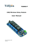
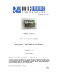
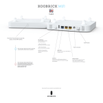
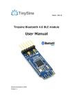
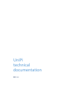
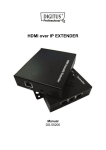
TOSR-04-5
TSIR04
USB/Wireless Relay with Inputs Module
User Manual
Tinysine Electronics @ 2014
Version 1.0
www.tinysine.com
INTRODUCTION
TSIR04 is a relay module with optically isolated inputs and OLED display and temperature
sensor port. Very powerful and easy to use. The communication module are replaceable.
USB/Bluetooth/WiFi/Zigbee are supported. We provide free test program and smart
phone APP. You can use your computer or smart phone control this relay easily.
The TSIR04 provides four volt free contact relay outputs with a current rating of up to
10Amp each. The module is powered from a 5V(12V) DC power supply. The DC input jack
is 2.1mm with positive core polarity, The relays are SPDP types.
SPECIFICATIONS
•
•
•
•
•
•
•
Number of Relays:4
Rated voltage:DC 5V and 12V version
Relay switching maximum power:10A 250VAC
Baud rate:9600
Communication Port:USB/Wireless
Support Xbee/Bluetooth/WiFi Control
Supply voltage:5V/12V DC
IMPORTANT DISCLAIMER
This device connects to the USB port of your computer and can be used to control
external devices connected to its onboard relays. Incorrect wiring or shorts on the board
can potentially cause damage to the controller itself, your computer's USB controller
and/or your computer's motherboard if an external voltage make its way to the USB bus or
the USB port is shorted. Extreme care must be taken when using this device to avoid any
damage to your equipment. In particular, make sure you always disconnect the device
from the USB port as well as any other power source when working on the device.
Tinysine Electronics, it's shareholder,employees,suppliers,distributors and/or resellers are
not liable for any damage or loss of data as a result of the use of this device, including
special,incidental,or consequential damages resulting from the use of this device,or under
any legal theory,including lost profits,downtime,goodwill,damage to or replacement of
equipment or property,and any costs or recovering or reproducing any data stored in
computers connected to this device.
Your use of this circuit indicates your acceptance of these terms
www.tinysine.com
Module overview
Optically Isolated Inputs
TSIR04 has 4 optically Isolated input ports. Input voltage absolute Max. 30v DC,
Operational 4.5v to 27v DC. TSIR04 has 2 working modes:
Normal mode:
When the board read a input signal. Reporting the input state.
Auto mode:
When the board read a input signal. Reporting the input state and turn on the
corresponding relay. When the input voltage removed, relay turn off.
OLED display
OLED display show the current board state. You can check the state no need connect it
with you PC.
www.tinysine.com
Current mode:
Manual/Auto
IN1:0/1
RLY1:ON/OFF
IN2:0/1
RLY2:ON/OFF
IN3:0/1
RLY2:ON/OFF
IN4:0/1
RLY3:ON/OFF
Temperature:
xxx °C
Temperature monitoring
TSIR relay have a DS18B20 temperature sensor port. You can use it read the realtime
temperature.
Operating temperature range: -55°C to +125°C (-67°F to +257°F).
Wiring:
red (VCC), yellow(DATA) , green(GND)
Relay power rating
If the relay is used at a voltage or current exceeding this specification, the life of the
contacts may be significantly shortened.
A full datasheet for the relays used on the TSIR04 is here: G5LA datasheet
Commands
www.tinysine.com
This module operates with an easy to use command set as described in the table below.
www.tinysine.com
How to use
USB Control Mode:
Step1:Intall the Driver
This module uses CP2102 USB to UART chip . Before use it you will need to download
the CP2102 Driver.
Connect the module to computer and windows will detect it and ask for the drivers. Point
windows to the inf folder and it will install the driver.
A new com port will now appear.
www.tinysine.com
Step2:Run HyperTerminal
The TSIR relay module is controlled using serial command. We use HyperTerminal
provided with Windows, but your favorite terminal should work fine. Be sure to set the
communication speed to 9600 8-N-1 and disable Flow control. Connect the module to
computer with USB cable, open the port and send test command you will see the relay on
or off.
www.tinysine.com
COM Port Setting
Send ASCII ‘d’->All relay on
Send ASCII ‘n’-> All relay off
Step3:Test Program
To get the TSIR up and running in the minimum amount of time we have put together an
example test program to demonstrate the functionality of the module
www.tinysine.com
www.tinysine.com
Wireless Control Mode:
Bluetooth Remote Control
The Tinysine Bluetooth Bee V3 is a Smart Ready Bluetooth wireless module. Which
means it can works with any version Bluetooth device. It can works with both android and
iOS. It has compact size and the pinout
is compatible with XBee which is suitable for all kinds of microcontroller systems who hav
e 3.3V power out, the module can use the AT commands to set baud rate.The Bluetooth
Bee module comes with an onboard antenna, the antenna provides better signal quality. I
t acts like a transparent serial port, which works with a variety of Bluetooth adapter
and Bluetooth phone.
www.tinysine.com
Step1: Power the Relay board
There are two versions of TSIR relay(5V/12VDC). Power your TSIR relay with correct
voltage. “PWR” LED lights up. “STATE” LED on the Bluetooth Bee slow blink.
Step2: Install TSIR Bluetooth APP
Andorid APP:
We provide Andorid .apk file directly. You can download or copy it to your Android
smartphone and install it directly. Download
www.tinysine.com
Bluetooth V3 module is are dual mode Bluetooth module.Click Menu->“Connect device”.
You will find a Bluetooth BLE device(00:0E:0B:XX:XX:XX) and a Bluetooth EDR
device(00:0E:0E:XX:XX:XX). Here we use Bluetooth EDR. And you can rename your
relay board.
Default password:1234. Once it connected. “STATE” LED solid on. You can turn ON/OFF
the relay. Monitoring the input&temperature.
www.tinysine.com
Click the temperature value switching the Fahrenheit and Celsius display. Switching the
working mode. Let the relay output associated with input.
iPhone APP:
Search “TSIR” in the APP store. Or visit install page directly. TSIR Bluetooth
www.tinysine.com
Click “Connect Device” to searching the BLE device. Select and connect it. “STATE” LED
solid on.
You can turn ON/OFF the relay. Monitoring the input&temperature. Click the temperature
value switching the Fahrenheit and Celsius display. Switching the working mode. Let the
relay output associated with input.
www.tinysine.com
WIFI Remote Control
The WiFiBee module is based upon Roving Networks' robust RN-171 Wi-Fi module and
incorporates 802.11 b/g radio, 32 bit processor, TCP/IP stack, real-time clock, crypto
accelerator, power management unit and analog sensor interface.The module is
pre-loaded with Roving firmware to simplify integration and minimize development time of
your application. In the simplest configuration, the hardware only requires four
connections (PWR, TX, RX and GND) to create a wireless data connection.
Step1: Install TSIR WiFi APP
Andorid APP:
We provide Andorid .apk file directly. You can download or copy it to your Android
smartphone and install it directly. Download
iPhone APP:
Search “TSIR” in the APP store. Or visit install page directly. TSIR WiFi
www.tinysine.com
Step2: Configuring WiFiBee module
There are 3 ways to configure the WiFibee module.
Use APP to configure it
1. Plug your WiFibee module into the wireless socket. Set the mode from “Normal->AP”
and then power the TSIR module. WiFibee creates a new WiFi network which named
'WiFly-EZX-XX'. The LEDs on the WiFibee will blink in sequence.
2. Let your smartphone join this 'WiFly-EZX-XX' WiFi Network. WiFibee D1 slow blink, D3
fast blink.
www.tinysine.com
3. Open TSIR WiFi APP. Clink “Configure” and follow the steps give your relay a
name->Input your home WiFi SSID->Input your home WiFi password->assign a valid IP
address for your relay board->Click Start.
4. Power off the TSIR relay board and set the mode switch back to “normal”. Power it up.
D1 slow blink, Means it already joined your home WiFi Network.
5. Let your smartphone join your home WiFi Network. Restart the APP. Connect
device.Then you can control the TSIR.
www.tinysine.com
Use configure tool program
If you have a USB adapter in hand. You can set the WiFibee by serial port. We provide a
WiFibee Setting tool program. Very convenient to use.
Simple 6 steps:
1.Plug your WiFibee or Wifly on your USB adatper
2.Connect the USB adatper to your computer.
3. Install FT232RL drivers. A new COM port will appears in the device manager.
4.Open the WiFibee setting tools.exe. Select the correct COM port.
5.Input your network SSID, Password, and assign a valid IP to the WiFi module.
6.Click writing configuration. All done!
After configuration. Your WiFibee module should joined your wifi network. D1 slow Blink. If
you want reset the module to factory setting. Just click "Factory Reset" button.
Send AT commands
Plug your WiFibee module into the wireless socket. Set the mode from “Normal->AP” and
then power the TSIR module. The LEDs on the WiFibee will blink in sequence.
*The WiFibee module will entering soft AP mode. Default IP is 1.2.3.4:2000,4.3 version firmware Default
IP is 192.168.1.1:2000
www.tinysine.com
Please refer the following steps to configure your wifly module.
1. Set your computer Obtain an IP address automatically.
2.
From your computer, You will find a new wireless network named Wifly-EZX-XX.
www.tinysine.com
Connect to the WiFly-EZX-XX network. This is an open network that does not require a
pass phrase or pass key.
NOTE: It may take a couple of minutes for Auto IP in Windows to assign an IP address
and connect to the network. You can check IP address of your Windows computer by
running the ipconfig command in the command window. If connected, this command will
show you the IP address and net mask for your computer.
The IP address assigned by Auto IP must be on the subnet 1.2.3.x subnet otherwise the
Wifly module will not be accessible.
NOTE: If your machine has both wireless and wired interface hardware you may need to
disable the wired LAN interface hardware before connecting to the adhoc network. If the
wired LAN is enabled, the computer may assign an IP address that is not on the same
subnet as the Wifly module.
3. Run HyperTerminal and create a new connection.
www.tinysine.com
AP mode
Telnet into the Wifly WiFi module on port 2000 telnet 1.2.3.4 :2000 / 192.168.1.1 (4.3
version firmware)
Once connected and you have a good IP address. You should see the response *HELLO*
Type $$$ (without hitting return) to enter command mode. Now you can setup the
module’s wifi settings (hit return after each command):
set wlan phrase <your wpa password>
set wlan ssid <your ssid>
set wlan join 1
www.tinysine.com
save
*Our test network ssid is Tinyos3f. Wlan phrase is 0000000000
And if you want a fixed IP address. Here is the command:
set ip a <your IP>
set ip dhcp 0
set sys printlvl 0
save
reboot
www.tinysine.com
Here we set our WIFI module IP address: 192.168.1.185
If we use a smart phone APP to control this relay module. When the phone out of WIFI
signal area may cause dead connection. We need to closing the TCP connection in this
situation. Here is the setting command. It’s important.
set comm idle 5
save
Reboot
Power off the TSIR relay board and set the mode switch back to “normal”. Power it up. D1
slow blink, Means it already joined your home WiFi Network.
If you want set the WiFiBee module to factory setting:
factory RESET
save
reboot
More details about wifly module please download the user manual.
Step3: Control your Relay
www.tinysine.com
Click “Connect Device” to connect your WiFi relay board. Once it connected. D1 solid on.
D2 fast blink.
You can turn ON/OFF the relay. Monitoring the input&temperature. Click the temperature
value switching the Fahrenheit and Celsius display. Switching the working mode. Let the
relay output associated with input.
Tinysine Electronics
www.tinysine.com
Email: [email protected]
Telephone: +86-551-65365921 Ext 801
Fax: +86-551-65365931
4-3 Hui Gu Park, Hai Tang Road, Hefei, Anhui, China