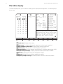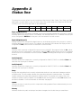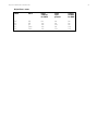
1
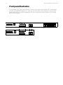
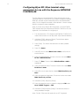
76
Response NETWORK CONTROLLER
Appendix B
Status LEDs
The front panel of the Response NETWORK CONTROLLER has a row of nine LEDs labeled +5, and A
through H. The LEDs indicate whether power is on or off, and the status of the controller’s inputs,
outputs and active memory.
Power
LED +5
On
Off
Power On?
Yes
No
Memory status
LED A
LED B
On
Off
Off
On
Problem with
memory
Yes
No
AMX Input status
LED C
LED D
Port enabled
for AMX
Valid input
present
Off
On
Off
Off
Off
On
No
Yes
Yes
No
No
Yes
Digital Port 1 status
LED G
LED H
Input
enabled
for DMX
Valid
input
present
Output
enabled
for DMX
Off
On
Off
On
Off
Off
Off
On
Flash
Flash
No
Yes
Yes
Yes
Yes
No
No
Yes
No
Yes
No
No
No
Yes
Yes