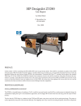
1
Primer Chapter 3 Capturing and Editing Digital Images* Revision 2005-06-16 Table of Contents 3.1 Introduction .......................................................................................................... 2 3.2 Scanners .............................................................................................................. 2 3.3 Capturing Digital Images by Scanning ....................................................................... 3 3.3.1 Determining Scanning Resolution ..................................................................... 3 3.3.2 Tonal Adjustments ......................................................................................... 5 3.4 Capturing Digital Images by Digital Photography ........................................................ 6 3.4.1 Megapixels.................................................................................................... 7 3.4.2 Digital Cameras ............................................................................................. 9 3.5 Digital Image Editing ...................................................................................... 10 3.6 Color and Tonal Adjustments ................................................................................. 15 3.6.1 Understanding and Reading Histograms .......................................................... 15 3.6.2 Applying Histograms to Adjustment of Brightness and Contrast .......................... 16 3.7 Selection Tools in Image Editing Programs............................................................... 19 3.8 Layer Basics and Advanced Layer Techniques........................................................... 20 3.9 Printing the Final Image ........................................................................................ 22 3.10 Optimizing the Final Image for Web ...................................................................... 24 3.11 Working with Vector Graphics Programs ................................................................ 26 3.12 Summary.......................................................................................................... 27 Terms...................................................................................................................... 29 A List of Multimedia Learning Aids For This Chapter ........................................................ 29 Review Questions ...................................................................................................... 31 Exploring the Applications........................................................................................... 34 Key Concepts o o o o o o o Working with scanners and scanning Digital photography Common tools in digital image editing programs—selection, layer, color and tonal adjustment, fine-tuning specific parts, sharpening Working with vector graphics programs Image PPI vs. Printer DPI Printing Images for Web General Learning Objectives At the o o o o o o o end of this chapter, you should be able to demonstrate that you: know common types of scanners know common tools of image editing and vector graphics programs know common file types for Web images comprehend scanning and printing resolution comprehend image editing process and tools apply scanning and printing resolution apply file types for Web images * This material is based on work supported by the National Science Foundation under Grant No. DUE-0127280 and was written by Dr. Yue-Ling Wong ([email protected]), Department of Computer Science and Department of Art, Wake Forest University. 3.1 Introduction The two commonly used methods for capturing digital images are scanning and digital photography. In this chapter, we will discuss types of scanners and explain the common scanning options and how to determine the optimal scanning resolution. This knowledge will help you capture optimal digital images to suit your expectations. We will also have a brief discussion of digital cameras. Later in this chapter, we will cover topics on general digital image editing tools. We will talk about the output of your final digital images. We will discuss how to determine the resolution for images that are created to be printed, and how to optimize images created for the Web. 3.2 Scanners Generally, there are four common types of scanners classified in terms of their mechanisms: 1. Flatbed scanners: This is the most commonly used and versatile scanner for multimedia labs, offices, and personal use. This type of scanner can usually scan up to letter size (8.5 x 11 inches) or legal size (11 x 14 inches) documents. The scanner has a flat glass plate. The motorized scan head, which consists of a light source and arrays of sensors, is underneath the glass. The scan head moves from one end to the other to capture the image. Below is a general procedure for scanning a document with a flatbed scanner: • Put the document face down on the glass plate. • Align the document to the corner as indicated on the scanner. • Close the flap cover. • Start the scanner software and preview the scanning. The scanner will scan the whole scanning area. • Select the region that you want if your document is smaller than the available scanning area. • Choose the scanning options, if available, such as color mode, resolution, sharpening level, histogram and brightness/contrast adjustments. We will discuss these options in detail later in this chapter. • Finalize the scanning and save the file. You may have many different file formats available. 2. Sheet-fed scanners: Many smaller portable scanners are sheet-fed scanners in which the document moves through the fixed scan head. Because of the feeding mechanism, this type of scanner is not able to scan thick objects such as a page in a book. Sheet-bed scanners are generally designed to scan no larger than letter size paper. 3. Handheld scanners: These scanners are also portable. However, unlike the sheet-fed, they are not limited to single pieces of paper. The basic mechanism of handheld scanners is very similar to that of flatbeds, except that the handhelds rely on the user to move the scan head. The scanning width of each pass is limited by the width of the handheld scanner, which usually is less than the width of a letter size paper. For some models of the handheld scanners, the image quality may rely on the user's steady movement of the handheld. In general, handheld scanners do not provide very good image quality, but they offer the most convenient and fastest way of capturing documents. They are most useful for capturing text. 4. Drum scanners: Drum scanners are capable of very high resolution and can handle larger documents. They are often used in the publishing industry, where very high resolution images are required, or for scanning large documents such as blueprints. Scanners can handle not only paper documents but also film negatives and slides. For certain models of flatbed scanners, you can scan negatives or slides with a negative/slide adaptor. TWAIN TWAIN is a standard or specification for the interface between image software and image capturing devices such as scanners Primer, Chapter 3 :: 2 of 35 and digital cameras. Technically, TWAIN refers to an image capture API (Application Programming Interface) for Microsoft Windows and Apple Macintosh operating systems. It is not a driver of any image capturing devices. The term TWAIN is not an acronym. The word was taken from the sentence "and never the twain shall meet" in Kipling's "The Ballad of East and West"—a fitting description of the challenges of connecting scanners to desktop computers in the early days of this technology. The whole word is capitalized to make it distinctive as a term. For more information, check out http://www.twain.org 3.3 Capturing Digital Images by Scanning One of the factors that affect the amount of detail in a scanned image is scanning resolution. Generally, the higher the resolution at which you scan the image, the more detail you can get in the image. Advertisements for scanners often cite the high resolutions that they offer. However, you should beware of these claims, since the term "resolution" can be used in two different ways with regard to scanners. In the scanner specification, you may find two numbers for resolution: one for the optical resolution and one for the enhanced or interpolated resolution. The optical resolution is the hardware resolution, which is dependent on the number of sensors the scanner has to capture the image information. On the other hand, the enhanced resolution interpolates the image using software. The interpolation process increases the resolution by adding extra pixels to the ones that are actually captured by the sensors. The color information of these extra pixels is based on the adjacent pixels. Interpolated pixels are not truly or directly captured by the sensors. Many scanners now have unlimited softwareenhanced resolution. Scanner resolution is usually reported in dpi (dots per inch). To understand what dpi is and what the practical meaning of this number is, let's consider the general mechanism of a scanner. A flatbed scanner has a moving scan head which contains an array of light sensors. The scan head moves across the scanner bed during scanning. Its movement is controlled by a stepper motor. So, how is a picture—analog information—captured with only a row of light sensors? To answer this question, we return to the concept of sampling and sampling rate. The number of sensors available in this single row corresponds to the sampling rate in the xdirection. The discrete stepwise movement of the scan head is related to the sampling rate in the y-direction. The sensor corresponds to the dot in the unit dpi. Each sample results in a pixel of the scanned image. For example, many flatbed scanners now have an optical resolution of at least 2400 dpi on each direction. If you scan a 1-inch-by-1-inch picture at this scanning resolution, you will get an image of 2400 x 2400 pixels. A detailed discussion of how to determine optimal scanning resolution is in the following section. 3.3.1 Determining Scanning Resolution Before making a scan, you must consider the requirements of the final output. You should have answers to the following questions before scanning: What will the scanned image be used for? Is the scanned image intended for the Web or printing? If it is intended for printing, then what will the physical dimensions of the print be and what are the requirements of the printing device? If the final image is for the Web, then what are the required pixel dimensions of the image? You should scan at a high enough resolution (in dots per inch (dpi)) to generate enough pixels in each dimension in order to produce an image at the expected print size. If you are not sure Primer, Chapter 3 :: 3 of 35 about the exact final print size at the time of scanning but have only a rough estimate of the print size, then you calculate the dpi based on the largest size. If you scan at a higher resolution than you need, you can always resize the scan down to a make a smaller print. However, if the scan resolution is not set high enough to produce the required pixel dimensions, enlarging the image later will only add pixels by interpolation. Using interpolation, you do not get additional true color information. You can only get true color information from the original scan source. If you plan to print out the scan, you will need to know the resolution requirements of the printing device in addition to the print size (in inches). You should always think of the scan in terms of the pixel dimensions, not the resolution (ppi) or the physical print size (inches). Just like any digital images, scanned images do not possess any inherent physical dimensions. The physical dimensions materialize when the image is printed out, defined by both the image's pixel dimensions and the printing ppi (pixels per inch). side-note: The inch in the pixel per inch (ppi) and dots per inch (dpi) is in linear inches. Let's see the math for the scanning and the determining the print size step by step. o Step 1: Determine the total pixels Scanning a photograph of 4x6 inches at 600 dpi (dots per inch) will give a scan of 2400x3600 pixels. o Step 2: Determine the physical print size If this image is printed out on a printer at 600 ppi (the same resolution as scanned), then the print will be the same as the original, 4x6 inches. 2400pixels/600ppi = 4 inches 3600pixels/600ppi = 5 inches If this same scan is printed out at 300 ppi, then the print will become 8x12 inches. 2400pixels/300ppi = 8 inches 3600pixels/300ppi = 12 inches If this same scan is printed out at 200 ppi, then the print will become 12x18 inches. 2400pixels/200ppi = 12 inches 3600pixels/200ppi = 18 inches If this same scan is printed out at 1200 ppi, then the print will become 2x3 inches. 2400pixels/1200ppi = 2 inches 3600pixels/1200ppi = 3 inches As you see in the example above, you can make different sizes of prints from the same scanned image. The above examples show the math for calculating the pixel dimensions of a scan, and how different sizes of prints can be made from the same scanned image by varying the print resolution. However, in most situations when you scan a picture, you usually know the size you want for the final print of the scanned image. So, now let's reverse the calculation process above. Say you want to scan a 35mm negative to make a 10x13-inch print (on a 11x14-inch paper) on an inkjet printer. To determine the scan resolution, you will first need to find out the pixel dimensions of the image you need. To find out the pixel dimensions, you need to know the print size and the print resolution. Let's step through the math for determining the print resolution. Step 1: Determine the total pixels, or the pixel dimension of final image Pixel Dimensions = Print Dimensions (in inches) x Print Resolution (in ppi) A print resolution of 150-300 ppi on an inkjet printer will give a good quality print. Let's say you decide to print the image at 150 ppi. The pixel dimensions of a 10-inch-by-13-inch image should be 1500x1950 pixels. Primer, Chapter 3 :: 4 of 35 10 inches x 150 ppi = 1500 pixels 13 inches x 150 ppi = 1950 pixels To calculate the scan resolution, you use the formula above in reverse because now pixel dimensions and the source's physical dimensions are known in the equation. Pixel Dimensions Scan Resolution = Scan Source Dimensions (in inches) The scan source in this example is a 35mm negative, which is about 1x1.5 inches. Therefore, the scan resolution can be: 1500 pixels / 1 inch = 1500 ppi or 1950 pixels / 1.5 inches = 1300 ppi The discrepancy of the calculated scan resolutions arises from the fact that the source picture and the target print have different width-to-height ratios, which is not an uncommon situation. But which calculated ppi should you use? No matter what resolution you choose, you will need to crop part of the image (the long side of the image) if you want the print to be exactly 10x13 inches in this example. If you are not sure whether you will crop the image to fix the exact size of 10x13, you should scan the negative at the highest ppi calculated, which in this example is 1500 ppi, not 1300 ppi. Scanning at 1500 ppi will give you an image of pixel dimensions of 2250x1500 pixels, which will be 10x15-inches if printed at 150 ppi. On the other hand, scanning at 1300 ppi will give you an image of pixel dimensions of 1300x1950 pixels, which will give you an 8.7x13-inch print at 150 ppi print resolution. Exercise: Verify that an image of 1300x1950 pixels will give you an 8.7x13-inch print if it is printed at 150 ppi. side-not: Most inkjet printers cannot print from edge to edge. Depending on the printers, there are certain minimal margin requirements. In the example above, although the image is intended to print on a 11x14-inch paper, we leave half an inch of margin on all four sides of the paper. Therefore, the dimensions of image to be printed out are actually only 10x13 inches. 3.3.2 Tonal Adjustments Although you can perform color correction and editing after the scanning process, it is best to optimize the tonal range and correct any significant color problems during the scanning process. Why? Because once you have scanned the picture, any image editing you make to the image will be based on the color information you got from the scan. Editing the image later in some image editing program is not going to create any extra true color information from the scan. You will be stuck with a limited amount of information to work with if you do not get enough color information or sufficient tonal range for the image during the scanning process. Let's look at an example. Figure 1 below shows examples of scanned images without maximizing the tonal range during the scan. To show you the comparison, Figure 1c shows a scan of the same picture with the tonal range maximized during scanning. The image scanned with a narrow tonal range (Figure 1a) looks dull and low contrast. In this case, its tonal range may be re-adjusted later in an image editing program by stretching its histogram (Figure 1b). However, as you see in Figure 1c, the pixels whose highlight information is lost all become white. Those highlights that have been cropped off during scanning cannot be recovered by tonal adjustment later in an image editing program. Primer, Chapter 3 :: 5 of 35 Learning Aid: Tonal Adjustments During Scanning An interactive tutorial that explains and demonstrates why tonal optimization is necessary during scanning. (a) (b) (c) (d) Figure 1. Scanned images with their histograms. (a) Scanned using a narrow tonal range. (b) The tonal range of the scanned image from (a) is re-adjusted by stretching the histogram. (c) Scanned with highlights cropped off. The lightest colors of the image all become white. The lost highlight information during the scan cannot be recovered by stretching the histogram or image editing. (d) Scanned with a maximized tonal range. 3.4 Capturing Digital Images by Digital Photography In traditional film photography, the image on a negative is made up of microscopic silver grains. The larger the negative, the more information of the scene is imprinted on the negative, and therefore more information can be printed on paper. A larger negative takes less magnification to make a big print than a smaller one. This means that for prints of the same size, you get a sharper print from a larger negative than from a smaller one. Digital cameras, on the other hand, use light sensors as the "digital film." The light hits the sensor and triggers electrical signals based on the light intensity. Such electrical signals are then converted into digital data and stored on the camera's storing device. Nowadays the sensor that a digital camera uses is either a CCD (charge coupled device) or a CMOS (complementary metal-oxide semiconductor). The size of the sensor and the number of lightsensing sites determine the maximum resolution of the digital camera. side-note: "Digital Film": Some may consider the storage media used in the digital camera as the "digital film." In traditional film photography, generally, the smaller the grain size, the higher the definition and detail of the image you can obtain. In digital images, however, a pixel is the basic unit that makes up the image. Therefore, when you look at the specifications of digital cameras, you often see them specified in number of pixels. Digital cameras are often advertised using the number of megapixel as the headline. Generally, within the same time period, the higher the number of megapixels, the more expensive the cameras are. But what is the practical meaning of the number of megapixels besides just being an indicator of the cost? If you are Primer, Chapter 3 :: 6 of 35 going to pay more for more megapixels, you should know why and what impact megapixels have on the image quality of your creative photography work. 3.4.1 Megapixels The total number of pixels in a digital image can be calculated by multiplying the pixel dimension of the width by the pixel dimension of the height. For example, an image of 1600 x 1200 pixels has a total number of pixels of: 1600 x 1200 pixels = 1,920,000 pixels One megapixel equals 1,000,000 pixels. So, in the example above, the camera can be said to have 1.92 megapixels. The number tends to be rounded up in advertisements, so this camera would be advertised as offering 2 megapixels. The higher the total number of pixels, the higher the resolution of the image. But how exactly does the total number of pixels (reported in megapixels or not) affect an image? Does a digital camera with more megapixels necessarily offer better image quality? As you see in the Primer Chapter 2, the resolution of the captured image corresponds to the amount of detail. An image can capture more details in the original scene at higher resolution. However, more details do not necessary mean higher image quality. For film cameras, with all other conditions being equal, the image quality depends on the quality of the lens optics, the quality of the film, and the film grain size. Similarly, the image quality for digital cameras depends on the optics and the camera electronics. It also depends on the camera's image processing software—how it processes the electronic data captured from the CCD into an RGB value for each pixel of the resulting image file. Does a digital camera with a higher megapixel rating give bigger prints? The answer to this question can be "yes" and "it depends". As you see in Primer Chapter 2, a pixel is a point sample; it does not really possess any physical dimensions. So, the pixel dimensions of a digital image alone do not provide any information about physical dimensions. As you see in the previous section on scanning, Pixel Dimensions = Print Dimensions (in inches) x Print Resolution (in ppi) That is, Print Dimensions (in inches) = Pixel Dimensions / Print Resolution (in ppi) The print size of a digital image depends on both the total number of pixels and the image's print resolution in ppi (pixel per inch). A higher megapixel rating only tells you that the image has larger pixel dimensions—only one of the two variables in the equations. So, if the ppi is kept the same, then, yes, the image with more pixels will be printed bigger in size. Print Size Per Megapixel "Megapixels" is one of those loaded terms in digital imaging. The number of megapixels has been used to label the feature of a digital camera. However, what exactly are the implications of the term "megapixels"? Many consumers are concerned more about the actual print size of an image rather than the number of pixels. Is it possible to correlate the print size with megapixels? The calculation of print size based on megapixels requires a deeper understanding of how the number of megapixels is calcuated. And there are many ways to approach the answer. So, let's spend some time to analyze the question and find the solution. As discussed above, the physical size of the printed digital Primer, Chapter 3 :: 7 of 35 image depends on both its pixel dimensions and the ppi setting. However, given a ppi setting, it is possible to estimate the print size per megapixel. Making the relationship between print size and megapixels more complicated is the fact that megapixels represent an "area"—that is, the product of the width (in pixels) by the height (in pixels). If you want to know the print size in widthby-height, you need to know the pixel dimensions of both the width and the height. Just the number of megapixels does not give you this information. It is because the same area size can be made up with many possible combinations of width and height. For 1 megapixel, the dimensions can be 1000 x 1000 pixels, 500 x 2000 pixels, or approximately 1155 x 866 pixels, ...etc. Therefore, to correlate the print size to megapixels, you should think in area (square inches) first. Approach #1: You first make up a combination of width and height (in pixels) that will come up to 1 megapixel, say, 1000 pixels x 1000 pixels. If printing at 150 ppi, then you get each width and height: 1000 pixels/150 pixels per inch = 6.67 inches That means, 6.67 inches x 6.67 inches = approximately 45 square inches per megapixel. Approach #2: Find an actual example of image size of a digital camera. Say, a Nikon D100 can produce images of 3008 x 2000 pixels, i.e. 6 megapixels. Printing at 150 ppi, you get about 20 inches x 13.3 inches = 266 square inches per 6 megapixels, that is, still approximately 45 square inches per megapixel. In the first example above, we assume the width and height are the same. However, in the second example, we start from 3008 x 2000 pixels and still come up to the same number of square inches per megapixel. As you see, no matter what combination of width and height you use, say even if you use 500 pixels x 2000 pixels, you will still come up the same about 45 square inches per megapixel if the image is printed at the same 150 ppi. Most digital cameras produce digital images with the width to height ratio of 4:3, not 1:1. So, if you want to take the 45 square inches apart to get a sense of width and height in a print size of 4:3 instead of thinking in area, then you will have about 7.6 inches x 5.7 inches print size. (Well, roughly 8 inches x 6 inches if you round it up.) If the image is in 3:2 ratio, then it will be about 8.2 inches x 5.4 inches. (Note that these numbers are based on printing at 150 ppi.) Let's emphasize again that the number of megapixels is a product of the pixel dimensions of width and height. But the same number of megapixels can be made up with many possible combinations of width and height. For example, as Primer, Chapter 3 :: 8 of 35 you see above, both 7.6 inches x 5.7 inches and 8.2 inches x 5.4 inches can be from a 1-megapixel image depending on the image's width to height ratio. If you are looking for a digital camera that can produce images that can be printed 8.2 inches x 5.4 inches at 150 ppi, you are looking for a 1megapixel camera. However, this is based on a 3:2 ratio. But a 1-megapixel camera that can only produce images in 4:3 ratio will not meet your requirement. Questions: 1. The above example calculations are based on 150 ppi printing. What is the print size per megapixel if the image is printed at 300 ppi? 2. From the examples above, we have about 7.6 inches x 5.7 inches print size per megapixel for 150 ppi printing and if the image is in 4:3 ratio. What will be the print size for 2 megapixels with all the same conditions? Does the calculation involve multiplying both the 7.6 inches and 5.7 inches by 2? Why or why not? If not, then how do you calculate the answer? Learning Aid: Worksheet: Making Sense Out Of Megapixel This worksheet guides you to look up specifications of digital cameras and understand how to calculate megapixels for your needs. side-note: Refer to primer Chapter 2 on sampling, resolution and details. side-note: megapixels, effective pixels vs. total pixel 3.4.2 Digital Cameras There are several types of digital cameras. Like traditional film cameras, digital cameras can be point-and-shoot digital cameras or digital single-lens reflex (D-SLR). Most D-SLR cameras are interchangeable-lens D-SLR. There are now digital camera backs available for selected models of medium format cameras. Changing from film to digital for these medium format cameras is just a matter of changing the camera back; you do not need to replace the whole camera body. Although this sounds like an economical solution, the digital back is very expensive, generally over $10,000. But the digital back supports higher resolution, for example, 16 megapixels. side-note: Single-lens Reflex (SLR) A SLR camera reflects the image optically onto the focusing screen or viewfinder by using the light coming through the lens. This means SLR cameras allow you to see the image area accurately from the viewfinder. However, many non-SLR digital cameras now have an LCD for previewing. side-note: A interchangeable lens is a lens that can be detached from Primer, Chapter 3 :: 9 of 35 the camera body and replaced with a different one. Cameras with interchangeable lenses allow you to use a wide variety of lenses, from telephoto and wide-angle to closeup lenses. Lenses are sold separately. 3.5 Digital Image Editing When you take pictures with a film camera, you can drop the film at a photo store to develop the film and get prints of the pictures. And that is it. Unless you have access to a darkroom and have experience with darkroom techniques, you do not have much control over the picture's color or brightness or how it is cropped. In digital photography, most of the traditional darkroom techniques have been translated into digital imaging techniques by means of computer graphics programming. Digital image editing programs are built upon concepts and algorithms of computer graphics. But you don't need to be a computer graphics programmer to use image editing software. At the user-level these application programs use the language of photography and darkroom techniques, such as dodging, burning, filtering, and cropping. When you take your film to a photo store to process, you probably do not care too much about how and why the machine produces the picture in that particular brightness and color. Digital imaging programs allow you to have more control over the image tonal range, color, and even composition, without having to work in a darkroom with photographic chemicals. But now, with the power and availability of digital imaging programs, it becomes your responsibility to learn how to use the tools and, mostly importantly, to learn to use them effectively and professionally to produce predictable results. Creating a good digital image still relies on traditional imaging basics, not just the "how-to" of using the digital imaging program. Keep in mind that digital imaging tools are only tools. Like in woodworking, knowing how to use power tools does not guarantee production of fine furniture. What can digital imaging tools do? Most of those tools are based on traditional darkroom techniques. If you have experience in darkroom techniques, you may already be familiar with the tasks that these tools are intended for. The common tools available in most digital image editing programs allow you to perform image retouching such as tonal adjustment, color correction and enhancement, and sharpening of the image. Many programs also have layers that allow you to composite and blend images in more creative ways beyond basic retouching. You can retouch digital images in many different ways. The general steps are similar to those for traditional darkroom printing. Generally, you need to color-correct the images, especially in the case of scanned images. You can correct the color and tonal range problems during the scanning process and/or after the scanning. Many image editing programs, such as Adobe Photoshop, provide a comprehensive set of tools for color correction and image editing. The general steps and tools for image retouching are the following: 1. Cropping and straightening the image. When you scan a picture, the picture may be placed tilted on the scanner glass. Also, you may have included non-picture areas in the scan. This is OK. You can straighten and crop the scanned image in the image editing program. For example, in Photoshop, you can use the Crop tool on the tool palette to achieve the cropping and straightening in one step. Dirt and dust are common imperfections in a scanned image. These imperfections do not only happen to digital images. Prints from negatives in a traditional darkroom often need spot toning to repair damage from dust and scratches. If the image is obtained by scanning, you will need to remove dust, scratches, and blemishes resulting from the scanning process. Primer, Chapter 3 :: 10 of 35 One of the common tools for cleaning up these random small imperfections is a clone tool with which you can clone from one area of the image to cover the blemish. This is a direct copying from one part of the image to the other. Therefore, the part that you are using as the source should have the same color and texture as the area of the blemish to cover. Adobe Photoshop also has a tool called the Healing Brush that can match the shading and texture of the source with the area to be repaired. 2. Dirt and dust are common imperfections in a scanned image. These imperfections do not only happen to digital images. Prints from negatives in a traditional darkroom often need spot toning to repair damage from dust and scratches. If the image is obtained by scanning, you will need to remove dust, scratches, and blemishes resulting from the scanning process. One of the common tools for cleaning up these random small imperfections is a clone tool with which you can clone from one area of the image to cover the blemish. This is a direct copying from one part of the image to the other. Therefore, the part that you are using as the source should have the same color and texture as the area of the blemish to cover. Adobe Photoshop also has a tool called the Healing Brush that can match the shading and texture of the source with the area to be repaired. 3. Adjusting the overall contrast or tonal range of the image. Many image editing programs let you adjust the tonal range of the image by adjusting the highlights, midtones and shadows of the histogram. For example, in Photoshop, you can choose Image > Adjustments > Levels... and you can stretch the histogram in the Level dialog box (Figure 2). As you see in Figure 3a, the contrast of the resulting image is higher. As seen in Figure 3b, the histogram now shows a full tonal range from white to black. But the relative differences in color values among these four colors are maintained after the adjustment. (a) (b) (c) Figure 2. (a) An image of medium contrast consists of four different colors. Three of the colors have the same number of pixels. The other has three times the number of pixels. No white or black color is in this image. Note the labels in red are not part of the image. The red labels are to show you the relationship between the color in the image and its corresponding "bar" in the histogram. (b) The Primer, Chapter 3 :: 11 of 35 histogram of this image. (c) The histogram can be stretched by moving the highlight and shadow sliders to the edges of the histogram. (a) (b) Figure 3. (a) The same 4-color image after stretching the histogram. It now is higher contrast than before stretching (Figure 2a). (b) The histogram of this adjusted image. Although there is a Brightness/Contrast... command for image adjustments, stretching the histogram is the recommended tool over the simple brightness/contrast adjustment. This is because the relative color information of each pixel in the image remains the same when you stretch a histogram. However, the brightness/contrast adjustments will alter these relationships (Figure 4b vs. Figure 3b). (a) (b) Figure 4. (a) The resulting 4-color image after adjustment using the Brightness/Contrast command. It is higher contrast than Figure 3a. (b) The histogram of this adjusted image. Note the relative tonal differences among the four colors are altered after the adjustment. side-note: A histogram is basically a graphic showing the relative number of pixels at each color intensity level. Histogramstretching concepts and techniques are discussed later in this chapter. 4. Removing color casts. An image sometimes contains color casts—the image appears tinted. Color casts may be introduced during scanning or may have existed in the original source picture. Many digital cameras have a built-in color correction function. However, sometimes it may not color-correct the way you want, or there may still be a slight unwanted color cast. Image editing programs provide color correction tools. For example, in Photoshop 7, a new feature called Auto Color can automatically detect the imbalanced colors and correct them. It is under Image > Adjustments. One way to offset the color cast without using the auto function is to adjust the color balance. To use this tool, you need to determine the imbalanced colors and then Primer, Chapter 3 :: 12 of 35 balance the colors by offsetting the color casts. For example, in Photoshop, there are three sliders in the Color Balance dialog box (Figure 5), each labeled with a color at each end. The colors in each pair are complementary colors: cyan-red, magenta-green, yellow-blue. If your image has, for example, a red cast, you should drag the slider away from the red towards the cyan end to offset the red cast. You can choose whether the color correction you make is applied to the highlights, midtones, or shadows of the image. Figure 5. An example of Color Balance dialog box. 5. Fine-tuning specific parts of the image. Note that the editing steps above are applied to the whole image. However, certain parts of the image may need specific enhancements. You can select those parts using selection tools and apply the adjustment. There are also other tools for fine-tuning specific parts of the image without having to make a selection first. Tools such as the dodge tool to bring out highlights, the burn tool to bring out shadows, and the sponge tool to saturate or desaturate colors work like a paint brush except that you paint to apply the adjustment instead of a color. 6. Sharpening the image. Scanned images usually look a little soft-focused. Scaling an image will also make the image soft-focused. Even if your image is a straight digital photograph from a digital camera, it is a good idea to experiment with sharpening at the end of the image retouching to see if it improves the image's overall clarity. In any case, you should wait to do the sharpening until the final step in the editing process. Why? To understand why the sharpening step should be the last step in the retouching process, you need to understand how sharpening in digital imaging works. Here is how sharpening digital images works in general. The sharpening algorithm finds edges which are defined by significant color changes. Sharpening creates the illusion of sharpness by creating a lighter line and a darker line on each side of the edge. Thus, applying sharpening will alter the colors in the image, especially where there are color changes, that is, at the edges. Because the edges are detected by the extent of color changes, all the color and tonal corrections or adjustments have to be made prior to the sharpening. Image resizing has to be done before the sharpening because resizing often softens the image focus. Sharpening should be the very last step of your image editing project. One exception is, for example, when you need to add elements with crisp clean edges, such as a border, in the image, you should do so after the sharpening. Why? If you apply sharpening to a border, will the edge of the border remain clean and sharp in the final image? The sharpening tool in Photoshop is under Filters menu > Sharpen. There are four sharpening tools under Sharpen: Sharpen, Sharpen Edges, Sharpen More, and Unsharp Mask... Generally, for professional image editing, Unsharp Mask is the recommended sharpening tool because it gives you more control on the sharpening settings. Using Unsharp Mask..., you can specify: Amount: the amount of the contrast increase around the edges Radius: the radius of the surrounding area where the color comparison and the Primer, Chapter 3 :: 13 of 35 sharpening take place Threshold: how much the pixels differ from surrounding pixels in order to be identified as "edges" to be sharpened There are no magic numbers for these settings. It depends on the resolution of the image. For high resolution images, experiment with the Amount setting between 100% and 200%, a Radius setting between 1 and 2, and a Threshold between 0 and 20; lower these numbers for low resolution images. Setting the Amount too high will exaggerate the intensity of the lighter and darker lines around edges creating unnatural halos around edges. The halos will be spreaded out and become even more noticeable if the Radius setting is high. If you notice increased graininess and unnatural halos in the image after sharpening, you have probably oversharpened the image. If you want to limit the sharpening to the more pronounced edges, raise the threshold value. The softer edges will be left unsharpened. The graininess resulted from sharpening is especially an undesired side effect for skin texture. Thus, raising the threshold can be an effective way in sharpening portraits—sharpen the image while leaving the soft skin texture soft. What would be the best threshold setting for portraits then? It depends on your image—its content and resolution. But a threshold setting between 5 and 10 would be a good starting point for you to experiment with. side-note: The word "unsharp" in the unsharp mask sounds counterintuitive to the sharpening function of the tool. However, unsharp mask is a tradition film technique for sharpening image by using a slightly out-of-focus (thus unsharp) duplicate negative as a mask. The original negative is sandwiched with this duplicate (an unsharp mask) during printing. This will make the lighter side of the edges lighter and the darker side of the edge darker, thereby making the image look sharper. Heightening the contrast between the lighter and darker lines around edges is basically the same technique of unsharp mask in digital imaging to create a sharper look in an image. You should try to keep the order of the steps above. Performing these steps out of order or jumping back and forth among steps may cause unwanted effects on the image. To understand why the order is important in the image retouching, let's think about the following questions. 1. As mentioned above in the scanning process, it is suggested that you turn off the sharpening during scanning unless you are not doing any image retouching on the image. So, now again, in the image retouching process, you save the sharpening to the last step. Why should we make the sharpening as the final step in the process? 2. Why should cropping be the first step before you do anything to the image in the image editing program? If you stretch the histogram before the cropping, what will be the tonal range you are going to maximize before cropping? You will be including a lot of unwanted color in the histogram. This affects how you stretch the histogram. 3. What if you do the dodging and burning before removing the color casts? Primer, Chapter 3 :: 14 of 35 3.6 Color and Tonal Adjustments There are a variety of color and tonal adjustment tools available in image editing programs. Depending on the program, the controls available in the tools and the interface may vary. However, generally the tools work by mapping the existing color or tonal values of the pixels to new ones. The common tools include adjusting the histogram, color balance, color curves, and hue/saturation. Different tools use different graphical representations of the color or tonal values of the pixels in the image and thus offer different types of control. Adjusting the histogram lets you define and re-map the shadows, midtones, and highlights using sliders. The color balance tool works by letting you offset one color by moving the corresponding slider towards its complementary color. This is useful for removing color casts of images. This tool is discussed in the previous section on removing color casts. The curve tool lets you remap the color and tonal range by altering a curve. The horizontal axis of the graph used in the curve tool represents the original color values of the pixels (input levels). Its vertical axis represents the new color values after adjustment (output levels). The Hue/Saturation tool has three basic controls—hue, saturation, and lightness. Histograms and their application to color and tonal adjustment are discussed in the following sections. Learning Aid: Understanding and Applying Curves For Color Adjustments An interactive tutorial and exercise to help you understand curves for image adjustment by using examples and practice exercises. 3.6.1 Understanding and Reading Histograms side-note: The entire sections of 3.6.1 Understanding and Reading Histograms and 3.6.2 Applying Histograms to Adjustment of Brightness and Contrast are available as a standalone online interactive tutorial at http://digitalmedia.wfu.edu/project /digital-media-curriculumdevelopment/textbasedindex.html. You can read through the text while experimenting interactively in the tutorial. There are two practice exercise sections at the end of the tutorial to test your knowledge of applying histograms to image editing. What does a histogram of an image represent? A histogram is a bar chart that shows the relative number of pixels plotted against the color value. Figure 6 shows an example of a grayscale image and its histogram. In this example, the x-axis of the histogram is the gray level (with the darkest value on the left), and the y-axis is the relative number of pixels in the image that have the corresponding shade of gray. The histogram in Figure 6b does not look like the kind of bar chart you may have seen in business presentations. This is because this picture has a full range of gray levels and the bars are packed next to each other, making the histogram look like a mountain range rather than a statistical bar chart. Primer, Chapter 3 :: 15 of 35 (a) (b) Figure 6. (a) A grayscale image. (b) The histogram of the grayscale image. To learn how to read a histogram, let's first look at a very simple image that has only five different gray colors. The image shown in Figure 7a has five main different gray colors. Each gray takes up a different amount of space in the image. The background color is the lightest gray in this image, and it occupies the largest area. Exercise: Which gray has the second greatest number of pixels, i.e. which solid gray area is the second biggest? (a) (b) Figure 7. (a) A simple grayscale image consisting of mainly five different gray colors and its histogram on the right. (b) The histogram for the simple grayscale image above. Exercise: For each of the bars, or lines in the histogram above, identify and label its corresponding gray color in the image. 3.6.2 Applying Histograms to Adjustment of Brightness and Contrast Many image editing programs let you adjust image brightness and contrast with the image's histogram. For example, this tool is called Adjust Levels in Adobe Photoshop. When you choose to adjust Levels, a dialog box will appear showing the histogram of the image. There are usually three sliders on the x-axis of the histogram: a black slider on the left end defines the darkest color (shadow) a white slider on the right end defines the brightest color (highlight) a gray slider in the middle defines the 50% intensity of the color (midtone) Figure 8. A histogram with the three sliders: black (shadow), gray (midtone), and white (highlight). Primer, Chapter 3 :: 16 of 35 You can move these triangles to modify the image's brightness and contrast. You can map the pixels to the darkest by repositioning the black slider. For example, if you drag the black slider to this position, which corresponds to the second darkest gray color in this example image, you set this gray color as the darkest color, i.e. black, in the image. Any color that is originally darker than this gray will become black after this adjustment of the black slider. As you see, the colors of the shadow and the front of the block were originally different tones of gray. But after the adjustment, they become totally black and indistinguishable. Therefore, as you see, if you move the black slider past the left end of the original histogram, shadow details that were once made up of this area of gray will be lost. (a) (b) Figure 9. (a) The grayscale image after moving the black slider towards the right. (b) The black slider is moved to where the bar for the second darkest color of the image is. The position of the white slider defines the brightness color—white. Similarly, if you move the white slider to the left, past the right end of the original histogram, the highlights that were once in this area of gray will be lost. Exercise: Experiment by dragging the sliders and observe how the position of the sliders affects the brightness and contrast in the image in the interactive tutorial or in Photoshop. Things you can try: o Drag the white slider to the second peak on the right in the histogram. Which colors in the image turn white? o Drag the white slider to the rightmost peak and the black slider to the leftmost peak in the histogram. How does the contrast of the image change? In a sense, by defining by the new positions of the black and the white sliders, you re-map the whole spectrum of color values of the pixels. In repositioning the black slider to the leftmost peak and the white slider to the rightmost peak, you stretch the histogram. That means you make the darkest color in the image to be black, and the brightest color in the image to be white. All other colors will be re-mapped in between in the same relationship of their original gray tones. By stretching the histogram, you maximize the use of the full spectrum of the gray tones. As you see, you increase the overall contrast of the image by increasing the difference of the color values between colors. (a) (b) Figure 10. (a) The histograms before and after stretching. (b) The image after stretching the histogram. Note the overall image contrast is increased. The lightest color becomes white and the darkest color becomes black. Primer, Chapter 3 :: 17 of 35 You can also move the gray slider in the middle to set the midtone. For example, if you move the gray slider to a new position, you set the gray color which is originally a darker gray to a middle gray (value of 128 for an 8-bit color). (a) (b) (c) Figure 11. (a) The original histogram of Figure 7. The midtone slider is moved to the higher value (brighter side). (b) The histogram of the resulting image after the adjustment. (c) The resulting image after the adjustment. In this example, the adjustment changes the third brightest color of the image to the middle gray. All other colors are re-mapped accordingly. As a result, any color brighter than the third brightest color is re-mapped between 0 and 128. Any color brighter than the third darkest color is re-mapped between 128 and 255. (a) (b) (c) Figure 12. (a) The histogram of Figure 7. The midtone slider is moved to the lower value (darker side). (b) The histogram of the resulting image after the adjustment. (c) The resulting image after the adjustment. In this particular example, the adjustment changes the darkest color of the image to the middle gray. All other colors are re-mapped accordingly. As a result, no color in the resulting image is darker than the middle gray. The overall image becomes brighter. In summary, a histogram is a bar chart showing the relative number of pixels versus color values. The color values of the x-axis are usually from 0 to 255. For a grayscale image like the example shown here, the x-axis has 256 levels of possible gray tones, from 0 to 255—with 0 being black and 255 being white. The middle gray has a value of 128. For a color image, you can see and adjust the levels for each of the red, green, and blue channels. To illustrate the concept of histograms, the examples here adjust the levels by moving the three triangular sliders in the histogram. However, many imaging editing programs, such as Adobe Photoshop, let you adjust the shadows, highlights, and midtones by directly entering numbers in addition to moving the sliders, and they also offer more controls and options for tonal adjustment. It is not only in image editing programs that you encounter histograms; many digital cameras and scanners show you the histogram of the captured image. This helps you see if you are getting the optimal tonal range of the captured image right away. Being able to see the Primer, Chapter 3 :: 18 of 35 histogram instantaneously, you can decide immediately if you need to re-photograph the scene or re-scan while you are on location. side-note: An interactive simulation of photography metering with a histogram is available in the Art module. This simulation illustrates the relationship between spot metering and the image's midtone. Learning Aid: Understanding and Applying Histograms There are two parts of this learning aid: an interactive tutorial and practice exercises. The tutorial explains how to interpret an image's histogram and the tonal adjustment using histograms. To test your knowledge of histograms, check out the two interactive exercises in the tutorial: Exercise I: Reading Histograms. Practice relating the appearance of a histogram to the image characteristics. Exercise II: Improving Image Contrast and Brightness. Identify the problem of the image by examining the histogram and improve it. 3.7 Selection Tools in Image Editing Programs To be able to select a specific region of the image is crucial in image editing. One reason is that you often need to fine-tune specific parts of the image. If you apply any tonal or color changes on a selection, the changes only affect the selected area; the non-selected area is then protected from the alteration. In addition, when you composite or collage several images together, you often need to be able to extract only specific parts of the image. To do so, you define the specific parts with selection. There are a variety of selection tools available in image editing programs. However, instead of trying to list and explain these tools one by one, we will categorize these tools in terms of the way they are designed to work so that you have an overview of the general techniques. o In pre-defined shapes: The Marquee tools provide pre-defined shapes such as rectangular and elliptical. o Lasso: The Lasso tool and Polygonal tool let you create a freehand outline around an area you want to select. The Magnetic Lasso tool is useful for selecting an area that has well-defined edges because it traces edges. o By color: With the Magic Wand tool, you can specify the tolerance or the similarity of the color in the surrounding pixels to be included in the selection. You can also use an Eye Dropper tool to pick out a color in the Foreground color chip, and then choose Select > Color Range... o By painting with a brush to select or deselect a specific area: Editing in Quick Mask mode allows you to use the paintbrush to paint in black to deselect, white to select, and grays to create semi-transparent areas, feathering and anti-aliasing. o By drawing an outline around the area to be selected: The Pen tool lets you draw a vector shape outline around an area that you want to select. You can combine the uses of the selection techniques to add, subtract, or intersect selections. After you have made a selection, you can manipulate the selection. You can use the Move tool to move the pixels in the selected area. You can soften the hard edges of the selection by applying feathering (in Photoshop, Select > Feather...). You can also save the selection and Primer, Chapter 3 :: 19 of 35 load the selection later. This is particularly useful if the selection you have made requires a lot of steps, time, and labor. It is a good idea to save the selection after each step in case you accidentally lose the selection, and of course save the final selection so you can load the selection any time later. side-note: In Photoshop, you can add a new selection to the existing selection by holding down the Shift key while selecting. Hold down the Alt key for subtracting. side-note: If you move the selection by using any of the selection tools instead of the Move tool, you will move the floating selection only. This may be useful if you want to use the shape of that selection for another area in the image. 3.8 Layer Basics and Advanced Layer Techniques Layers in Photoshop are like a stack of transparencies; the top layer can block out the bottom layer. However, layers are more than just a stack of transparencies because you can set the opacity and blending mode of each layer. You can rearrange the stacking order of the layers by dragging a layer in the layer palette up or down. Many image editing programs support layers. The following discussion is based on Adobe Photoshop but should be applicable to other image editing programs that support those features discussed below. In Photoshop, there is a special layer called Background which is listed in italics in the layer palette. This Background layer is not a transparent layer. When you use an eraser tool to erase the image content on this layer, you reveal the color of the current color in the background color chip; a regular layer will reveal transparency. This Background layer cannot be rearranged; it only stays at the bottom of the stack. You can convert the Background layer to a regular standard layer by, for example, double-clicking on the Background layer. You can create new layers, delete layers, rename layers, control the visibility of each layer, and copy layers from one file to another. You can also apply a layer style such as drop shadow and bevel to a layer. You can link multiple layers together, so that you can move or scale multiple layers simultaneously. Adjustment layers are for applying image adjustments, such as Levels and Color Balance, to a layer without "baking" the effect on that layer. Instead, an image adjustment layer is a separate layer by itself. It applies the adjustments to all the layers below it—unless you create a clipping group. The advantage of using an adjustment layer instead of applying the adjustment on an individual layer is that it allows you to change the adjustment settings. In addition, you can delete the adjustment layer to remove the adjustment later, or hide the adjustment effect temporary by turning off the visibility just like any other layers. A layer mask associated with a layer lets you obscure—just obscure, not delete—part of the image on that layer. This non-destructive method of editing offers the advantage of preserving the original image in that layer. Later if you change your mind in how you want the image on that layer to show, you can always revert back to the original image on that layer and start over. Primer, Chapter 3 :: 20 of 35 (a) (b) Figure 13. (a) A layer palette showing a layer mask associated with a layer. The resulting image looks similar to Figure 14a. (b) The layer mask. The black color of the mask hides the image while the white lets the content of the image show through. Clipping groups work very similarly to layer masks. While a layer mask is associated with one layer and only masks that one layer, the clipping group works like a cookie cutter cutting through multiple layers that are in the same group. (a) (b) Primer, Chapter 3 :: 21 of 35 (c) (d) Figure 14. (a) The resulting image using a clipping group. In this example the clipping group is made up of two layers—the base layer (c) that acts as a mask for the entire group, and a layer with the image (d). (b) The layer palette of the image showing the arrangement of the layers. (c) The base layer of the clipping group. (d) The image in the non-base layer in the clipping group. It takes on the opacity of the base layer (c). 3.9 Printing the Final Image In real-life situations, if you want to change the size of an object, you would think of scaling it up or down. However, the intuitive sense of size that you have learned from the physical world is not always applicable to the concept of size in digital images. Image editing programs let you resize or scale images by changing the pixel dimensions of the image. There are also options for scaling the physical print size (in inches) in addition to the pixel dimensions. And you can change the print size with or without changing the pixel dimensions. So, when are the pixel dimensions changed and when are they not? What is the factor controlling this? And, how does it matter to the image quality? As you have learned from the discussion of sampling and quantizing in digital images, the amount of detail in an image is related to its original pixel dimensions which, in turn, is determined by the sampling rate. When you increase the pixel dimensions of an image by resizing, pixels are added. But what color information is contained in these new pixels? The color information of these new pixels is generated by interpolating the color information of the existing pixels. Therefore, although the pixel dimensions of the image increase, such resizing Primer, Chapter 3 :: 22 of 35 does not increase the detail of the image because it is not adding new pixel information. In fact, the resulting image often appears blurry. When you shrink an image by reducing its pixel dimensions, some pixels have to be removed—you lose information. To produce high-quality images, it is best not to scale the pixel dimensions of the image. Scaling the pixel dimensions is not the key to controlling the print size. But what is the best method to control the print size? It is important to understand that both the pixel dimensions of an image and the image resolution (ppi) affect the image's print size. This relationship is discussed in the previous section on digital photography. But this relationship applies to all digital images, not only images that are obtained by digital photography. The following equation quantifies the relationship of print size, pixel dimensions, and the image's print resolution. Print Dimensions (in inches) = Pixel Dimensions / Print Resolution (in ppi) Note that this equation involves three variables: print dimensions, pixel dimensions, and print resolution. To understand the implication of this equation and the relationships among these variables, let's look at three different scenarios—one variable in each scenario being fixed at a known value. Scenario 1: Maintaining the print dimension In order to maintain the print dimensions, increasing the print resolution (ppi) requires higher pixel dimension. For example, an image of 600 x 600 pixels printed at 100 ppi will give a print of 6 inches x 6 inches. If you want to print at 200 ppi and still have an 6-inch-by-6-inch print, then the pixel dimensions of the image need to be increased from 600 x 600 pixels to 1200 x 1200 pixels. Pixel Dimensions / Print Resolution (in ppi) = Print Dimensions (in inches) 600 pixels / 100 ppi = 6 inches 1200 pixels / 200 ppi = 6 inches 1800 pixels / 300 ppi = 6 inches and so forth Scenario 2: Maintaining the pixel dimensions With fixed pixel dimensions, increasing the print dimensions requires lowering the print resolution (ppi). Using the example above, an image of 600 x 600 pixels printed at 100 ppi will give a print of 6 inches x 6 inches. Pixel Dimensions / Print Resolution (in ppi) = Print Dimensions (in inches) 600 pixels / 100 ppi = 6 inches 600 pixels / 200 ppi = 3 inches 600 pixels / 300 ppi = 2 inches and so forth Scenario 3: Maintaining the print resolution (ppi) Printing at the same ppi, an image with higher pixel dimensions will give larger print dimensions. Again, if we use the above example, you will see: Pixel Dimensions / Print Resolution (in ppi) = Print Dimensions (in inches) 600 pixels / 100 ppi = 6 inches 1200 pixels / 100 ppi = 12 inches 1800 pixels / 100 ppi = 18 inches and so forth So, how are the above scenarios translated into the settings used in an image editing program? To adjust the output resolution or print size of an image, look in the image size setting. In Photoshop, for example, it is under Image > Image Size... The setting of the Resample Image option separates scenario 2 from the other two scenarios. For scenario 2 in which you want to maintain the pixel dimensions of the image, you will need to uncheck Primer, Chapter 3 :: 23 of 35 Resample Image. Then, when you alter the print size, the print resolution (ppi) will be automatically updated, and vice versa if you change the print resolution. If you check the Resample Image option, then both scenarios 1 and 3 can apply. With the Resample Image option on, the pixel dimensions can be varied. That is, the pixel dimensions can be varied with the print resolution (ppi) while maintaining the print size. They can also be varied with the print size while maintaining the print resolution (ppi). side-note: Turning the Resample Image option on means that scaling of the image is allowed. Scaling the pixel dimensions of an image is referred to as resampling because the number of samples (pixels) is changed. Printer resolution is measured in dots per inch (dpi)—the number of ink dots per inch. Color inkjet printers produce a microscopic spray of ink which appears to be very tiny dots of ink. These ink dots of different colors—but a limited number of colors—produce the required color by optical mixing. The color of a single pixel of an image is represented by a group of printer dots. Do not confuse the image print resolution (ppi) with the printer resolution (dpi). As you see in the scenario 2 above, the print resolution (ppi) affects the print size of an image. However, the printer resolution (dpi) does not affect the print size of the image. It affects the quality of the print. Generally, the higher the dpi, the smoother the colors appear on the print. However, higher dpi uses more ink and requires longer time to complete the print job. Learning Aid: Optical Color Mixing in Pointillism, Dithering, and Inkjet Printing An interactive demonstration on optical color mixing. Learning Aid: Worksheet: Image PPI vs. Printer DPI To learn the difference between the printer DPI and image PPI by: 1. Experimenting with how the image PPI affects the output dimensions of the image. 2. Experimenting with how the printer DPI affects the printing quality of the image. 3.10 Optimizing the Final Image for Web The three image file formats currently supported by Web browsers are JPEG, GIF and PNG. Each employs different compression algorithms to compress the file size. Because of the different algorithms, each file type works best with a different type of image. The JPEG format works best with continuous-tone images with a broad color range and subtle color and brightness variations, such as photographs and images with gradients. JPEG supports 24-bit color (millions of colors). JPEG compression is a lossy compression method, which means it loses image data in order to make the file size smaller. High JPEG compression tends to blur the image detail. side-note: See the JPEG worksheet in the Art module for more detail and hands-on experimentation. Primer, Chapter 3 :: 24 of 35 (a) (b) (c) Figure 15. JPEG artifacts. (a) An original image of an oil painting. (b) A highly compressed JPEG image of (a). (c) A close-up view of the area outlined in red in the JPEG image (b). The GIF format supports up to 8-bit color (256 colors), and it also supports background transparency. It is most effective for images with solid colors such as illustrations, logos, and line art. It uses a palette of up to 256 colors to represent the image. If the original image has more than 256 colors, then you will need to reduce the colors. There are several color reduction options available, or you can also customize the colors to be included in the palette. GIF images can be created as animated sequences and saved as animated GIF files. The PNG-8 format uses up to 256 colors to represent the image—similar to GIF. The PNG-24 format supports 24-bit color and also transparency. Unlike the JPEG format, PNG uses a lossless compression. Depending on the image and the level of JPEG compression, an image saved in PNG-24 format may result in a larger file than if it is saved and compressed in JPEG format. Learning Aid: Worksheet: JPEG vs. GIF vs. PNG 1. To learn to optimize files in JPEG, GIF and PNG format and adjust the compression settings to achieve the balance between the file size and overall image quality. 2. To learn the type of images that each of these file format is most effective at compressing. Primer, Chapter 3 :: 25 of 35 3.11 Working with Vector Graphics Programs Vector graphic programs work differently from image editing or photographic editing programs because the basic unit they are dealing with are different. Image editing programs such as Adobe Photoshop are pixel-based. Images are represented with pixels. The amount of image detail depends on the pixel dimensions of the image. A bitmap image can be edited pixel by pixel. The physical dimensions of the print size of a bitmap image depend on its pixel dimensions and its image resolution in ppi. On the other hand, a vector graphic is not made up of pixels. Vector graphic programs, such as Macromedia Freehand, Flash, and Adobe Illustrator, deal with objects or shapes made up with paths, points, strokes and fills. A path is a mathematical description of an abstract line or curve. It does not have a physical appearance—line width or color—until the path is stroked with a specified line style, width and color in the vector graphic program (Figure 16a and Figure 16b). The vector graphic program may be set up to stroke the path by default. If so, whenever you create a path, it will be stroked with a line style. If you set the stroke to none, the path will still be there, but you do not see it unless it is being selected and it is not printed out. In most vector graphic programs, one of the tools for creating paths is called the Pen tool. You use the Pen tool to define points for the path. The curviness of the path is controlled by the handles of those points (Figure 17a and Figure 17b). In both Adobe Illustrator and Macromedia Freehand, simply clicking with a Pen tool places corner points which are used for creating straight segments. But if you hold the mouse and drag, you can extend and position the handles of the new point. The handles of a point control the tangent of where the point is on the path. (a) (b) (c) (d) Figure 16. (a) A path. The corner points are highlighted in red. (b) The path is stroked with a solid line. (c) The same path is stroked with a charcoal brush style. (d) The same path is stroked with a custom brush style of a small fish. (a) (b) Figure 17. (a) The handles of a point control the curvature, shown in blue. (b) The handles of the point are dragged to a different position. Note how the curvature is changed. Primer, Chapter 3 :: 26 of 35 side-note: A line style does not have to be a standard solid line. It can, for example, have an appearance of natural media, such as a dry paint brush like the one shown in Figure 16c. It can also be a custom defined style, like the fish in Figure 16d. There are also tools to create common shapes such as ellipses, rectangles, polygon, stars, and spirals. Some programs also have a freeform drawing tool with which you can draw a freeform path with a continuous stroke without manually defining the points. However, a freeform path is still made up of points. A path can be open or closed. A closed path, whether stroked or not, can be filled with color, patterns, gradients, other vector graphics, or even bitmap images. There are two basic selection tools in a vector graphic program: one that lets you select the whole object, and another that lets you select the points and their handles. The former is called a Pointer in Freehand and a Selection Tool in Illustrator. The latter tool is called a Subselect tool in Freehand and a Direct Selection Tool in illustrator. Using the Pointer or the Selection tool, you can select the whole object, move, rotate, or scale it as a whole. With the Subselect or Direct Selection tool, you can alter the shape of an object by moving the points or their handles. Like many image editing programs, many vector graphic programs also support layers which help you organize and manage the content. For example, you can toggle the visibility and the locking of a layer. In addition, effects and filters are available in vector graphics programs. Some of these effects soften the vector graphic to make them look more like bitmap images. 3.12 Summary In general, there are two ways to acquire digital images: scanning a pciture and digital photography. Generally, there are four common types of scanners classified in terms of their mechanisms: flatbed, sheet-fed, handheld, and drum scanners. The flatbed scanner is the most commonly used and versatile desktop solution in digital media. Drum scanners are capable of very high resolution and can handle larger documents. The scanner's optical resolution is its hardware resolution, which is dependent on the number of sensors the scanner has to capture the image information. On the other hand, the enhanced resolution interpolates the image using software. Scanner resolution is usually reported in dpi (dots per inch). To determine the scanning resolution (dpi), you need to first determine the final image's pixel dimension. How you determine the final image's pixel dimension depends on what the final image is intended for – Web or print. If it is intended for print, then the pixel dimension of the image can be calculated by multiplying the image's intended physical dimension and its intended printing resolution. If the final image is for Web, then its pixel dimension is estimated relative to the resolution of the intended display device, e.g. monitor. If you are scanning a picture, make sure the scan resolution and color mode are appropriate for the way you will use the image. Unless you are not going to do any retouching of the scan at all, you should turn off auto sharpening, which is enabled by default in many scanner programs. If the scanning software lets you look at the histogram of the scan preview, make sure you are assigning the appropriate tonal range to the scan. It is best to optimize the tonal range and correct any significant color problems during the scanning process. It is because once you have scanned the picture, any image editing you make to the image will be based on the color information you got from the scan. The quality of your final image depends on the Primer, Chapter 3 :: 27 of 35 quality of the scan. Insufficient tonal range and color information of an original scan cannot be fixed with later editing. Megapixel is commonly used to describe the resolution capability of a digital camera. A megapixel refers to one million pixels. With the same printing resolution, an image with higher megapixel can be printed larger size compared to the one with lower megapixel. But higher megapixel does not necessarily offer higher image quality; other factors, such as the optics of the camera and how the image data from the CCD is processed, also determine the quality of digital photographs. There are several steps in image retouching in general. The order of these steps are important. 1. Crop and straighten the image 2. Remove dirt and dust 3. Adjust the overall contrast or tonal range of the image 4. Remove color cast 5. Fine-tune specific parts of the image 6. Sharpen the image The two basic and essential tools in digital image editing are selection and layers. Selection tools allow you to limited the image content of the selection. A variety of selection tools are available for different selection tasks. Layers allow you to organize components of an image, rearrange their stacking order, set opacity and blending options. The physical print size of an image depends on two factors: its pixel dimension and the print resolution. Print Dimensions (in inches) = Pixel Dimensions / Print Resolution (in ppi) You can adjust the print resolution to suit the print dimension. Be careful not to unawarely resize the image's pixel dimension. If the image is intended for Web, then the image needs to be save in JPEG, GIF, or PNG format. Each format has its characteristics that work best for different types of images. For examples, the JPEG format works best with continuous-tone images with a broad color range and subtle color and brightness variations, such as photographs and images with gradients. GIF is most effective for images with solid colors such as illustrations, logos, and line art. PNG has two formats – one works well with continuous-tone and the other solid colors. But an image saved in PNG-24 format may result in a larger file than if it is saved and compressed in JPEG format. Primer, Chapter 3 :: 28 of 35 Terms flatbed scanner optical resolution dpi megapixel tonal adjustment D-SLR histogram color cast unsharpen mask shadow, midtone, and highlight color balance color curves hue/saturation brightness and saturation brightness and contrast lasso marquee layer background layer clipping group layer mask JPEG GIF PNG path, point, stroke, and fill subselection A List of Multimedia Learning Aids For This Chapter Tonal Adjustments During Scanning An interactive tutorial that explains and demonstrates why tonal optimization is necessary during scanning. Worksheet: Making Sense Out Of Megapixel This worksheet guides you to look up specifications of digital cameras and understand how to calculate megapixels for your needs. Understanding and Applying Curves For Color Adjustments An interactive tutorial and exercise to help you understand curves for image adjustment by using examples and practice exercises. Understanding and Applying Histograms There are two parts of this learning aid: an interactive tutorial and practice exercises. The tutorial explains how to interpret an image's histogram and the tonal adjustment using histograms. To test your knowledge of histograms, check out the two interactive exercises: Exercise I: Reading Histograms. Practice relating the appearance of a histogram to the image characteristics. Exercise II: Improving Image Contrast and Brightness. Identify the problem of the image by examining the histogram and improve it. Optical Color Mixing in Pointillism, Dithering, and Inkjet Printing An interactive demonstration on optical color mixing. Primer, Chapter 3 :: 29 of 35 Worksheet: Image PPI vs. Printer DPI To learn the difference between the printer DPI and image PPI by: 1. Experimenting with how the image PPI affects the output dimension of the image. 2. Experimenting with how the printer DPI affects the printing quality of the image. Worksheet: JPEG vs. GIF vs. PNG 1. To learn to optimize files in JPEG, GIF and PNG format and adjust the compression settings to achieve the balance between the file size and overall image quality. 2. To learn the type of images that each of these file formats is most effective at compressing. Primer, Chapter 3 :: 30 of 35 Review Questions 1. What are the different types of scanners? 2. What is the method of acquiring digital images besides a scanner? 3. Multiple-choice: Resampling an image is often referred to as A. rotating. B. scaling. C. translating. D. repositioning. 4. Why does scaling an image usually deteriorate the image quality somewhat? In no more than three sentences, explain in terms of what happens to the pixels in scaling up and scaling down. 5. Verify that an image of 1300x1950 pixels will give you an 8.7x13-inch print if it is printed at 150 ppi. 6. Say that you scan a 3 inch by 5 inch photograph in at a resolution of 300 dpi. i. What are the pixel dimensions of the scanned image? _____ pixels x ____ pixels ii. What will the physical dimensions of the image be if you print it at 300 ppi, without changing the image's pixel dimensions? _____ inch x _____ inch iii. What will the physical dimensions of the image be if you print it at 600 ppi, without changing the image's pixel dimensions? _____ inch x _____ inch iv. What will the physical dimensions of the image be if you print it at 150 ppi, without changing the image's pixel dimensions? _____ inch x _____ inch v. True or False: You gain image detail and quality if you print the image at 600 ppi as noted above. vi. True or False: You lose image detail and quality if you print the image at 150 ppi as noted above. 7. True/False: It doesn't matter what the original resolution of a scanned picture is, because I can always blow it up in an image editing program later by resizing it to print at any high resolution and in whatever size without loss of image quality. 8. True/False: When a digital image is printed, each image pixel is represented by one printer ink dot. 9. Multiple-choice: The "per inch" in the units dots per inch and pixel per inch are in A. square inches. B. linear inches. 10. Figure 18 below shows a simple grayscale image consisting of five different colors and along with the image's histogram . Primer, Chapter 3 :: 31 of 35 (a) (b) Figure 18. (a) A simple grayscale image consisting of mainly five different gray colors. (b) The image's histogram. i. Which gray has the greatest number of pixels, i.e. which solid gray area is the biggest? ii. As you may have expected, there are five bars in the histogram, each represents the number of pixels of each gray in the image. For each of the bars, or lines in the histogram above, identify and label its corresponding gray color in the image. 11. True/False: The optimization of tonal adjustment at the time of capturing images—scanning or digital photography—does not matter because you can always optimize the tonal range of the image to any extent afterwards in Photoshop. 12. Given below are the general steps of image retouching of a scanned image. i. Order the steps by labeling 1 to 6. _____ Crop and straighten the image _____ Sharpen the image _____ Remove color casts _____ Fine-tune specific parts of the image using tools such as dodge and burn, saturation adjustments _____ Remove dirt and dust _____ Adjust the overall contrast or tonal range of the image ii. Explain your choice of the first step. iii. Explain your choice of the last step. 13. "I don't worry about calculating the optimal scanning dpi. I just always scan images at the highest scanner resolution (dpi) that the scanner can scan at." What are the two potential problems for the approach above? (Explain in terms of the file size and image quality.) 14. Say you want to scan part of a photograph to use in a digital collage. The part of the picture you want to scan is 2x2 inches on the photograph. You want this scanned piece to appear as 6x6 inches in the final collage that will be printed out at 300 ppi. If you scan the picture at a resolution insufficient to print it at a size of 6x6 inches at 300 ppi, you will have to scale up the scanned image, which will deteriorate the image quality and make it look pixelated. So, what is the minimal scanning resolution (dpi) you should use to scan this 2x2-inch area so that you don't have to resize the image to meet the printing requirement? Show your calculation. (Tip: First calculate the pixel dimensions of that piece of image needed in the final Primer, Chapter 3 :: 32 of 35 collage.) 15. Multiple-choice: (Check all correct) What kind of images are GIF files most appropriate for? A. big areas of solid colors B. continuous tone photographs C. lots of gradients 16. Multiple-choice: (Check all correct) What kind of images are JPEG files most appropriate for? A. big areas of solid colors B. continuous tone photographs C. lots of gradients 17. Shown below is an grayscale image and its histogram: i. Match each of the bars in the histogram to the color it represents. (Draw arrows linking each bar and the color in the grayscale image above.) ii. To maximize the contrast and tonal range of this image, what specific changes of which sliders should be done? Show the new positions of the sliders below. iii. In each of the four outlines of the image below, predict the resulting grays that are caused by the adjustment made to the image (shown in the histogram on the right). Specify whether it is black, white, or gray. If it is gray, give a RGB value for that gray. Primer, Chapter 3 :: 33 of 35 Exploring the Applications 1. Explore the selection tools of your image editing program. Look up in the Help or the user manual to find out the following how-to's. Note down the answers. Use your notes as a quick reference guide and refer to them as needed. (If your image editing program is Adobe Photoshop, there is a worksheet on selection tools of Photoshop available at http://digitalmedia.wfu.edu/project/digital-media-curriculumdevelopment/textbased-index.html ) o To select all o To deselect o To select the unselected parts of an image o What are the different marquee tools available? o What are the different lasso tools available? o To add to a selection o To subtract from a selection o To select only an area intersected by other selections o To expand or contract a selection by a specific number of pixels o To feather the edge of a selection o To save a selection o To load a saved selection o How do you make selection by color? o Does your program have a Pen tool that allows you to draw paths to define the selection? If so, find out how it works. o Does your program let you make a selection by painting a "mask"? If so, find out how it works. Primer, Chapter 3 :: 34 of 35 2. Explore the use of layers in your image editing program. Look up in the Help or the user manual to find out information for the following. Note down the answers. Use your notes as a quick reference guide and refer to them as needed. (If your image editing program is Adobe Photoshop, there is a worksheet on layers of Photoshop available at http://digitalmedia.wfu.edu/project/digital-media-curriculumdevelopment/textbased-index.html ) o To create a new layer o To delete a layer o To duplicate a layer o To toggle the visibility of a layer o To rename a layer o To set opacity of a layer o State in one to two sentences the advantage of using layers. o How do you move the content of multiple layers simultaneously? o How do you rearrange the order of layers? o How does the stacking order of the layers affect the image? o Does your program support layer masks? If so, how do layer masks work? o Does your program support clipping groups? If so, how do clipping groups work? o Does your program support adjustment layers? If so, how do layer adjustments work? 3. Explore your vector graphic program. Look up in the Help or the user manual to find out the information for the following. Note down the answers. Use your notes as a quick reference guide and refer to them as needed. o Find out the tools for creating paths o Pen tool o Freeform drawing tool o How do you add and delete points of a path? o How do you alter the curvature of a path? o How do you stroke a path? o How do you fill a shape? o Find out the selection tools for selecting the whole objects and for selecting the points and handles. o How do you create layers to organize the objects? o Find out the effects and filters available. Experiment with at least two. 4. Practice creating paths in a vector graphic program. If you are new to the vector graphic program, try to create simple paths like the following—open paths, closed paths, corner points, and smooth points. Also practice editing the paths by moving the points and their handles If you are getting familiar with the program, try creating more complex vector shapes . Primer, Chapter 3 :: 35 of 35