1
4.7
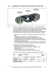
Expansion Module MAC00-FP2/FP4
4.7.2
MAC00-FP2 and FP4 Address and Termination setup
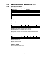
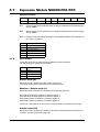
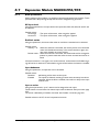
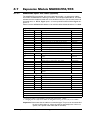
Each unit connected to the Profibus must be set up with a unique address.
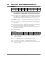
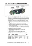
The illustration below shows how the address and termination can be set on the internal
dip switch. The dip switch is located on the internal circuit board.
MAC00-FP2 and FP4 Dip switch settings
Please notice that in newer modules
with firmware 3.01 or newer the address
Mini dip-switch
can only be set by software
OFF
Dip 1-7 - Address setting
(address range 0-127)
Dip 8 - Address set by software
Dip 9-10 - Line termination
Both set to ON =
Term. enabled
Both set to OFF =
Term. disabled
Rear side of the MAC00-FP2 or FP4
expansion module
ON
1
2
3
4
5
6
7
8
9
0
SW1
Notes.
SW1 default setting: All switches set to “ON”
except 9+10 which are “OFF” which corresponds to
- Address is set by software / - Termination disabled
“Address set by software” (DIP8) means that
the profibus address will automatically be set
to the same value as the motor address
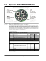
Dip switch location on the
MAC00-FP2 Expansion module
Cable glands
Basic MAC motor
housing
Internal circuit boards
Profibus and I/O
connectors.
Dip Switch placed
on the rear side of the
module
TT0946GB
Important: On newer modules with firmware 3.01 or 3.02 the dip switch 1 to 8 has
been disabled and the address can only be set in software by using for example MacTalk.
Please contact your JVL distributor if it is crucial to use the dip switch for address setup.
JVL Industri Elektronik A/S - User Manual - Integrated Servo Motors MAC050 - 3000
233