1
4.7
Expansion Module MAC00-FP2/FP4
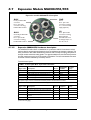
MAC00-FP4 connection description - continued.
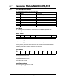
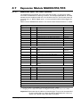
“BUS2” - Profibus-DP Interface. M12 - 5-pin female connector
Signal name
Description
Pin
no.
Cable: user
supplied
Isolation
group
5VDC
5V output. Can be used for ext. termination (Max 40mA)
1
-
2
A-
Terminal A (Siemens syntax) for the Profibus interface
2
-
2
DGND
Profibus-DP interface ground
3
-
2
B+
Terminal B (Siemens syntex) for the Profibus interface.
4
-
2
SHIELD
Cable shield. Internally connected to the motor housing.
5
-
2
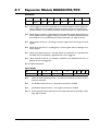
“IO” - I/Os and RS232 interface. M12 - 8-pin female connector.
Function
Pin
no.
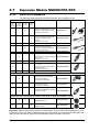
JVL Cable
WI1000-M12
M8T05N
Isolation
group
1
White
3
Signal name
Description
IOC
I/O terminal C.
Tx
RS232 interface - transmit output
Important !: DIP1 must be turned ON. If addressing is
used it must be turned ON at minimum one
of the connected motors.
2
Brown
1
Rx
RS232 interface - receive input
3
Green
1
GND
RS232 Ground - also used with analogue input
4
Yellow
1
5
Grey
3 (1 when
used as
AIN)
6
Pink
3
7
Blue
3
8
Red
3
DIP 5 = OFF : PL input
IOA
I/O terminal A.
DIP 5 = ON (default)
O1 (output PNP 25mA)
DIP 2 = ON(default) and
DIP 3 = OFF (default): AIN
(Analogue in or Zero search input)
DIP2 = OFF and DIP 3 = ON : O2
(output 2 / PNP 25mA)
DIP 4 = OFF (default): IN1 (input 1)
IOB
I/O terminal B.
IO-
I/O ground to be used with IN1, NL, PL, O1, O2
IOD
I/O terminal D.
DIP 4 = ON : O1 (PNP 25mA)
(output 1)
DIP 6 = OFF: NL
(negative limit input)
DIP 6 = ON(default): O+ (outp.sup.)
Cable Screen
Some standard cables with M12 connector offer a screen around the cable. This screen on some cables is
fitted to the outer metal at the M12 connector. When fitted to the MAC00-FP4 module, this means that the
screen will have contact with the complete motor housing and thereby also the power ground (main ground).
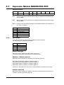
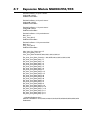
DIP-switch default setting
The Dip-switches are default set to the following positions:
DIP1 (TX-PD)=ON
DIP2 (AIN to IOA terminal) = ON
DIP3 (O2 to IOA terminal) = OFF
DIP4 (O1 to IOB) = OFF
DIP5 (O1 to IOC) = ON
DIP6 (O+ to IOD) = ON
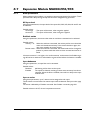
Isolation groups
The MAC00-FP4 offers optical isolation at the digital inputs and outputs (IN1, NL, PL and O1-2). The table
shows a number for each pin. This number refers to the isolation group to which the pin is connected.
Isolation group 1 means that the terminal refers to the main ground (P-, GND and the motor housing).
Isolation group 2 means that the terminal refers to the Profibus-DP interface ground (DGND).
Isolation group 3 means that the terminal refers to the I/O ground (IO-)
JVL Industri Elektronik A/S - User Manual - Integrated Servo Motors MAC050 - 3000
247