1
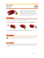
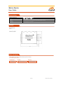
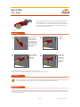
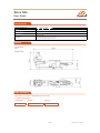
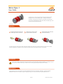
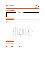
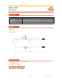
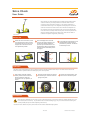
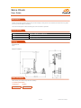
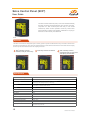
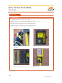
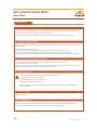
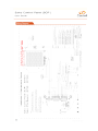
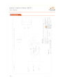
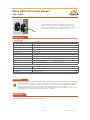
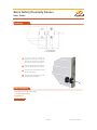
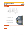
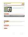
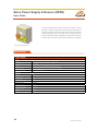
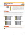
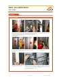
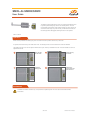
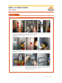
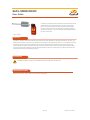
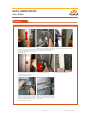
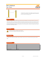
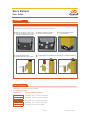
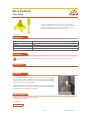
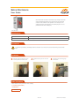
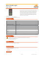
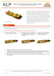
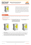
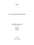
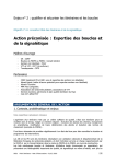
User Manual
www.castell.com
Contents
Section 1- Couplings
Salvo Susie. ..............................................................................................................................4
Salvo SGL (Glad Hand Lock) ...................................................................................................6
Salvo Type 1. ............................................................................................................................8
Salvo Club. .............................................................................................................................10
Salvo Chock. ..........................................................................................................................12
Section 2 - Powered Doors
Salvo SCP+ (Salvo Control Panel Plus). .................................................................................15
Salvo Safety Proximity Sensor (for Sectional Doors)..............................................................24
Salvo Safety Limit Switch (for Roller Shutter Doors). .............................................................26
Salvo Transformer. ..................................................................................................................28
Salvo Power Supply & Beacon (SPSB) . ................................................................................29
Section 3 - Manual Doors
SMDL-AIS-SMDB/SDMC (Manual Door Lock) ......................................................................32
SMDL-AI-SMDB/SDMC (Manual Door Lock) . .......................................................................35
SADL-SMDB/SDMC (Automatic Door Lock) ..........................................................................38
Section 4 - Loading Bay Barriers
Salvo Bollard. .........................................................................................................................42
Section 5 - Peripherals
Salvo Pedestal........................................................................................................................45
Salvo Enclosure. .....................................................................................................................46
................................................................................................................47
Section 6 - Safety Critical Information
Safety Critical Information. .....................................................................................................49
2
U-Salvo-2013-E Issue 1
Section 1
Couplings
U-Salvo-2013-E Issue 1
Salvo Susie
User Guide
Salvo Susie
Operation
The Salvo Susie lock is
ensures the vehicle air line is disconnected before
1
Disconnect the airline from the
trailer Susie air line connector.
2
Slide the Salvo Susie lock over the
exposed air line connector.
3
Rotate the key anti-clockwise
and remove the key.
Precautions
Maintenance
A lubrication point is provided at the opposite end of the key entry aperture. The recommended lubricant is Armna G4789 or
4 of 51
U-Salvo-2013-E Issue 1
Salvo Susie
User Guide
Technical Data
Working Temperature
Min -25ºC (ice free) Max. +55 ºC
Weight
Material
Stainless steel lock complete with TPE (Thermoplastic Elastomer) sleeve
Standards
Drawing
Dimensions:
in mm
SALVO SUSIE
Order Information
(** mandatory information)
Part Number**
005959
Symbol**
please advise
Dog Tag**
please advise
5 of 51
U-Salvo-2013-E Issue 1
Salvo SGL
User Guide
brake line connectors. Its purpose is to prevent re-connection of the air
only be removed with the permit key.
Salvo SGL
Operation
1
Disconnect the
airline from the
trailer connector,
then engage the
centre peg of the
SGL on to the air
line connector on
the trailer.
2
Rotate SGL
downwards.
3
Slide the SGL lock
portion towards
the air line
connector.
4
Only when the
Salvo SGL is on
the connecter
can the key be
rotated anticlockwise and
removed.
Removal of the SGL lock is the reverse of the above procedure.
Precautions
Maintenance
-
6 of 51
U-Salvo-2013-E Issue 1
Salvo SGL
User Guide
Technical Data
Working Temperature
Min -25ºC (ice free) Max. +55 ºC
Weight
Housing Material
Lock Material
Stainless Steel
Conforms with;
Standards
(USA) SAE J318 Glad Hand Connector
Drawing
Dimensions:
in mm
SALVO SGL
Order Information
(** mandatory information)
Part Number**
006504
Symbol**
please advise
Dog Tag**
please advise
7 of 51
U-Salvo-2013-E Issue 1
Salvo Type 1
User Guide
connectors. Its purpose is to prevent re-connection of the air brake
only be removed with the permit key.
Salvo Type 1
Operation
1
Disconnect the air line from the
Trailer Type1 air line connector.
2
Slide the Type1 lock over the
exposed air line connector.
3
Rotate the key anti-clockwise
and remove the key.
Precautions
Maintenance
8 of 51
U-Salvo-2013-E Issue 1
Salvo Type 1
User Guide
Technical Data
Working Temperature
Min -25ºC (ice free) Max. +55 ºC
Weight
Housing Material
Stainless steel
Lock Material
Stainless Steel
Standards
Conforms with; AS4945-2000
Drawing
Dimensions:
in mm
SALVO TYPE 1
Order Information
(** mandatory information)
Part Number**
006505
Symbol**
please advise
Dog Tag**
please advise
9 of 51
U-Salvo-2013-E Issue 1
Salvo Club
User Guide
Salvo Club
Operation
1
Begin by fully
closing the two
halves of the
Salvo Club. Then
place the Salvo
Club in position
over the steering
wheel.
2
Slide the two
halves of the
Salvo Club apart,
engaging the
hooks inside the
wheel.
3
Rotate and
remove the key.
4
The Salvo Club
is now locked in
place restricting
rotations of the
steering wheel.
Precautions
Maintenance
10 of 51
U-Salvo-2013-E Issue 1
Salvo Club
User Guide
Technical Data
Working Temperature
NA
Weight
Housing Material
Steel/Cro-moly Steel Construction with heat treated steel hook
Lock Material
Stainless Steel/Brass
Steering Wheel Size
Min. 22cm Internal Diameter; Max. 48cm Internal Diameter
Drawing
Dimensions:
in mm
SALVO CLUB
Order Information
(** mandatory information)
Part Number**
006476
Symbol**
please advise
11 of 51
U-Salvo-2013-E Issue 1
Salvo Chock
User Guide
side front wheel of the vehicle. Salvo Chock introduces discipline into
Salvo Chock
Before Use
1
When the chock is received, it will
The Lock Support Arm must be
raised to the vertical position and
2
the Chock ready for use, the Lock
Support Arm must be secured in
the operational position.
To complete the assembly the cover
3
provided in 6 positions. The Chock
is then ready for use.
prevent any movement of the arm.
The Retention Sleeve (B) should be
slid into position around the joint in
the spigot.
A
A
B
Operation
1
loosely around drivers-side front
wheel. Rotate the catch anticlockwise to the ‘up’ position, as
shown.
2
Press the pedal until the two chocks
contact the tyre. Continue until lock
springs into place.
3
Remove the untrapped key. The
chock is now secured in place.
Precautions
12 of 51
U-Salvo-2013-E Issue 1
Salvo Chock
User Guide
Maintenance
Technical Data
Material
Powder coated carbon steel and aluminium
Weight
Colour
Drawing
Dimensions:
in mm
Order Information
(** mandatory information)
Part Number**
007058
Symbol**
please advise
13 of 51
U-Salvo-2013-E Issue 1
Section 2
Powered Doors
U-Salvo-2013-E Issue 1
Salvo Control Panel (SCP+)
User Guide
The Salvo Control Panel Plus (SCP+) is the main interface between
+
comprises of a wall mounted panel with easy to use Castell
interlock key switch to allow operation of the bay. There is also
terminals on the internally mounted PCB.
SCP+
Operation
2
+
.
1
SCP+ with bay controls
isolated, ready to receive key.
2
Insert key and turn clockwise.
3
SCP+ with bay controls
energised, ready to open door
and deploy dock leveller.
Temperature (Operating)
Size
Mounting Hole
Material
Weight
Cable Entry Size
M20 x 2
Switch Approvals
IEC947-1.3 IEC947-5 BS EN60947 VDE 0660
UL Listed
TBA
Ingress Protection
IP55 Enclosure
Switch Rating
Power Supply Required
24VDC
Max Power Consumption
Power Frequency
15
U-Salvo-2013-E Issue 1
Salvo Control Panel (SCP+)
User Guide
Component Inputs
•
•
•
SPSB (Salvo Power Supply + Beacon)
SADL (Salvo Automatic Door Lock)
SBDS (Salvo Bay Door Sensor)
Component Outputs
•
•
•
•
Door Control
Dock Leveller Control
Amber Beacon
Precautions
Lockout/ Tagout:
+
Training:
Installation:
Always make connections to this device in accordance with instructions set forth in this manual and any
applicable electrical codes for your area.
Operation/ Maintenance:
WARNING
Never operate this unit with the access door open.
Never place any body parts near exposed electrical components.
Never force the electrical contacts or key solenoid to manually operate this unit.
Preinstallation Check
discrepancy.
the system.
16
U-Salvo-2013-E Issue 1
Salvo Control Panel (SCP+)
User Guide
Installation 1/4
Steps for installing the SCP+
Step 1: Specify location of SADL (inside / outside)
Step 2: Mount SCP+
Step 3: Install multi-core cable
Step 4(1):
Step 4(2): Install SPSB
Step 5(1): Install SADL
Step 5(2): Connect Door Close Limit Interface
Step 6: Connect Auto Door Control Interface
Step 7: Connect Dock Leveller Control Interface.
Step 8: Connect power (24VDC)
1 - Specify Location of SCP+
+
.
•
•
•
2 - Mount SCP+
+
3 - Install Multi-core Cable
An assessment of site conditions needs to be taken to determine the type of cable used. Armoured cable
where practicable.
17
U-Salvo-2013-E Issue 1
Salvo Control Panel (SCP+)
User Guide
Installation 2/4
4 (1)
4 (2) - Install SPSB
Mounting Holes:
Connections:
+
)
1: Connect to +V terminal of PSU
3: Connect to Earth terminal of PSU
+
)
5: Connect to + terminal of Beacon connector block
18
U-Salvo-2013-E Issue 1
Salvo Control Panel (SCP+)
User Guide
Installation 3/4
5(1) - Install SADL
Our standard 24V door locks are to be used (re SADL).
Connector 2: terminal 1 connect to terminal 2 of SADL (Door Lock)
Connector 2: terminal 2 connect to terminal 14 of SADL (Door Lock)
Connector 2: terminal 3 connect to terminal 4 of SADL (Door Lock)
Connector 8: terminal 4 connect to terminal 3 of SADL (Door Lock)
Connector 8: terminal 10 connect to terminal 1 of SADL (Door Lock)
4 (2) - Install SPSB
+
Typical SCP+ installation location outside warehouse.
hole as shown.
Typical SCP+
plate.
19
Typical SCP+ installation location outside warehouse
on pedestal.
U-Salvo-2013-E Issue 1
Salvo Control Panel (SCP+)
User Guide
Installation 4/4
5(2) - Connect Door Close Limit Interface
In the case of an automatic door there is not a requirement for the SADL however there is a requirement for
Connector 2 terminal 1 & 2: connected to bottom limit volt free contacts of the Door control panel.
6 - Auto Door Control Interface
the free position.
Connect to Connector 2 terminal 7 & 8:
The 7 & 8 terminals to be connected across the door inhibit terminal of the Door control panel.
Please note that the SCP+ is a failsafe device therefore if there is a failure then the door cannot be opened.
7 - Connect Dock Leveller Control Interface
It may be necessary to prevent activation of the dock leveler when the door is closed.
Connect to terminal 5 & 6 Connector 2.
8 - Power Supply Input
Connect 230/110VAC supply to SPSB (supply to be fused at 3A)
Connect Live to L (AC) terminal of PSU
Connect Neutral to N (AC) terminal of PSU
Connect Earth to Earth terminal of PSU
easily accessible.
The SCP+
20
U-Salvo-2013-E Issue 1
Salvo Control Panel (SCP+)
User Guide
Function
Condition
Door de-activated
Dock leveler de-activated
Vehicle restraint de-activated
SCP+
Door activated but not yet opened
Dock leveler de-activated
Vehicle restraint activated
SCP+
Door activated and opened
Dock leveler activated
Vehicle restraint activated
SCP+
Wiring
Connect ID
Description
24VDC
24VDC power connections Connector 1 Term 1 & 2
20w
Connect ID
Description
SADL/Door Closed
Solenoid controlled door lock or the door closed contact in the door control panel.
1.5mm²
1.5mm²
Connect ID
Description
Auto Door
N/O contacts to interlock with the door.
6A
1.5mm²
Dock Leveller
N/O contacts to interlock with the Dock leveller.
6A
1.5mm²
6A
1.5mm²
Beacon
N/O contacts to control beacon (24VDC).
6A
1.5mm²
6A
1.5mm²
Aux 1
21
U-Salvo-2013-E Issue 1
a
Salvo Control Panel (SCP+)
User Guide
Order Information
(** mandatory information)
Part Number**
007007
23
Symbol**
please advise
U-Salvo-2013-E Issue 1
Salvo Safety Proximity Sensor
User Guide
Salvo Safety Limit Switch
Proximity Switch
Normally Open
1500 VAC Max
3.0 A. Max
Carry Current
5.0 A. Max
3000 VDC Min
Contact Resistance
80 mOhms Max
15mm Min
-20°C / +85°C
-25°C / +90°C
Case Material
Brass (Nickel Plated)
Cable
Metal Threaded Magnet
Normally Open
-20°C / +85°C
-25°C / +85°C
Case Material
Brass (Nickel Plated)
Precautions
Maintenance
24 of 51
U-Salvo-2013-E Issue 1
Salvo Safety Proximity Sensor
User Guide
Installation
1
2
3
the door is fully closed.
4
Order Information
(** mandatory information)
Part Number**
007050
25 of 51
U-Salvo-2013-E Issue 1
Salvo Safety Limit Switch
User Guide
The Salvo Safety Limit Switch comprises a mechanical roller switch
and bracket set. It is mounted so that the roller is actuated by the
Salvo Safety Limit Switch
Product Type
Miniature Safety Limit Switch
Actuator
Side Rotary
Lever Style
Circuitry
1NC 1NO DPST Snap Action
10 A (Thermal)
240VAC / 250VDC
Plastic
Termination Type
M20
EN 50047
IP67 (EN60947-5-1
Approvals
Mechanical Life
15 Million Cycles
Precautions
Maintenance
26 of 51
U-Salvo-2013-E Issue 1
Salvo Safety Limit Switch
User Guide
Installation
Side Elevation
Plan View
1
be positioned approximately 3m above
2
mark the position of the holes.
3
4
Position the door bracket to ensure that
the switch roller is actuated when the
door is fully closed.
Order Information
(** mandatory information)
Part Number**
005606
27 of 51
U-Salvo-2013-E Issue 1
Salvo Transformer
User Guide
Salvo Transformer is used to convert power supplies of 415VAC down
to 230VAC. It is only required on sites where 230VAC is not available. It
is supplied as mounted in a polycarbonate enclosure
Salvo Transformer
Enclosure
Cable Entry
2 x M20 Glands
Transformer
63VA Transformer Input (0-230V - 400V) Output (2 x 0-115V)
Precautions
instructions.
Order Information
(** mandatory information)
Part Number**
007264
28 of 51
U-Salvo-2013-E Issue 1
Salvo Power Supply & Beacon (SPSB)
User Guide
The Salvo Power Supply converts 110/240V to 24VDC to power
Salvo Power Supply & Beacon
Specifications
Power Supply
Input
Current
Inrush Current
<2.0mA@240VAC input
Output
24V
Rated Load
0A
3.2A
Output Tolerance
+/- 1%
+/-0.5%
+/-0.5%
Ripple Noise MAX
120mV
85%
Power
29
U-Salvo-2013-E Issue 1
Salvo Power Supply & Beacon (SPSB)
User Guide
Specifications
Enclosure
Material
Dimensions
-25°C to +115°C
Shock Resistance
IP65
Beacon
Material
Dimensions
11/35VDC
Current
50mA
-20°C to +70°C
IP65
M20 x 2
Precautions
WARNING
accessible.
of this product.
force at the time of installation.
Order Information
(** mandatory information)
Part Number**
007008
30
U-Salvo-2013-E Issue 1
Section 3
Manual Doors
U-Salvo-2013-E Issue 1
SMDL-AIS-SMDB/SMDC
User Guide
The SMDL-AIS (Salvo Manual Door Lock) Is a mechanical interlock used
closes the switch contacts.
SMDL-AIS-SMDB
Operation
the switch contacts are open and the dock leveller is disabled.
operated as normal.
1
Insert the key
into the lock.
2
Rotate the key
clockwise.
3
Rotate the
locking bolt.
4
Release the
locking bolt and
open the door.
Precautions
instructions.
32 of 51
U-Salvo-2013-E Issue 1
SMDL-AIS-SMDB/SDMC
User Guide
Installation
4 (2) - Install SPSB
Step 01:
Step 02: Mark the position of the bolt Step 03: Drill the clearence hole in the
closed. Determine the position of the clearance hole on the inside of the door
bolt do not clash with bay controls.
Step 04: Determine the position of the
Step 05: Use the hole in the door Step 06: Mark and drill the positions of
Step 07:
place with the screws provided.
Step 08:
Step 09: Drill and pop-rivet two
positions. Check that the bolt rotates
rivet in place.
33 of 51
U-Salvo-2013-E Issue 1
SMDL-AIS-SMDB/SDMC
User Guide
Bolt Material
Stainless steel
Stainless Steel
Lock Material
Stainless Steel
10A
IP65
Termination
PG11
Approvals
Mechanical Life
Maintenance Instructions
with compressed air will prevent a build up of sediment in the locks.
etc.
of removal of released keys.
if appropriate.
that the systems are correctly installed and maintained in a satisfactory condition.
Order Information
(** mandatory information)
Part Number**
34
Description
Symbol**
006508
please advise
007044
please advise
006509
please advise
007045
please advise
Hand 1
Hand 2
U-Salvo-2013-E Issue 1
SMDL-AI-SMDB/SDMC
User Guide
The SMDL-AI (Salvo Manual Door Lock) is a mechanical interlock used
SMDL-AI-SMDB
Operation
operated as normal.
1
Insert the key
into the lock.
2
Rotate the key
clockwise.
3
Rotate the
locking bolt.
4
Release the
locking bolt and
open the door.
Precautions
instructions.
35 of 51
U-Salvo-2013-E Issue 1
SMDL-AI-SMDB/SDMC
User Guide
Installation
4 (2) - Install SPSB
Step 01:
Step 02: Mark the position of the bolt Step 03: Drill the clearence hole in the
closed. Determine the position of the clearance hole on the inside of the door
bolt do not clash with bay controls.
Step 04: Determine the position of the Step 05: Use the hole in the door Step 06: Mark and drill the positions of
Step 07:
place with the screws provided.
Step 08:
Step 09: Drill and pop-rivet two posi-
in place.
36 of 51
U-Salvo-2013-E Issue 1
SMDL-AI-SMDB/SDMC
User Guide
Bolt Material
Stainless steel
Stainless Steel
Lock Material
Stainless Steel
Maintenance Instructions
with compressed air will prevent a build up of sediment in the locks.
returned to Castell for repair if appropriate.
that the systems are correctly installed and maintained in a satisfactory condition.
Order Information
(** mandatory information)
Part Number**
37
Description
Symbol**
006510
please advise
007041
please advise
006511
please advise
007043
please advise
Hand 1
Hand 2
U-Salvo-2013-E Issue 1
SADL-SMDB/SDMC
User Guide
The SADL is a keyless solenoid controlled Lock that locks and unlocks
the door to be opened.
SMDL-AI-SMDB
Operation
+
unit.
. Once inserted and turned
+
+
Precautions
Wiring Instructions
38 of 51
U-Salvo-2013-E Issue 1
SADL-SMDB/SDMC
User Guide
Installation
Step 01:
Step 02: Mark the position of the bolt Step 03: Drill the clearence hole in the
closed. Determine the position of the clearance hole on the inside of the door
bolt do not clash with bay controls.
Step 04: Determine the position of the Step 05: Mark and drill the positions of Step 06:
place with the screws provided.
Step 07:
Step 08: Drill and pop-rivet two
positions. Check that the bolt rotates
rivet in place.
39 of 51
U-Salvo-2013-E Issue 1
SADL-SMDB/SDMC
User Guide
Bolt Material
Stainless steel
Zink alloy to BS EN 12844
Red Polyester Powder Coat
IP67
2500N
Max. Approach Speed
20M/min
Mechanical Life
Ambient Temperature
-5°C to 40°C (Mean over 24 hours = 35°C)
2
Connector Type
Switch Conformance
DIN VDE 0660 Part 206 & IEC
Positive Break
3A
230V AC max
2x2mm per Switch Element
Contact Material
24VAC/VDC
Maintenance Instructions
with compressed air will prevent a build up of sediment in the locks.
parts should be replaced or returned to Castell for repair if appropriate.
that the systems are correctly installed and maintained in a satisfactory condition.
Order Information
(** mandatory information)
Part Number**
Description
006479
007051
40
U-Salvo-2013-E Issue 1
Section 4
Loading Bay
Barriers
U-Salvo-2013-E Issue 1
Salvo Bollard
User Guide
of interlock (see table below). Each bollard is bolted to the warehouse
Salvo Bollard
Operation
+
unit.
-
+
Precautions
Maintenance
Post Material
Powder coated carbon steel
Cap Material
Dimensions
Colour
Safety yellow
Supplied
42 of 51
U-Salvo-2013-E Issue 1
Salvo Bollard
User Guide
Installation
3
2
1
drill with a suitable masonary drill.
4
Secure the Bollard to the
footplate with the bolts provided.
5
Lower the Bollard into place
over the footplate.
Fit appropriate kit to Bollards, test accordingly to complete installation.
Order Information
(** mandatory information)
Part Number**
Description/System Components
006513
006514
006515
006516
006517
43 of 51
U-Salvo-2013-E Issue 1
Section 5
Peripherals
U-Salvo-2013-E Issue 1
Salvo Pedestal
User Guide
primarily for installations that have a narrow bay pitch and limited wall
Salvo Pedestal
Post Material
Powder Coated Carbon Steel
1.46m
Colour
Safety Yellow
4 x M10 Rawl Bolts (supplied).
Precautions
Maintenance
Installation
trailer doors cannot strike the pedestal).
Additional steelwork (uni-strut) should be used to connect the pedestal to
+
cable can be tied
to the steel work for protection and support.
Order Information
(** mandatory information)
Part Number**
006480
45 of 51
U-Salvo-2013-E Issue 1
Salvo Enclosure
User Guide
and/or Palm/Glad Hand locks. The enclosure can be mounted at
Salvo Enclosure
Stainless Steel
Dimensions
200mm (w) x 300mm (h) x 131mm (d)
Precautions
Installation
3
2
1
bit.
into the holes.
Order Information
(** mandatory information)
Part Number**
006482
46 of 51
U-Salvo-2013-E Issue 1
Salvo Traffic Light
User Guide
closed and the vehicle can depart.
Dimensions
268mm (h) x 140mm (w) x 50mm (d)
Surface
IP400
-10°C - +50°C
40 x LED per circular array
24VDC
Life Expectancy
+7 years
89/336/EEC [CENELEC - EN
50082-1]
89/336/EEC [CENELEC - EN
50081]
73/23/EEC
2002/96/EC
Precautions
A seperate control system is required.
Wiring
Refer to SCP+
Order Information
(** mandatory information)
Part Number**
006538
47 of 51
U-Salvo-2013-E Issue 1
Section 6
Safety Critical
Information
U-Salvo-2013-E Issue 1
Safety Critical Information
User Guide
The system must be designed to meet the requirements of the Health and Safety Executive and all
current legislation. Attention is also drawn to the relevant codes of practice.
1. General Instructions
vibration washers should be used.
2. Spare Keys, Master Keys, Spare Access Locks Actuation Bolts/Tongues
•
•
Castell have an express order system for the rapid replacement of broken keys.
3. Verification
4. Training
49
U-Salvo-2013-E Issue 1
Safety Critical Information
User Guide
5. Safe Installation of Castell Electrical Products
electrical assembly are adequately earthed. This requirement is particularly critical in the case of key actuated locks
Castell offer an installation and maintenance service for its products and will be pleased to offer advice.
6. Maintenance of Castell Interlocks
WARNING
be replaced or returned to Castell for repair if appropriate. Users of interlock systems have a duty under section 2 of
in a satisfactory condition.
products.
EC-Declaration
50
U-Salvo-2013-E Issue 1
U-Salvo-2013-E Issue 1
Castell Safety International
The Castell Building
217 Kingsbury Road
London, NW9 9PQ
UK
Castell Safety International
Oskar-Jäger-Straße 137
50825 Köln
Germany
Castell Interlocks
150 N Michigan Avenue
Suite 800
Chicago IL 60601
USA
Castell Safety International
Building 1, No. 123
Lane 1165 Jindu Rd
Shanghai, 201108
China
t: +44 (0)20 8200 1200
f: +44 (0)20 8205 0055
t: +49 (0)221 169 47 94
f: +49 (0)221 169 47 95
t: +1 (312) 360 1516
f: +1 (312) 268 5174
t: +86 (0)21 6151 9028
f: +86 (0)21 6151 9030
[email protected]
www.castell.com
[email protected]
www.castell.com
[email protected]
www.castell.com
[email protected]
www.castell.com
ISO 9001
Q 10297