1
MPA-Light User Manual V1.2
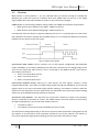
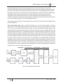
Strip Emulator Mode (OM = 01). In the Strip Emulator mode the output of the Analog FE is OR-ed
per column obtaining a vector of 16-bits which represents the hits per column and can be used as
Strip input by another MPA-Light in Stub finding mode. A 16:4 serializer transmits them at system
clock frequency (160 MHz nominal) through Strip[0:3]. Since the sample clock (40 MHz nominal) is
1/4 of the system clock, the 16 bits strip data are transmitted in one sample clock cycle starting from
the 4 LSB (bits 0 to 3). When the Strobe is high the data on the Strip pins are valid. The rising of this
signal coincide with the first transmission clock cycle of the system clock. The input strips for the
stub finding can be also generated from the test system. In this case the transmission must follow
some rules:
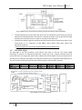
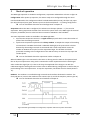
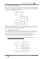
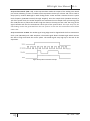
Strip transmission to MPA. The Strobe signal rising edge must be aligned with the first transmission
clock cycle (160 MHz) with valid Strip data. The Strobe signal allows the MPA-Light which receives
the data to align itself with the correct phase. The Strobe signal stays high up to the end of the
acquisition.
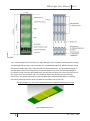
Figure 18 Strip data transmission example
25
PH – ESE – ME