1
MPA-Light User Manual V1.2
1
Introduction
The CMS tracker at HL-LHC is required to provide prompt information on particles with high
transverse momentum to the central Level 1 trigger. For this purpose, the innermost part of the
outer tracker is based on a combination of a pixelated sensor with a short strip sensor, the so-called
Pixel-Strip module (PS). The readout of these sensors is carried out by distinct ASICs, the Strip Sensor
ASIC (SSA), for the strip layer, and the Macro Pixel ASIC (MPA) for the pixel layer. The processing of
the data directly on the front-end module represents a design challenge due to the large data
volume (30720 pixels and 1920 strips per module) and the limited power budget. This is the reason
why several studies have been carried out to find the best compromise between ASICs performance
and power.
The higher luminosity for the Phase-II upgrade of LHC entails new challenges in the design of the
CMS silicon outer tracker. The higher granularity needed to keep the occupancy level at a few
percent and the requirement of having a good estimation of the z-coordinate of the hit gives rise to
the need of pixelated sensors. Furthermore, to keep the Level1 (L1) trigger rate at an acceptable
level (500 kHz to 1 MHz) requires the capability to perform quick recognition of particles with high
transverse momentum (pT). A particle traversing a set of two sensors spaced by about 2 millimetres
at an almost perpendicular direction to the plane of the sensors generates a, so called, "stub". The
stub is the elementary primitive to build a vector of these high momentum particles. The stub
finding is based on the concept that a low pT track bends more in the 3.8T magnetic field of CMS
than a high pT track, and it uses the distance between hits from the same track in these two sensors
to discriminate between them.
The requirements mentioned above together with the limited power and material budget drive the
development of the tracker modules: in order to generate stubs each module is composed by two
sensor layers, the first of which is a pixelated sensor to ensure the high granularity, while the other is
a strip sensor to limit the power consumed by the readout ASICs and to reduce the number of
electrical lines on the hybrid.
1.1
The Pixel Strip Module
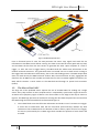
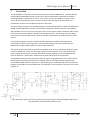
This new stub finding module accommodates a strip sensor and a pixelated sensor, covering an area
of approximately 5cm x 10cm, and is mounted on a mechanical assembly providing support and
cooling, as shown in figure 1. This module can be placed with different orientations in the outer CMS
tracker: in the barrel layers, the beam is parallel to the z-axis of the module, while in the end cap
layers, it is parallel to the y-axis of the module and in both configurations the x-axis stays on the r-phi
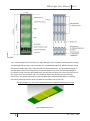
plane. Along the x-axis, the dimensions of the strips and pixels length is 100 um, while along the zaxis it is 2.5 cm for the strips and 1.446 mm for the pixels. Consequently, the strip sensor is
segmented into 2 x 960 strips while the pixel sensor is segmented into 32 x 960 pixels.
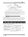
The strip sensor is read out from 16 Short Strip ASICs (SSA). Wire bonds provide the connectivity to a
high-density substrate carrying the ASICs that are bump-bonded onto it. The pixelated sensor
instead is read out by 16 Macro Pixel ASICs (MPA) distributed in two rows bump-bonded on it. Wire
bonds connect the MPA periphery to the same substrate carrying the SSA, hence realizing the topto-bottom connectivity.
3
PH – ESE – ME