1
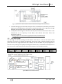
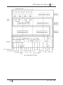
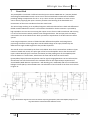
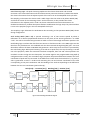
MPA-Light User Manual V1.2 4 Block Diagram The MPA-Light design has a Pixel Matrix and a Periphery. The ASIC block diagram is show in figure 7. Pixel Matrix includes 48 pixels distributed in 3 rows. Each pixel is composed of: • Analog Front End (FE) reads out the charge generated by an ionizing event in the pixel or by the test capacitance when the ASIC is not bump-bonded to a detector. The electronics is composed by a preamplifier, a shaper and a discriminator. The discriminator output is sent to the digital back-end which starts with the Pixel Logic. You can find details about Analog Front-End in Chapter 7 • Pixel Logic is common for a 2-pixels group and carries out the read-out of analog front-end. According to the configuration, it digitizes the discriminator output using ripple counter (asynchronous) or binary readout (synchronous). If enabled, the Pixel Clustering reduces the binary readout data before the transmission to the Periphery Logic. You can find details about the pixel logic in Chapter 8 Periphery includes three macro blocks: • Control Logic is responsible for the control of the ASIC. It generates the internal shutter, the clear signal and the Sample clock during acquisition (Shutter = ‘1’). These signals are distributed to the pixel matrix with one column every 8-pixels and to the periphery logic. The control logic receives the discriminator output signals from the FE and generates a trigger signal (OR-trigger). Also the serial interfaces are controlled by the Control Logic You can find details about the control logic in Chapter 6. • Periphery Logic processes and stores the data from the Pixel Logic. It receives the pixel logic output, processes them according to the configuration and stores the results upon the readout phase or sends them out through the Strip I/O. The storage is carried out with a dedicated collection of register called Periphery memory. It has a dedicate power supply (PVDD). You can find details about the periphery logic in Chapter 8. • Analog Bias generates the current and voltage references for the FE. It needs three external voltage references and includes also the Digital-to-Analog Converter (DAC) for Calibration pulse amplitude and Pixel Threshold. You can find details about Analog Bias in Paragraph 7.2 Configuration and readout are serial: • Serial Configuration allows loading the configuration registers in the Pixel Matrix and in the Periphery. You can find details about the Serial Configuration in Chapter 6. • Serial Readout allows the readout of the counters in the Pixel Logic and the Periphery memory. You can find details about the Serial Readout in Chapter 6. 9 PH – ESE – ME