1
MPA-Light User Manual V1.2
8
Modes of Acquisition
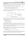
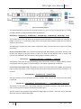
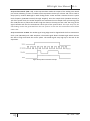
The acquisition phase is controlled by the Shutter. When it is open (Shutter = ‘1’) the Control Logic
generates the Clear pulse to clean the readout register, afterwards opens the IntShutter and
generates the SampleClk. The IntShutter starts the acquisition. The MPA-Light includes two
acquisition modes which are active during the acquisition: asynchronous and synchronous.
OR Trigger is an output control signal independent from the Shutter signal. It consists in the OR-ing
of the discriminator output of all the pixels. The output signal is sent directly as output (HitOR).
The acquisition modes digitize the Analog FE output within the pixel.
8.1
Pixel architecture
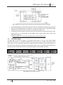
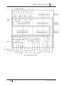
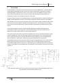
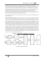
Every pixel includes Analog Front-End, 10-bits registers for pixel configuration and 2 AND gates to
filter the FE output before the acquisition system and a ripple counter for asynchronous acquisition.
The first AND gate filters the signal with the Pixel Mask (PM) bit of the configuration register, while
the second one with the IntShutter signal. If the signal passes the two AND gates, it gets to the
acquisition systems. The pixel clustering module includes the binary readout and the pixel clustering
logic. It is common for two pixels as the vertical buffers. The Vertical Buffer module buffers the data
from the pixel clustering module (Synchronous mode of acquisition), the data for the OR-Trigger
(before Shutter AND gate) and the bus from the pixels data from the rows above and transmits them
to the next pixel row, towards the periphery.
Figure 13 2-pixels architecture
21
PH – ESE – ME