1
S3C2500B
USB CONTROLLER
10.3 FUNCTION DESCRIPTIONS
10.3.1 USB BUS TOPOLOGY AND PHYSICAL CONNECTION
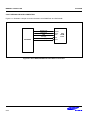
There are two kinds of cable connectors, A type for hub downstream port, and B type for device(or called as
function, Node). So end users easily connect cable.
USB cable physically contains 4 lines, 2 lines for signal D+/D-, 2 lines for power-supply to bus-powered device
such as mouse, keyboard. USB 1.1 spec compatibly manufactured cables could be used for USB 2.0 compliant
product. All cables in markets are not made to fit 1.1 spec correctly, but there is no problem for 1.1 or 1.0
compliant products except 2.0 products.
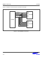
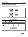
USB architecture uses bus tree topology. There is only one host controller in a root and the hub which lies right
next to host controller is called root hub. IBM-compatible PC with 2 USB ports means that there’re one host and a
root hub which has one upstream port from host controller and two downstream ports outside PC. South-bridge
chips in PCs, such as 82371AB/EB, contains USB host controller and root hub.
Compound devices can be designed; A monitor that has a CRT and a hub. Mouse or keyboard is attached to
downstream ports of this monitor-inside hub.
Maximum 5 hubs can lie between a host controller and a function because of signal delay.
10.3.2 FRAME GENERATION
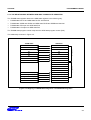
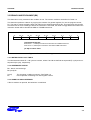
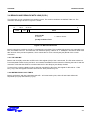
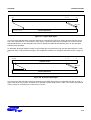
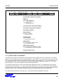
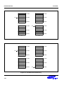
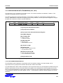
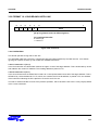
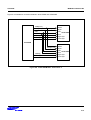
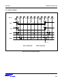
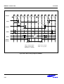
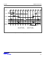
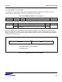
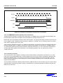
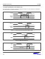
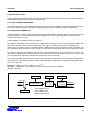
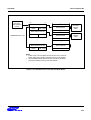
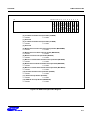
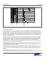
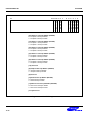
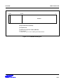
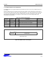
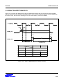
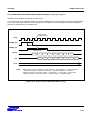
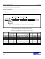
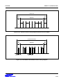
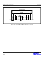
Frame divides time slot into 1ms units and the separators are SOFs (Start-of-Frames). Host broadcasts one SOF
packet at a normal rate of once every 1.00ms±0.0005ms. All ISO EPs in all devices can one IN/OUT per 1ms
time period. The SOF packet consists of SYNC, PID, frame number, CRC. The host transmits the lower 11 bits of
the current frame number in each SOF token transmission. When requested from the Host Controller, the current
frame number is the frame number in existence at the time the request was fulfilled. The current frame number
as returned by the host (Host Controller or HCD) is at least 32 bits, although the Host Controller itself is not
required to maintain more than 11 bits.
Frame N-1
SOF
EOF Interval (Frame N-1)
Frame N
SOF
EOF Interval (Frame N)
Frame N+1
SOF
SOF
EOF Interval (Frame N+1)
Figure 10-1. SOF Packets
All full-speed functions, including hubs, receive the SOF packets. Frame timing sensitive functions, which do not
need to keep track of frame number (e.g. a hub), need only decode the SOF PID; they can ignore the frame
number and its CRC. If a function needs to track frame number, it must comprehend both the PID and the time
stamp. Full-speed devices that have no particular need for bus-timing information may ignore the SOF packet.
The SOF token holds the highest priority access to the bus. Babble circuitry in hubs electrically isolates any
active transmitters during the End-of-Frame (EOF) interval, providing an idle bus for the SOF transmission.
10-3