1
UM10362
NXP Semiconductors
Chapter 23: LPC314x LCD interface
•
•
•
•
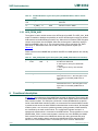
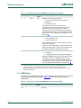
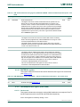
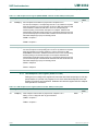
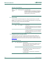
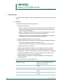
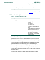
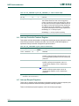
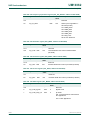
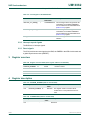
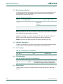
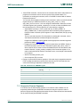
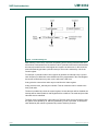
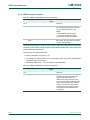
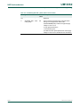
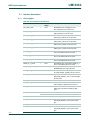
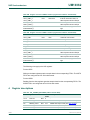
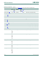
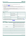
When the FIFO is empty (LCD_FIFO_EMPTY).
When the FIFO is half empty (LCD_FIFO_HALF_EMPTY).
When the FIFO is overrun (LCD_FIFO_OVERRUN).
When the requested instruction/data register is valid (LCD_READ_VALID).
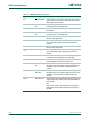
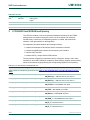
Any of these interrupts can be masked individually to keep them from generating an
interrupt to the CPU, by using the LCD_INT_MASK register. The interrupts after masking
can be read in the LCD_STATUS register. Writing a `1' in the mask register will mask the
interrupt. The status of the interrupts without masking can be read in the `LCD_INT_RAW'
register.
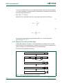
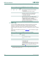
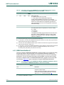
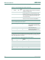
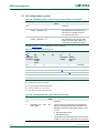
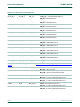
5.2 Clearing the interrupts
An interrupt can be cleared by writing a `1' to the respective bit in the LCD_INT_CLR
register. If the interrupt has not been solved, for instance the FIFO is still empty, this will
re-set the interrupt, when not masked.
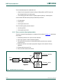
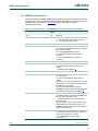
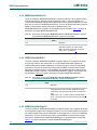
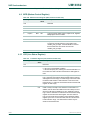
5.3 Using DMA flow control
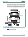
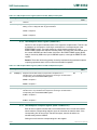
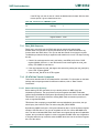
All data transfers towards the LCD interface can be done using the DMA and the
corresponding flow control, reducing CPU interrupting.
The DMA has the ability to transfer blocks of data from memory and the LCD FIFO while
checking the FIFOLEVEL flow control before sending data. This way data will only be
send when the LCD interface has space left in its local FIFO.
This construction allows much larger blocks of data to be transported to the LCD interface
than the maximal 16 bytes of the FIFO at a time.
If the external LCD controller supports it, a single enable command to the DMA controller
may refresh the complete LCD screen, making the LCD-controller a very low
CPU-intensive piece of hardware.
It requires a single DMA channel to transfer data to the LCD interface. If a linked-list must
be supported, then two sequential channels are required. See the DMA chapter of this
document for more info.
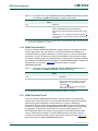
LCD-reading is not supported with DMA flow control.
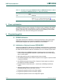
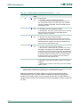
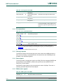
6. Power optimization
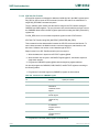
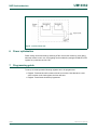
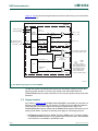
To reduce the power consumption, this module uses a gated clock. The clock coming from
the CGU will be disabled when the module is not in use.
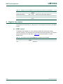
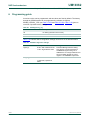
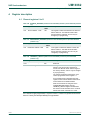
7. Programming guide
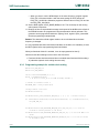
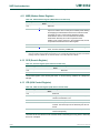
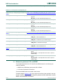
7.1 Resetting the external LCD controller
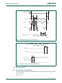
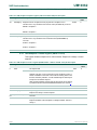
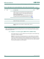
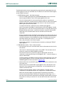
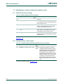
A GPIO pin or the system reset can be used to act as a reset signal for the external LCD
controller. In some cases a simple instruction to the controller is enough to perform the
reset.
UM10362
User manual
© NXP B.V. 2012. All rights reserved.
Rev. 1 — 7 December 2012
456 of 577