1
UM10362
NXP Semiconductors
Chapter 8: LPC314x High-speed USB On-The-Go (OTG) controller
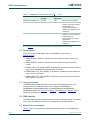
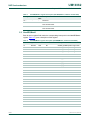
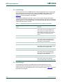
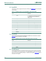
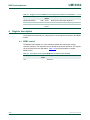
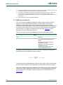
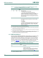
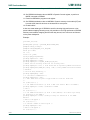
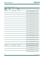
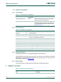
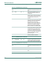
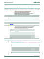
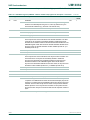
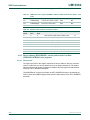
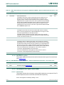
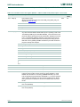
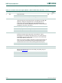
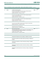
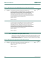
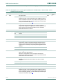
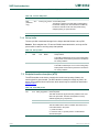
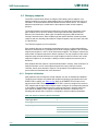
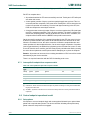
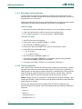
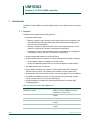
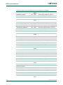
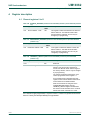
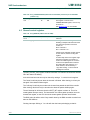
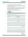
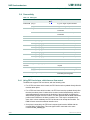
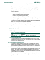
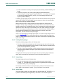
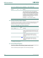
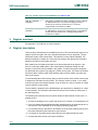
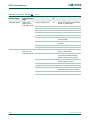
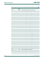
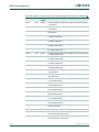
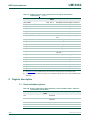
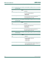
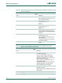
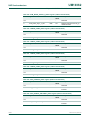
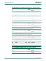
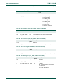
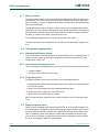
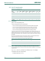
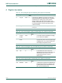
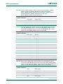
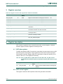
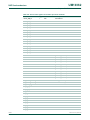
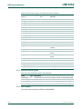
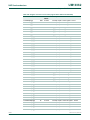
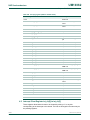
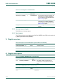
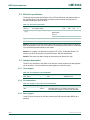
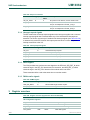
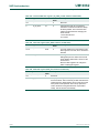
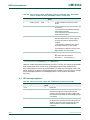
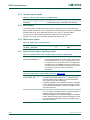
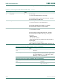
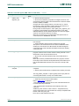
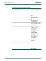
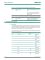
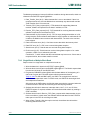
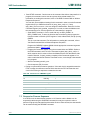
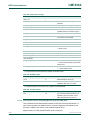
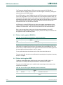
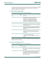
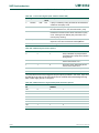
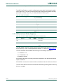
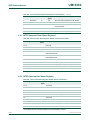
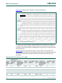
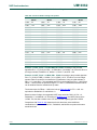
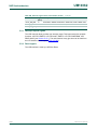
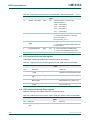
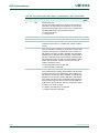
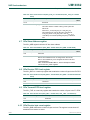
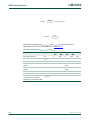
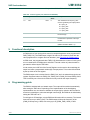
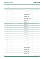
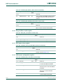
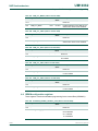
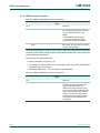
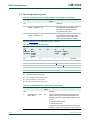
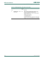
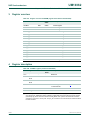
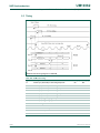
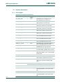
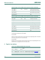
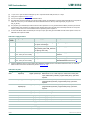
Table 107. USB Status register (USBSTS - address 0x1900 0144) register bit description - host mode …continued
Bit
Symbol Value
Description
Access
Reset
value
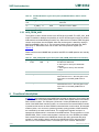
19
UPI
USB host periodic interrupt (USBHSTPERINT)
R/WC
0
31:20
1
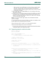
This bit is set by the Host Controller when the cause of an interrupt is a
completion of a USB transaction where the Transfer Descriptor (TD) has an
interrupt on complete (IOC) bit set and the TD was from the periodic
schedule. This bit is also set by the Host Controller when a short packet is
detected and the packet is on the periodic schedule. A short packet is
when the actual number of bytes received was less than the expected
number of bytes.
0
This bit is cleared by software writing a one to it.
-
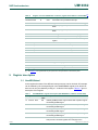
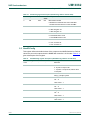
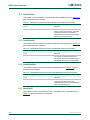
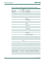
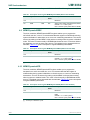
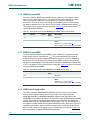
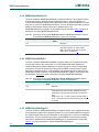
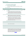
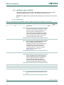
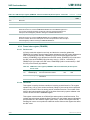
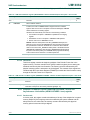
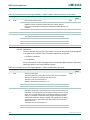
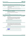
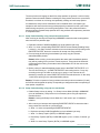
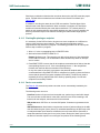
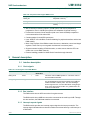
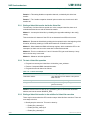
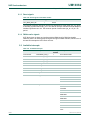
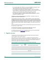
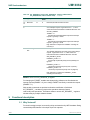
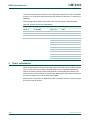
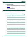
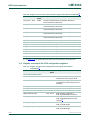
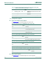
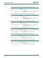
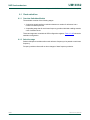
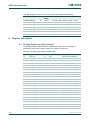
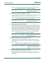
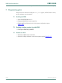
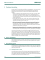
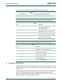
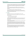
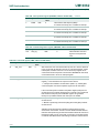
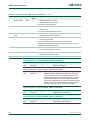
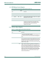
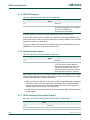
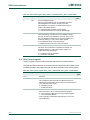
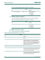
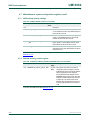
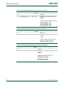
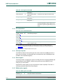
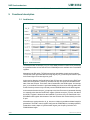
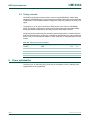
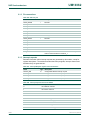
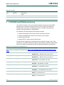
4.2.3 USB Interrupt register (USBINTR)
The software interrupts are enabled with this register. An interrupt is generated when a bit
is set and the corresponding interrupt is active. The USB Status register (USBSTS) still
shows interrupt sources even if they are disabled by the USBINTR register, allowing
polling of interrupt events by the software. All interrupts must be acknowledged by
software by clearing (that is writing a 1 to) the corresponding bit in the USBSTS register.
4.2.3.1
Device mode
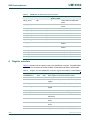
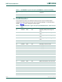
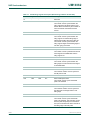
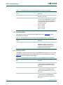
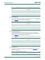
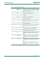
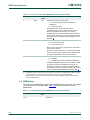
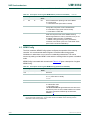
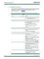
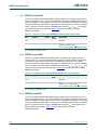
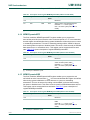
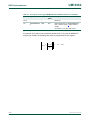
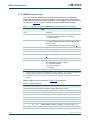
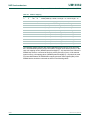
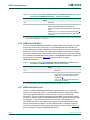
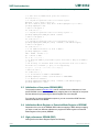
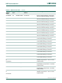
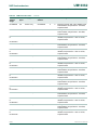
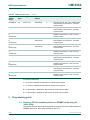
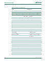
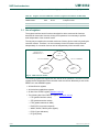
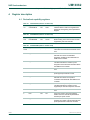
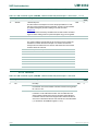
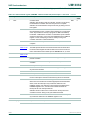
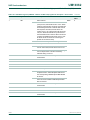
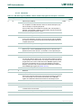
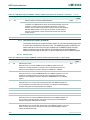
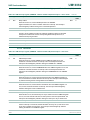
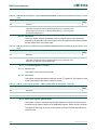
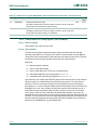
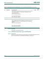
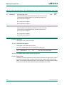
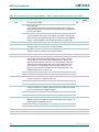
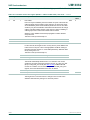
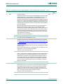
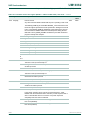
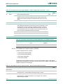
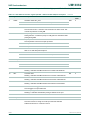
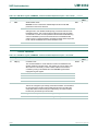
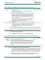
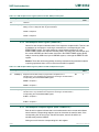
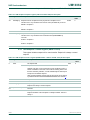
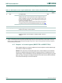
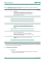
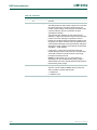
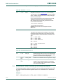
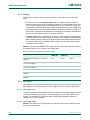
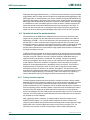
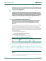
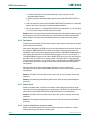
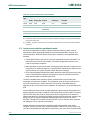
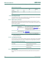
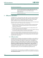
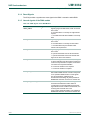
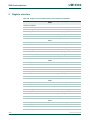
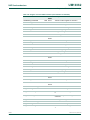
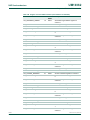
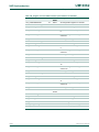
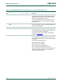
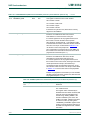
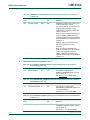
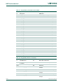
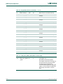
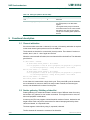
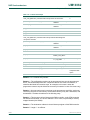
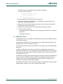
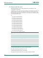
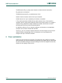
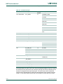
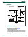
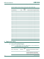
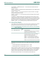
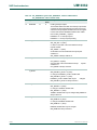
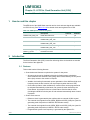
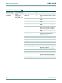
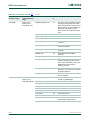
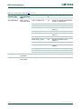
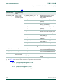
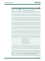
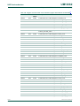
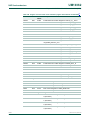
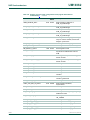
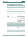
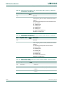
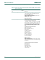
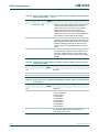
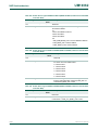
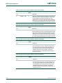
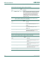
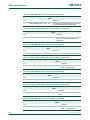
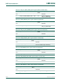
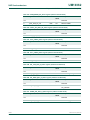
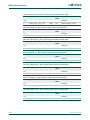
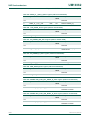
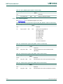
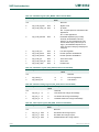
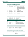
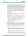
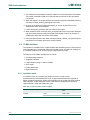
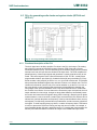
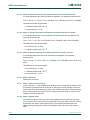
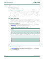
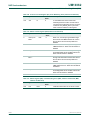
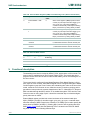
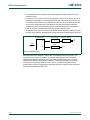
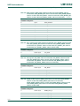
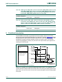
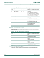
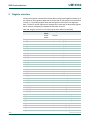
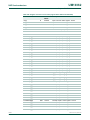
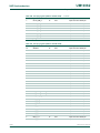
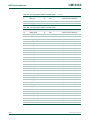
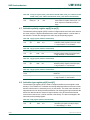
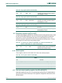
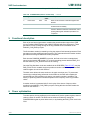
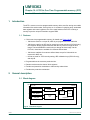
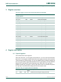
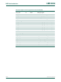
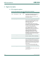
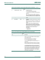
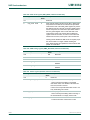
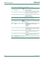
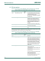
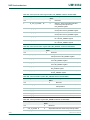
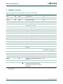
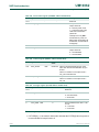
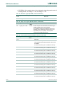
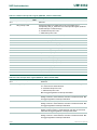
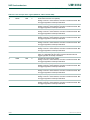
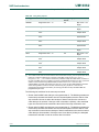
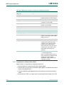
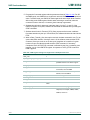
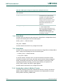
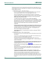
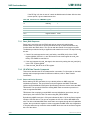
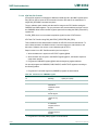
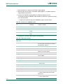
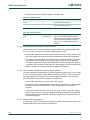
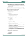
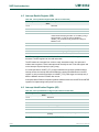
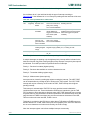
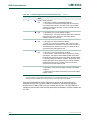
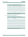
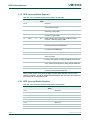
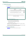
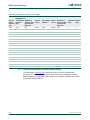
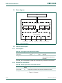
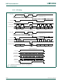
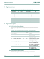
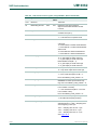
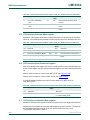
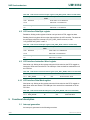
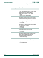
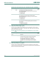
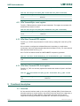
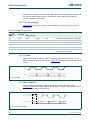
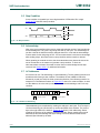
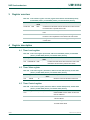
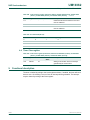
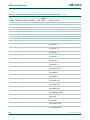
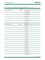
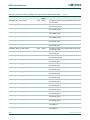
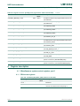
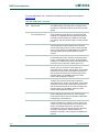
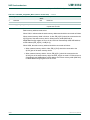
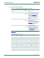
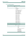
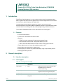
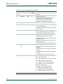
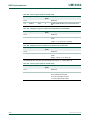
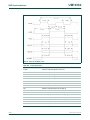
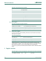
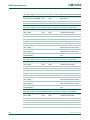
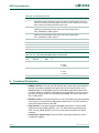
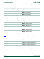
Table 108. USB Interrupt register (USBINTR - address 0x1900 0148) bit description - device mode
Bit
Symbol Description
Access Reset
value
0
UE
R/W
0
R/W
0
R/W
0
-
0
R/W
0
R/W
0
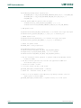
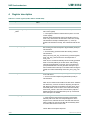
USB interrupt enable
When this bit is one, and the USBINT bit in the USBSTS register is one, the
host/device controller will issue an interrupt at the next interrupt threshold. The
interrupt is acknowledged by software clearing the USBINT bit in USBSTS.
1
UEE
USB error interrupt enable
When this bit is a one, and the USBERRINT bit in the USBSTS register is a one, the
host/device controller will issue an interrupt at the next interrupt threshold. The
interrupt is acknowledged by software clearing the USBERRINT bit in the USBSTS
register.
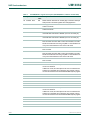
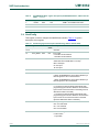
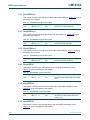
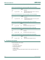
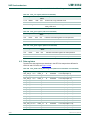
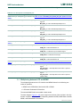
2
PCE
Port change detect enable
When this bit is a one, and the Port Change Detect bit in the USBSTS register is a
one, the host/device controller will issue an interrupt. The interrupt is acknowledged by
software clearing the Port Change Detect bit in USBSTS.
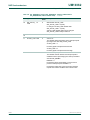
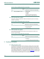
3
FRE
Not used by the Device controller.
4
-
Reserved
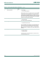
5
AAE
Not used by the Device controller.
6
URE
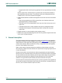
USB reset enable
When this bit is a one, and the USB Reset Received bit in the USBSTS register is a
one, the device controller will issue an interrupt. The interrupt is acknowledged by
software clearing the USB Reset Received bit.
7
SRE
SOF received enable
When this bit is a one, and the SOF Received bit in the USBSTS register is a one, the
device controller will issue an interrupt. The interrupt is acknowledged by software
clearing the SOF Received bit.
UM10362
User manual
© NXP B.V. 2012. All rights reserved.
Rev. 1 — 7 December 2012
124 of 577