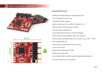
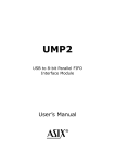
1
Washington University CSE 462 – Fall 2004 Semester Project Ultrasound Over USB Group 100 Arpith Jacob Brandon Harris Todd Bumgarner Ultrasound Over USB 10 December, 2004 Abstract The project implements two designs on the Xilinx SpartanII FPGA using an FTDI USB1.1 IC. The first design is a simple loopback that receives data from the host via the USB and retransmits it back to the host PC. The second design transmits selected scan data from an ultrasound backend to the PC host, supporting a maximum of 5 frames per second. To achieve acceptable frame rates on a USB1.1 bus, the amount of data transferred was cut down by a factor of four by selecting the sample closest to each pixel. VHDL was used to describe the hardware design, which was simulated with ModelSim and synthesized using the Xilinx tools. Linear interpolation was used to generate a 512 x 512 image from the scanned data. _____________________________________________________________________________________________ 12/10/2004 Page 2 Ultrasound Over USB I. Introduction The project implements an FPGA design to send Ultrasound Imaging data from a backend to the host PC via a USB1.1[1] link. A Xilinx SpartanII FPGA[2] was used to implement the hardware design, and the DLPUSB245M module [3] containing the FT245BM USB FIFO I.C.[4] was used to implement the USB1.1 protocol[1]. A conservative frame rate of 8 frames per second was targeted due to the bandwidth constraints (maximum 1 megabyte / second) imposed by the USB1.1 link, and the DLP D2XX driver[5]. In order to achieve this frame rate, sample selection was done in the hardware design to reject samples that did not contribute to the ultrasound image. The hardware design, done in VHDL, contains a sample selector module, a FIFO write controller module, and a USB interface module. The design communicates with the backend using eight 32bit registers that control the various parameters of the backend. These control registers can be read from or written to, from the host PC. Communication between the host PC software and the hardware is done using a special protocol over the USB. The transmission protocol allows bidirectional communication, and is designed to minimize the overhead on the host PC, thus maximizing the frame rate. _____________________________________________________________________________________________ 12/10/2004 Page 3 Ultrasound Over USB The host PC software is a Windows Command Line Application that communicates with the Ultrasound Probe using the D2XX drivers provided with the DLP module. It was designed to read and write from registers and read vectors forming an image frame. Checks are performed after receiving each vector, to determine their integrity and detect loss of synchronization. II. Architecture The architecture of the Ultrasound Probe is displayed in the included block diagram (Figure 1). It consists of four main modules: the backend, the sample selector, the FIFO write controller, data FIFO and control registers, and the USB interface module. The first three modules operate at a clock speed of 20MHz, while the USB interface module operates at a slower clock domain of 6MHz. Backend: The backend is a generic module that interfaces with the Ultrasound probe and sends sampled data to the sample selector. Over sampling by a factor of 4x is done at the backend, to produce a large number of samples, which can be used to produce an accurate image by linear interpolation[6]. Due to the bandwidth constraints of the USB link, sample processing must be done on the hardware to select the sample that best approximates each pixel, thus reducing the data to be transferred to the host PC by a factor of 4. The probe scans an image with a span of 90 _____________________________________________________________________________________________ 12/10/2004 Page 4 Ultrasound Over USB degrees, divided into 256 vectors in each scan. Vectors are numbered 0 – 255 in the forward scan and 256 – 511 in the reverse scan. Since each vector codes a maximum of 512 pixels, 2048 samples corresponding to each vector are sent by the backend. Provisions were also made to make the frame rate of the backend programmable. This is achieved by using the lower two bytes of Control Register 1 to set up a 16bit input to the backend that is used to adjust the dead time between vectors. Figure 2 shows the calculations used to program the frame rate. The column titled ‘offtime hex’ contains the value to be written to the control register for the desired frame rate. Sample Selector: The sample selector module determines the sample that best approximates each pixel on the vector. To facilitate this, it maintains an Initial Value, Delta and Length (see Figure 3: Initial Value Diagram) for each of the vectors in a Lookup Table. This information is stored for only 128 vectors due to the symmetric nature of the sweep. The Initial Value corresponds to the distance that must be traveled by the ultrasound wave after emission from the probe before it reaches the first pixel line. It is represented as a fixed point number in 2s compliment form. The Delta value represents the distance between two ultrasound samples. Since 2048 samples are generated by the backend for every vector in an image, they correspond to differing number of _____________________________________________________________________________________________ 12/10/2004 Page 5 Ultrasound Over USB samples or pixels along each vector (up to a maximum of 512 pixels). The length of each vector less 300 is also stored in the LUT. LUT value calculation: As displayed in Figure 3: Initial Value Diagram the Initial Value, Delta and Length vary as the angle subtended by each vector varies. As the ultrasound probe sweeps along the XY plane collecting samples, the angle subtended by each vector and the vertical Y axis varies as sinusoidal function between 0 to 45 degrees. The LUT values for each vector (corresponding to an angle) may be calculated as follows: Speed of sound in tissue (s): 1500 m/s Over sampling rate (o): 4x Probe radius (r): 0.376 * 0.0254 m Sampling frequency (f): 20 Mhz Distance between two samples at an imaginary vector at angle 0 degrees is: 2× d = t × s The time (t) traveled by sound is given by: 1 = 0.05 × 10 6 seconds f 0.05 × 10 −6 × 1500 ⇒d = 2 _____________________________________________________________________________________________ 12/10/2004 Page 6 Ultrasound Over USB At Angle Ө: Initial Value (Distance from probe to pixel line 0 along some vector at angle Ө), projected along the Yaxis: r IV (Θ) = − − r cos Θ metres cos Θ Delta (Distance between samples along some vector at angle Ө), projected along the Y axis: ∆(Θ) = d cos Θ metres Scaling IV and ∆ by ( 4 × d ) , the distance between two pixels: IV (Θ) = − ∆ (Θ) = r (1 − cos Θ ) 4d cos Θ 4 metres metres Number of samples along each vector: LEN (Θ) = 2048d cos Θ − r (1 − cos Θ ) 4d Expected frame rate: Theoretical bandwidth / Size of a single frame (total number of samples in the frame + header data) _____________________________________________________________________________________________ 12/10/2004 Page 7 Ultrasound Over USB = 1 × 10 6 = 9 fps 109218 + 4 × 256 For the required accuracy IV was represented as a 2s compliment fixed point value with a 16 bit whole number and 32 bit fraction. ∆ was represented as a 32 bit fraction and LEN as an 8 bit value. The precision required was confirmed by comparing the samples selected by the hardware to the expected results. The attached C program (Figure 4: lut.c) was used to generate the lookup table values (Figure 5: lut_out.txt) as .coe files (Figure 6) for use with the VHDL simulator and synthesizer tools. The sample selector is pipelined into four stages to provide sufficient time to transmit the USB header bytes for each vector before the first data sample arrives. Each stage also performs a function to help select a sample for each pixel. Address Translator: Stage 1 is an address mapping function that converts a vector number in the range 0 – 511 to an address for the lookup table in the range 0 – 127: VECTOR ADDRESS 0 – 127 => 0 – 127 128 – 255 => 127 – 0 256 – 383 => 0 – 127 384 – 511 => 127 – 0 _____________________________________________________________________________________________ 12/10/2004 Page 8 Ultrasound Over USB Lookup Table: The translated address (7 bits) is then used to address a LUT block, to determine the IV, Delta and Length for each vector. The LUT block consists of four block RAMs addressed by the vector number. Adder Block: This module maintains a running count of the distance traveled by each sample in an internal count register. At the start of each vector, the 48 bit fixed point count register is initialized by the IV value. For every sample received from the backend, the adder block adds ∆ to the count register. The count and ∆ values are passed to the next stage to determine the best sample for each pixel line. Good/Bad Block: This module determines the sample that best approximates each pixel line. Whenever a count value falls in the pixel window (1 ∆/2 and 1 + ∆/2) the corresponding data sample is transferred to the host. The following pseudo code summarizes this algorithm: IF (SIGNED(count(47 DOWNTO 32)) >= 0) THEN IF (UNSIGNED(count(31 DOWNTO 0)) >= (x"FFFFFFFF" UNSIGNED(2SCOMPLIMENT(delta / 2)))) THEN good0_bad1 <= '0'; ELSIF (UNSIGNED(count(31 DOWNTO 0)) < UNSIGNED(delta / 2)) THEN good0_bad1 <= '0'; _____________________________________________________________________________________________ 12/10/2004 Page 9 Ultrasound Over USB ELSE good0_bad1 <= '1'; END IF; ELSE IF (UNSIGNED(count(47 DOWNTO 32)) = 65535) THEN IF (UNSIGNED(count(31 DOWNTO 0)) >= UNSIGNED(2SCOMPLIMENT(delta / 2))) THEN good0_bad1 <= '0'; ELSE good0_bad1 <= '1'; END IF; END IF; FIFO Write Controller: The FIFO write controller is a 7 state machine that writes samples, as selected by the sample selector, into the Data FIFO (refer to the FIFO_WR_CNTRL section of Figure 7 for the state diagram of the FIFO Write Controller). At the start of each vector, the write controller detects a rising edge on the valid line from the backend and writes the four header bytes for the vector. The vector number and length fields of the header are passed on from the sample selector. The state machine monitors the good0_bad1 line from the sample selector and writes the corresponding data sample to the FIFO if it goes low. Since the value 00 is used in the header to indicate start of transmission, any data sample that equals 00 is incremented before writing. To avoid partial vectors being sent to the Host, a check must be added to drop an entire vector if the Data FIFO does not have at least 512 bytes of space. However, this was not implemented as it only serves to reduce the frame rate. This error condition can be handled in the software. _____________________________________________________________________________________________ 12/10/2004 Page 10 Ultrasound Over USB DATA FIFO and Control Registers: The 4KB Data FIFO is a dual port asynchronous FIFO that acts as a bridge between the two clock domains in the design. The FIFO Write Controller writes data into the FIFO on a 20MHz clock domain and the USB Interface Module reads data from the FIFO on a 6MHz clock domain. The size of the Data FIFO was selected to support the desired frame rates. Eight 32 bit Control Registers – addressed bytewise by the Host – are used to set various parameters at the backend. For example, the go bit (used to activate the backend) is the LSB of Control Register 0. USB Interface Module: The USB Interface Module controls reading and writing from the DLP Module using two state machines. The RxD machine (refer to the RXD_FSM section of Figure 7) receives Read and Write register commands from the host. A write command updates the internal register value that is used by the backend. Read register commands generate responses (4 bytes each) that are written to a Register FIFO. The RxD machine generates a response only if there are at least 4 bytes available in the Register FIFO. The TxD machine (refer to the TXD_FSM section of Figure 7) transmits either vector samples or register responses to the DLP module. Priority is given to vector samples read from the Data FIFO. Register responses are sent only if the Data FIFO is empty. In order to prevent the insertion of a register response frame inside a vector frame, transfer from the Register FIFO is _____________________________________________________________________________________________ 12/10/2004 Page 11 Ultrasound Over USB initiated in blocks of 4 bytes and only if the sample selector is not currently processing a vector (as indicated by the Valid signal). Since the RxD and TxD machines share the same data bus to the DLP module, a handshaking scheme is used to resolve bus conflicts (refer to the TXD/RXD Handshaking Note section of Figure 7). Priority is given to the RxD machine, so it may operate on the registers (set/reset the Go Bit). Additionally, a timeout feature is required to reset a state machine if no data transfer occurs after a predetermined time period. However, in the interest of simplicity, some of the advanced features were not implemented in the state machines. _____________________________________________________________________________________________ 12/10/2004 Page 12 Ultrasound Over USB III. USB Transmission Protocol Host PC to Hardware: 1. Write Register: 00 REG_VALUE 2. Read Register: 01 REG_NUMBER 3. Send Register Value: 00 02 REG_VALUE 4. Vector Data: 00 00/1 VECTOR REG_NUMBER Hardware to Host PC: REG_NUMBER LENGTH DATA Each field in the protocol is 8 bits wide. The reserved value 00 is used to denote the start of transmission and may not appear elsewhere in the data packet. Hence, all data values that correspond to 00 are incremented to 01. REG_NUMBER is a register to write to, and ranges in value from 0 – 31. REG_VALUE is an 8bit register value. The write register command is used to configure the USB probe, and to start the ultrasound scan by setting the LSB of register 0. VECTOR is a 9 bit vector number, with the MSB set in the LSB of the second byte of the header. The LENGTH field holds the number of samples selected for a vector. A constant value of 300 is subtracted from the length to get an 8bit resultant. The 8bit DATA field corresponds to the sample captured by the probe. There are 300 + LENGTH samples in each vector. Command Sequence: _____________________________________________________________________________________________ 12/10/2004 Page 13 Ultrasound Over USB REQUEST: HOST PC Write Register (1) Read Register (2) Set Go Bit (1) RESPONSE: USB PROBE No response Send Register Value (3) Send Vector Data (4) until Go bit is reset _____________________________________________________________________________________________ 12/10/2004 Page 14 Ultrasound Over USB IV. VHDL Implementation The hardware design outlined in the Architecture Section was implemented using RTLbased VHDL synthesized and targeted for the Spartan II device. A full listing of the VHDL source code is included in Figure 8. The usb_probe.vhd listing represents the toplevel module. Where used, all finite state machines were implemented using the three process model [7]. All VHDL was written by the authors using a hierarchical RTL design approach with the exception of the following modules which were created using the Xilinx CORE Gen tool: • lut.vhd o Lookup tables used for storing the initial values, delta values and lengths for each vector in the sample selector. Values are initialized via the input of an initialization file in the CORE Gen tool. A .mif file is output from the CORE Gen tool that allows for the use of the initialized memory during simulation. o Xilinx CORE Gen Module: SinglePort Block Memory v5.0 [8] • compl.vhd o Twos complementor used in the good_bad_block module. o Xilinx CORE Gen Module: Twos Complementer v6.0 [9] • data_fifo.vhd _____________________________________________________________________________________________ 12/10/2004 Page 15 Ultrasound Over USB o Asynchronous FIFO used to pass data from the sample selector to the bus interface module. This FIFO sits on the clock domain boundary between the backend/sample selector and the bus interface module. o This FIFO was sized to be 4k bytes in size. This size was chosen somewhat based on the available resources (it was made nearly as large as possible) and partially based on the following: Backend runs at 20MHz Bus I/F Module runs at 6MHz Target frame rate is 8 frames per second FT245BM USB FIFO IC maximum transmit rate (D2XX drivers) = 1MB/sec (8 Frames/sec) * (256 vectors/frame) * (512 bytesmax / vector) = 1.048MB/sec written into FIFO. Having a 4k Byte FIFO allows the backend to write data into the FIFO faster than the Bus I/F module can transmit it out (which is necessary if the Bus I/F module doesn’t actually achieve the 1MB/sec rate). o Xilinx CORE Gen Module: Asynchronous FIFO v5.0 [10] • synch_ctrl_reg_fifo.vhd _____________________________________________________________________________________________ 12/10/2004 Page 16 Ultrasound Over USB o Synchronous FIFO used in the bus interface module to buffer up control register data to be sent to the host. o This FIFO was sized to be 128 bytes deep. This size was chosen such that the design could handle a request for up to all 8 of the 32 bit control registers at any time. o Xilinx CORE Gen Module: Synchronous FIFO [11] The VHDL was compiled and simulated using ModelSim. VHDL testbenches were created to test the implementation and are included in Figure 9. All VHDL was synthesized using Synopsys’ FPGA Compiler II. The synthesis results are presented in Figure 10. Using the Xilinx ISE toolset, the synthesized code was mapped to the Spartan II device (device xc2s200, package pq208, speed 5) and place and route (PAR) was run. Both clock domains were constrained to run at 30MHz. The PAR results are summarized in Figure 11. As shown in the figure, all timing requirements were met and all mapped logic was successfully placed within the target’s available resources. _____________________________________________________________________________________________ 12/10/2004 Page 17 Ultrasound Over USB V. Software The software was developed around the D2XX driver provided by FTDI. The D2XX driver has simple function calls to Open, Read and Write as well as more complex functions to control parameters like Latency and Timeouts (refer to Figure 12: D2XX API Summary). Two forms of software were developed, a command line interface with several options and debugging capabilities and a less flexible GUI which provided no options but performed scan conversion and draws the image to the screen. Although very different in function, both programs have several similar underlying methods. The most import is the “Warm up” process. There exists an error in the current version of the D2XX driver which causes the first byte written after the driver is loaded to be lost. Since the hardware is designed to only handle complete messages, this data loss poses a significant problem. To avoid this software implements a warm up process which writes [1,1] to the device. Under normal circumstances, this is a “Read Register 1” command. If a complete Read Register 1 command is received by the hardware, it will respond with [0,2, 0,1]. If the command is not completely received, the hardware will not respond and the next software Read command will timeout. In the case of a read timeout, the software assumes the first byte was lost and transmits [1]. Thus the hardware will always receive a properly formatted “Read Register 1” command, regardless of whether the first byte was lost. _____________________________________________________________________________________________ 12/10/2004 Page 18 Ultrasound Over USB Command Line – The Command Line Program (CLP) represents the main tool for system verification and debugging (refer to Figure 13 for a listing of the C Code). While it is capable of reading and writing single bytes, its utility is in its ability to perform several higher level operations. Reading and writing registers is one such operation. This can be used to manually set the frame rate or GO bit. The CLP is also capable of taking in a desired frame rate, converting it to a timer value and writing it to registers 4 and 5 (which correlate to the lower two bytes of Control Register 1). The most useful options are Vector and Benchmark. Vector reads 512 vectors and stores them in a 512 by 512 array which can then be written to file. Benchmark takes in a starting frame rate and a step size, and attempts to calculate the maximum frame rate for the system. It does so by repeatedly reading many images and increasing the frame rate by the step size until the images can no longer be read successfully. Scan Conversion GUI – Scan conversion of the samples received from hardware is done by linear interpolation. Using sample values on a pixel line at adjacent vectors, values for every pixel between the two vectors can be calculated using the following formula (see Figure 14 for a graphical representation): A × c + B × (1 − c ) _____________________________________________________________________________________________ 12/10/2004 Page 19 Ultrasound Over USB A program to perform scan conversion is attached to this report (refer to Figure 15 for the source code for scan.c). A GUI program was written in Windows to receive sample data from the hardware and scan convert it to produce a grayscale image (see Figure 16: scan_img). The program consists of two threads: Display and Communication. The Communication thread performs entire reads of frames from the Ultrasound Probe, using the D2XX Driver API. Samples in each frame are passed to the Display thread which performs scan conversion using a precalculated table of coefficients. Pixel values are then plotted in a window to produce a 512 x 512 image. In practice however, the program could not keep up with the arrival of data from the hardware and quickly lost vectors after the first frame. We believe this is due to the inefficient pixel by pixel plotting function used to produce the image. More advanced libraries must be used to speed up the drawing of an image in order to keep up with the data being received over the USB link. _____________________________________________________________________________________________ 12/10/2004 Page 20 Ultrasound Over USB VI. Timing Analysis and Results Extensive timing analysis was performed on the VHDL implementation via simulations using Modelsim. Figure 17 depicts the results of one such simulation run. The simulation run depicted in the wave windows captured in Figure 17 depicts the following actions (as documented in tb_bw_test.vhd in Figure 9): • Host sending down frame rate control settings (2 frames per second) • Host reading back the frame rate control setting • Host sending down the GO bit • Backend transmitting vector data out to the Host at 2 frames per second • Host sending down Stop bit • Host sending down different frame rate (6 frames per second) • Host sending down the GO bit • Backend transmitting vector data out to the Host (6 frames per second) Using the adjustable frame rate feature of the backend, the design was tested on actual hardware to determine the actual frame rate achieved. Using the CLP on a 2.4 GHz Xeon Workstation the design was able to reliably support frame rates up to 4.625 fps. Using a 3.06 GHz P4 Laptop, the design was able to reliably support a frame rate to 5.125 fps. When the frame rate was increased to 5.25 frames per second, the data stream became corrupt after running for several seconds. _____________________________________________________________________________________________ 12/10/2004 Page 21 Ultrasound Over USB When the frame rate was increased to 5.5 frames per second, the data stream became corrupt almost immediately. _____________________________________________________________________________________________ 12/10/2004 Page 22 Ultrasound Over USB VII. Conclusions Although the design was only demonstrated to work reliably at 5.125 frames per second in comparison to the 8 frames per second targeted and 9 frames per second calculated, it is felt that further optimizations in the software hardware could be made to increase the frame rate beyond what has been demonstrated. If more time permitted, the group would have further investigated bulk data transfers on the PC end and also gotten more creative with toggling the send immediate discrete on the DLP module after each vector had been written to the DLP’s FIFO. Both of these concepts have the potential to increase the ability to reach the targeted frame rate (details on both are, coincidentally, not adequately described in the documentation published by FDTI). In addition to the aforementioned, the following enhancements would also be considered in future versions which add robustness and functionality of the Ultrasound Over USB design: • Add a FIFO almost full check to the FIFO_WR_CNTRL finite state machine to ensure that there is sufficient space in the FIFO for the next vector’s data prior to beginning to write it in the data. This would help to avoid some synchronization issues with the software which could result if the FIFO got full and only part of a vector was sent. • Insert the ability to handle control register read requests while transmitting vector data. Insert ability to handle Control Register read requests while transmitting vector data. The _____________________________________________________________________________________________ 12/10/2004 Page 23 Ultrasound Over USB Bus Interface Module could read in the length of the vector and once it has sent that many bytes, it could service one or more reads from the Control Register readout FIFO. Additional analysis would be required to determine exactly how many reads could be service in between vectors due to the fact that if no limit is placed on how many are serviced, the frame rate could be negatively impacted. Coincident with the hardware change, the application software would have to be updated to be able to digest the interleaving of vector data and control register data. • Consider moving to a smaller FPGA. As shown in Figure 11, the current firmware design is only occupying 32% of the Spartan II X2C200 part. It would be worth while at this stage of the design to look at other available (smaller and cheaper) FPGAs. The current design is currently using 92% of the 7kB Block RAM available on the chip. This would also factor into any new device selected; however, many of the newer devices (Xilinx Spartan 3, for example) are coming with more Block RAM resources. For the low cost of nonrecurring engineering expense it would take to port the design to a new FPGA, the recurring savings could pay off fairly quickly. • Consider a USB 2.0 solution. The weakest link in the design right now for increasing frame rate is the USB 1.1 interface. By moving to USB 2.0, the frame rate could be significantly increased. Several solutions are available on the market now (albeit, _____________________________________________________________________________________________ 12/10/2004 Page 24 Ultrasound Over USB slightly more complex in nature) such as the QuickUSB QUSB2[12] module from BitWise Systems which is based on the Cypress CY7C68013128AC EZUSB FX2 microcontroller. _____________________________________________________________________________________________ 12/10/2004 Page 25 Ultrasound Over USB VIII. References [1] “Universal Serial Bus Specification Revision 2.0,” April 27, 2000. [2] “SpartanII 2.5V FPGA Family: Complete Data Sheet,” 2004. [3] “DLPUSB245M User Manual,” Datasheet [4] “FT245BM USB FIFO (USB – Parallel) I.C., Version 1.4” Datasheet [5] “FTD2XX Programmer’s Guide Version 2.01” [6] William D. Richard, R. Martin Arthur, “Realtime Ultrasonic Scan Conversion via Linear Interpolation of Oversampled Vectors,” in Ultrasonic Imaging 16, 1994. pp. 109 – 123. [7] William D. Richard, “Everything You Always Wanted to Know About Synthesizable VHDL But Were Afraid to Ask”, 2003. [8] “SinglePort Block Memory v5.0 Product Specification” Xilinx, 2002. [9] “Twos Complementer v6.0 Product Specification” Xilinx, 2002. [10] “Asynchronous FIFO v5.0 Product Specification” Xilinx, 2002. [11] “Synchronous FIFO v3.0 Product Specification” Xilinx, 2001. [12] “QuickUSB QUSB2 Datasheet” BitWise, 2002. _____________________________________________________________________________________________ 12/10/2004 Page 26