1
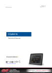
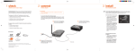
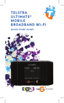
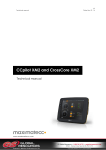
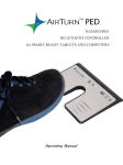
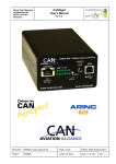
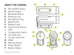
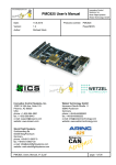
USER MANUAL AND REFERENCE HANDBOOK CrossLink BTC User manual and reference handbook www.maximatecc.com Revision: B.10 141002 Date: Oct 2, 14 CrossLink BTC User manual and reference handbook Revision: B.10 141002 Date: Oct 2, 14 Contents 1. Introduction ............................................................................................................................. 3 1.1. Functions and Features ............................................................................................................ 3 1.2. Technical data........................................................................................................................... 4 1.3. References .................................................................................................................................. 4 1.4. Dimensions .................................................................................................................................. 5 1.5. Identification .............................................................................................................................. 6 1.6. Environmental Tolerance ......................................................................................................... 6 1.7. Installation ................................................................................................................................... 6 2. Electrical Interface.................................................................................................................. 7 2.1. Connectors ................................................................................................................................. 7 2.2. Electrical Interface Overview ................................................................................................. 8 2.3. Electrical Interface Characteristics ........................................................................................ 9 2.4. Power Interface ....................................................................................................................... 11 2.5. LED Indicators ........................................................................................................................... 11 3. Appendix 1 – Environmental Tolerances ............................................................................. 12 4. Technical Support ................................................................................................................. 13 5. Trade Mark, etc. .................................................................................................................... 13 Index........................................................................................................................................... 14 www.maximatecc.com CrossLink BTC User manual and reference handbook Revision: B.10 141002 Date: Oct 2, 14 1. Introduction CrossLink BTC is a compact and ruggedized communication module designed for mobile applications. The unit has a wide power supply range, a wide operating temperature range and is EMC certified. Silicon moulding ensures high resistance to moisture, vibration and shock loads. With a pair of CrossLink BTC modules you can create a wireless CAN bridge via a Bluetooth Network. This means that you can connect CAN networks on different vehicles, machines and devices. The CAN bridge is completely transparent to the network. Because of this, any CAN protocol may be used, including DeviceNet, CANopen, SDS, CANaerospace, J1939 and CAN Kingdom. CrossLink BTC can also be paired with a CrossCode BT unit. This arrangement is intended for applications with a handheld, or stationary, remote unit where the CrossCode BT unit handles HMI-related I/O such as joysticks, switches, push buttons etc. This manual describes how the CrossLink BTC should be used. 1.1. Functions and Features CrossLink BTC is a gateway module between 2 CAN networks. The following types of networks can be linked together: CAN Interface - ISO 11898-2 (High Speed CAN) Supports all CAN protocols, including: CANopen, DeviceNet, SDS, CANaerospace, J1939 and CAN Kingdom. Bluetooth® Class 1 Interface - 100 m range www.maximatecc.com 3 CrossLink BTC User manual and reference handbook Revision: B.10 141002 Date: Oct 2, 14 1.2. Technical data Processor Fujitsu MB90F342CAS PFV-G SE1 Physical Housing Dimensions Plastic enclosure filled with silicon compound. With base plate L x W x H: 133 x 88 x 30 (46.including connectors) Environment Operating Temperature Range Protection rating EMC Conformity -40 ˚C to +75 ˚C IP67 (IEC 60529) ISO 14982 for Emissions, ISO 11452-2 for Immunity Power Supply Operating voltage 9 to 32 VDC Indicators One red/green LED indicator for CAN interface One blue LED indicator for Bluetooth© CAN interface Baud Rate ISO 11898-2 (High Speed CAN) 20 kbit/s to 1 Mbit/s set with rotary selector switch 0-7 Bluetooth® Interface Range Baud Rate Wireless serial interface via Bluetooth®, Class 1 100 meters 1 Mbit/s Connectors SERIAL: DIN M12 FCC ID and IC ID: QOQWT11I I C: 5123A-BGTWT11I Modular approach has been used in accessing the USA and Canada markets. CAN: DIN M12 Power: DIN M12 Certifications / Compliance 1.3. References Bluetooth: http://www.bluetooth.com/ CE Marking: http://ec.europa.eu/ International Standards Organisation: http://www.iso.org/ International Electrotechnical Commission: http://www.iec.ch/ www.maximatecc.com 4 CrossLink BTC User manual and reference handbook Revision: B.10 141002 Date: Oct 2, 14 1.4. Dimensions 88 34 The CrossLink BTC dimensions and placement of the four mounting holes are illustrated below. All dimensions are in millimetres. 46 133 114 www.maximatecc.com 5 CrossLink BTC User manual and reference handbook Revision: B.10 141002 Date: Oct 2, 14 1.5. Identification There is a label on the front of CrossLink BTC. On the label there are numbers which identify your unique module. Take note of them. During service and other contact with the supplier it is important to be able to provide these numbers. 1.6. Environmental Tolerance CrossLink BTC has been designed to cope with tough environmental demands. Strict tests have been conducted on the unit in order to ensure that it fulfils the expectations of a rugged unit. Much work has been performed to choose and design integral components so that they, in the best possible way and under all circumstances, provide you with a dependable working instrument. In Appendix 1, a list of standards can be found according to which CrossLink BTC has been tested and approved. Despite thorough design requirements and testing specifications, it is always best to install and handle CrossLink BTC with care. For more information, read further. 1.7. Installation CrossLink BTC should be installed in such a way that the module is not exposed to any unnecessary stress, heat, vibration or moisture. In this section, some recommendations are made regarding methods for how the unit should be installed. Minimum safety distance between human and the Bluetooth antenna is 20cm. If the unit is opened by non-authorised personnel, the warranty becomes void. 1.7.1. Cooling Although CrossLink BTC can operate in relatively high temperatures, cooling should still be considered when installing. If the unit becomes too warm, it may not perform to its full capacity and, with high temperature, cease to function. Inadequate cooling may lead to overheating, causing permanent damage to the unit. 1.7.2. Vibration We recommend installing CrossLink BTC in such a way that it is not unnecessarily exposed to vibration or other stress. 1.7.3. Rain / Moisture CrossLink BTC shall preferably be covered or enclosed in order to prevent direct exposure to water. www.maximatecc.com 6 CrossLink BTC User manual and reference handbook Revision: B.10 141002 Date: Oct 2, 14 2. Electrical Interface 2.1. Connectors Notice that the connector descriptions are those which are located on the unit, not those that the attached cables shall have in order to mate with them. Use caution when plugging/unplugging connectors. If the pins become bent or damaged they may not function correctly, or in the worst case, CrossLink BTC or other equipment may be damaged. Pwer Supply Connector X1 Pin X1.1 Default Signal +24 Vbatt Comments Main Power Input X1.2 +24 Vbatt Main Power Input X1.3 X1.4 GND Main Ground Input GND Main Ground Input DIN M12 x 1 male, 4-pole, A-coded 2 3 1 4 SERIAL Connector X2 Pin X2.1 Default Signal GND X2.2 RXD X2.3 TXD X2.4 RTS X2.5 CTS Comments DIN M12 x 1 female, 5-pole, A-coded CAN 1 Connector X3 Pin Default Signal X3.1 CAN Sheild X3.2 V+ X3.3 GND X3.4 CANH X3.5 CANL Comments DIN M12 x 1 male, 5-pole, B-coded 2 3 5 1 4 SMA Antenna Connector This connector is used to attach an external Bluetooth antenna. Only antennas certified to use with Bluegiga circuit (WT11) should be used. If an extension cable shall be used between the unit and the antenna, choose a cable suited for 2,4 GHz.X4.1 +5V ref SMA, Female Minimal safety distance between human and the Bluetooth antenna is 20cm. www.maximatecc.com 7 CrossLink BTC User manual and reference handbook Revision: B.10 141002 Date: Oct 2, 14 2.2. Electrical Interface Overview The following illustration consists of several boxes which represent the main functional groups on CrossLink BTC. The arrows leading to and from the functional groups represent power or communication busses. CrossLink BTC Bluetooth® Network Bluetooth® Interface* CAN 1 Interface Bluetooth Class 1 CAN BUS 1 Antenna may be internal or external (option) Power *Serial Interface RS 232 +24 Vbatt *For initial factory download only. www.maximatecc.com 8 CrossLink BTC User manual and reference handbook Revision: B.10 141002 Date: Oct 2, 14 2.3. Electrical Interface Characteristics 2.3.1. CAN 1 Interface CAN Interface Electrical Characteristics Parameter Baud Rate Value Min Typ Max 20 - 1000 Unit Comment kbit/s The CAN Baud Rate is selected with the rotary selector switch underneath a plastic cover on the right side of the unit (in front of the CAN connector X3). No special tools are required to remove the plastic cover. The table below describes the different CAN Baud Rate settings. To change the CAN Baud Rate setting the power to the unit has to be turned off. Then set the rotary switch according to the table below. Turn power on to activate the new CAN Baud Rate. The CAN Interface Baud Rate Rotary Switch Position CAN Baud Rate (kbit/s) 0 1 2 3 4 5 6 7 8 9 1000 800 500 250 125 100 50 20 Reserved Reserved The CAN Interface Baud Rate must be selected via a rotary switch inside CrossLink BTC 2.3.2. Bluetooth® Interface CrossLink BTC operates as a class 1 Bluetooth® device, and supports Bluetooth® Version 2.0 with EDR (Enhanced Data Rate) which is 3 times faster than Version 1.2. Bluetooth® Interface Electrical Characteristics Parameter Range Value Min Max 100 200 m 1000 kbit/s Baud rate Band Max transmit power www.maximatecc.com Unit Typ 2.4 GHz 84 Comment ISM band mW 9 CrossLink BTC User manual and reference handbook Revision: B.10 141002 Date: Oct 2, 14 The Bluetooth Channel and Role are selected via a rotary switch underneath a plastic cover on the left side of the unit (in front of the Power Supply connector X1). No special tools are required to remove the plastic cover. The plastic covers must be handled with care and always re-mounted properly to preserve the environmental protection. The table below describes the different Bluetooth ® Channel and Role settings. To change the Bluetooth® Channel and Role settings the power to the unit must be turned off. Then set the rotary switch according to the table below. Turn power on to activate the new Bluetooth ® Channel and Role. For more information about Establishing a Bluetooth Network, see section 2.3.3 below. Bluetooth® Interface Channel and Role Selection Rotary Switch Position 0 1 2 3 4 5 6 7 8 9 0 Bluetooth® Channel 1 1 2 2 3 3 4 4 5 5 1 Bluetooth® Role Client (Master) Server (Slave) Client (Master) Server (Slave) Client (Master) Server (Slave) Client (Master) Server (Slave) Client (Master) Server (Slave) Client (Master) The Bluetooth® Channel and Role is set via a rotary selector switch inside the unit. There are 5 possible Bluetooth® Channels, and 2 different Bluetooth® Roles, for a total of 10 rotary switch positions. 2.3.3. Establishing a Bluetooth® Network To set up a wireless Bluetooth® Network, follow the steps below. 1. Turn off power to all devices that will be removed, added or remain in the Bluetooth® Network. 2. Designate a Bluetooth® Role for each of the devices. The designation is arbitrary. The Bluetooth® Role may be set to either Client or Server. Both devices in the network cannot have the same Role. 3. Both units must be on the same Bluetooth® Channel. Once the Channel and Role of the device is determined, use the table in section 2.3.2 to set the Bluetooth ® rotary switch If you are modifying an existing Bluetooth Network, you must change to a different Bluetooth® Channel than the one previously used. At pairing it is important that only two units with the same channel number are powered on at the same time. After the pairing procedure, several pairs can run in parallel with the same channel number since the connection within the pairs is made with the MAC address and the channel is only used to control whether the channel has changed since the last pairing. www.maximatecc.com 10 CrossLink BTC User manual and reference handbook Revision: B.10 141002 Date: Oct 2, 14 4. Initiate Bluetooth Pairing by turning on power to the Server. The Server will set its Bluetooth® Name to a name that contains its Channel (for example “BT_Module_x”, where x is the Server’s Bluetooth ® Channel) 5. Turn on power to the Client The Client will search for the name “BT_Module_y”, where y is the Client’s Bluetooth ® Channel If the Client and Server have the same Bluetooth® Channel then the Server will be found When the Client finds the Server, it will store the Server BT address (the unique address of the Bluetooth chip) in its EEPROM. Bluetooth Pairing is now complete The next time the units start, the Client will not search for the Server; instead it will just connect directly to the Server BT address stored in the EEPROM. This is to speed up the connection, since the search takes around 50 seconds. The Bluetooth® LED on the units verifies a successful pairing. The plastic covers must be handled with care and always re-mounted properly to preserve the environmental protection. 2.4. Power Interface Power Interface Electrical Characteristics Parameter Voltage Value Unit Min Typ Max 9 24 32 V 240 mA Consuption Comment Load dump protected @ 24V (5.8 W) 2.5. LED Indicators LED Indicators LED Description CAN Status Bluetooth® Status www.maximatecc.com Condition Solid Green Solid Red Off Solid Blue Off Meaning Operational mode, Communication OK Bus off No CrossLink BTC power, or voltage too low Bluetooth® OK Bluetooth® Communication Error 11 CrossLink BTC User manual and reference handbook Revision: B.10 141002 Date: Oct 2, 14 3. Appendix 1 – Environmental Tolerances Environmental Test High temperature Low temperature Change of temperature Damp heat Shock Vibration Electrical Transients EMC Susceptibility (Component) EMC Emissions (Component) Level Functional During test +75 °C, 24 hours Functional After test +85 °C, 16 hours Functional During test -40 °C, 24 hours Functional After test -40 °C, 16 hours Functional During test -40 °C – +50 °C, 5 °C/min 2 test cycles x 24 hours Functional During test +25 °C / +55 °C, Rel. Humidity > 90% 6 x 24 hours Functional During test 50 g / 6 ms 1000 impulses in 6 directions Functional During test sinusoidal 3.5 mm 10 – 27 Hz 10 g 27 – 500 Hz 2 hours in 3 directions Conducted transients Pulse 1: -50 V / 2 ms 2: +25 V / 2 ms 3a: -220 V / 10 ms 3b: +220 V / 10 ms 4: -5 V 5: +70 V RF electromagnetic field 100 V/m 200 – 1000 MHz 80% AM 1 kHz sine Bulk Current Injection 60 mA 20 – 200 MHz 80% AM 1 kHz sine Frequency Narrowb. MHz dBmV/m 30-75 54-44 75-400 44-55 400-1000 55 Electrostatic Discharge 4 kV contact, 8 kV air Enclosure IP67 www.maximatecc.com Standard IEC 60068-2-2 IEC 60068-2-1 IEC 60068-2-14 Nb IEC 60068-2-30 Db IEC 60068-2-29 IEC 60068-2-6 ISO 7637-2 ISO 11452-2 ISO 11452-4 Broadb. dBmV/m 64-54 54-65 65 ISO 14982 ESD EN 61000-4-2 IEC 60529 12 CrossLink BTC User manual and reference handbook Revision: B.10 141002 Date: Oct 2, 14 4. Technical Support Contact your reseller or supplier for help with possible problems with CrossLink BTC. In order to get the best help, you should have access to your CrossLink BTC and be prepared with the following information before you contact support. Part number and serial number of the unit, which you find on the brand label Date of purchase, which is found on the invoice The conditions and circumstances under which the problem arises LED indicator colours and blink patterns Description of external equipment which is connected to CrossLink BTC 5. Trade Mark, etc. © 2013 maximatecc AB All trademarks sighted in this document are the property of their respective owners. CrossLink BTC is a trademark which is the property of maximatecc AB. CiA is a registered trademark which is the property of CAN in Automation. maximatecc is not responsible for editing errors, technical errors or for material which has been omitted in this document. maximatecc is not responsible for unintentional damage or for damage which occurs as a result of supplying, handling or using of this material. The information in this handbook is supplied without any guarantees and can change without prior notification. www.maximatecc.com 13 CrossLink BTC User manual and reference handbook Revision: B.10 141002 Date: Oct 2, 14 Index B Bluetooth.................................................4, 9, 10 C CAN....................................................... 3, 4, 7, 9 CE Marking....................................................... 4 Connector ....................................................... 7 Cooling ............................................................ 6 L LED ................................................................. 11 M Moisture............................................................ 6 P Processor .......................................................... 4 D Dimensions ....................................................... 5 R Rain .................................................................. 6 References ....................................................... 4 E EMC................................................................ 12 Environment ..................................................... 6 Environmental .................................................. 4 F Features ........................................................... 3 Functions .......................................................... 3 I Installation ........................................................ 6 Interface .......................................................... 8 Introduction ..................................................... 3 S Shock ............................................................. 12 T Temperature .................................................. 12 Trade Mark ..................................................... 13 V,W Warranty .......................................................... 6 Vibration .................................................... 6, 12 maximatecc AB P.O. Box 83 • SE-822 22 Alfta • Sweden Phone: +46 271 75 76 00• info@maximatecc • www.maximatecc.com