1
INSTRUCTION MANUAL Ver 1.01
ANTI-VANDAL 30x, 36x, 37x IP SPEED DOME CAMERA
5.7
432
PRESET 127
127
AUTO PAN 8
SCAN 8
4
4
2
SCHEDULE
This lightning flash with arrowhead symbol is intended to alert the user to the
presence of un-insulated "dangerous voltage" within the product's enclosure that
may be of sufficient magnitude to constitute a risk of electric shock to persons.
This exclamation point symbol is intended to alert the user to the presence of
important operating and maintenance (servicing) instructions in the literature
accompanying the appliance.
WARNING: TO PREVENT THE RISK OF FIRE OR ELECTRIC SHOCK HAZARD,
DO NOT EXPOSE ELECTRONICS TO RAIN OR MOISTURE
Before installing and using the camera, please read these instructions
thoroughly and retain them for later reference
ANTI-VANDAL 30x, 36x, 37x IP SPEED DOME CAMERA
2/27
NOTICE
Important Safeguard
1.
Read Instructions
Read all of the safety and operating instructions before using the product.
2.
Retain Instructions
Save these instructions for future reference.
3.
Attachments / Accessories
Do not use attachments or accessories unless recommended by the appliance manufacturer as they may
cause hazards, damage product and void warranty.
4.
Water and Moisture
Do not use this product near water or moisture.
5.
Installation
Do not place or mount this product in or on an unstable or improperly supported location. Improperly
installed product may fall, causing serious injury to a child or adult, and damage to the product. Use only
with a mounting device recommended by the manufacturer, or sold with the product. To insure proper
mounting, follow the manufacturer's instructions and use only mounting accessories recommended by
manufacturer.
6.
Power source
This product should be operated only from the type of power source indicated on the marking label.
Precautions
Operating
z
Before using, make sure power supply and others are properly connected.
z
While operating, if any abnormal condition or malfunction is observed, stop using the camera
immediately and then contact your Special dealer.
Handling
z
Do not disassemble or tamper with parts inside the camera.
z
Do not drop or subject the camera to shock and vibration as this can damage camera.
z
Care must be taken when you clean the clear dome cover. Especially, scratch and dust will ruin your
quality of camera.
Installation and Storage
z
Do not install the camera in areas of extreme temperature, which exceed the allowable range.
z
Avoid installing in humid or dusty places.
z
Avoid installing in places where radiation is present.
z
Avoid installing in places where there are strong magnetic fields and electric signals.
z
Avoid installing in places where the camera would be subject to strong vibrations.
z
Never expose the camera to rain and water.
NOTE: If the camera is installed or rebooted after power failure when ambient temperature is below the
freezing point, the dome cover is frosted. In this case, the frost will be disappeared after 3 hours after
turning on the power. (It is noted that lowest guaranteed operating temperature is -45℃ (-49℉) without
wind.)
ANTI-VANDAL 30x, 36x, 37x IP SPEED DOME CAMERA
3/27
CONTENTS
1
○
Introduction
Features
Product & Accessories
Parts Name & Functions
2
○
6
8
9
Installation
DIP Switch Setup
Installation using Wall Mount Bracket
Cabling
3
○
10
12
15
Operation
Checking Before Operation
Preset and Pattern Function Pre-Check
Start OSD Menu
Reserved Preset
Preset
17
17
18
18
19
Scan
Pattern
Group
19
20
21
Schedule
Other Functions
OSD Display of Main Screen
22
23
25
4
○
How to use OSD Menu
General Rules of Menu Operation
Main Menu
26
26
System Information
27
Display Setup
Privacy Zone Mask Setup
Motion Setup
27
28
29
Function Setup
Preset Setup
Scan Setup
31
32
34
Pattern Setup
Group Setup
Schedule Setup
35
36
38
Camera Setup
System Setup
System Initialize
39
41
43
ANTI-VANDAL 30x, 36x, 37x IP SPEED DOME CAMERA
4/27
CONTENTS
5
○
Network Setup
Quick Start of Network Connection
44
Initial Setup via a Crossover Cable
46
Guide to Network Setup
49
Case A : Dynamic IP or PPPoE + Persional Router
50
Case B : Static(Fixed) IP + Personal Router
52
Case C : Static(Fixed) IP
54
Case D : Dynamic IP + DSL/Cable Modem
56
Case E : PPPoE + DSL Modem
57
Port Forwarding
58
Starting IP Speed Dome Camera
59
6
○
Web Viewer
Web Viewer Screen
60
Create, Save, Load map
63
Preset
64
Group
65
7
○
Setup Tool
Video tool
66
Control Tool
68
Motion Detection Tool
69
Motion Tracking Tool
70
TCP/IP Tool
72
SMTP Tool
73
Date/Time Tool
74
Users Tool
75
Firmware Update Tool
77
Default Set Tool
78
Rebooting Tool
78
8
○
Appendix
A : Current TCP/IP Settings
79
B : Changing your computer’s IP address and subnet mask
80
C : Port Forwarding
81
9
○
10
○
ANTI-VANDAL 30x, 36x, 37x IP SPEED DOME CAMERA
FAQ
85
Specifications
Specifications
89
Dimension
92
5/27
1
INTRODUCTION
Features
Camera Specifications
z
CCD Sensor
:
PTI-M300
PTI-M301
PTI-M302
z
CCD
1/4" EX-view HADTM CCD
1/4" Interline Transfer CCD
1/4" Double Density Interline Transfer CCD
Zoom Magnification :
PTI-M300
PTI-M301
PTI-M302
Optical Zoom
36
30
37
Digital Zoom
12
10
12
z
WDR(Wide Dynamic Range) function support. (PTI-M300, PTI-M302 Only)
z
DIS (Digital Image Stabilizer) function support. (PTI-M302 Only)
z
Day & Night Function : ICR(IR Cut filter Removal)
z
Various Focus Mode: Auto Focus / Manual Focus / Semi-Auto Focus.
z
Independent or Global camera settings for each Preset locations.
Total
Max. 432
Max. 300
Max. 444
Powerful Pan/Tilt Functions
z
Max. 360°/sec high speed Pan/Tilt Motion
z
Using Vector Drive Technology, Pan/Tilt motions are accomplished in the shortest path. As a result,
time to target view is reduced dramatically and the video on the monitor is very natural to watch.
z
Ultra low speed (0.05°/sec) enables operator to locate camera to desired target view with accuracy
and ease.
z
Zoom-proportional pan/tilt speed helps operator to move the camera easily.
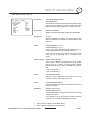
Preset, Pattern, Scan, Group, Privacy Mask, Schedule and More…
z
MAX. 127 Presets are assignable. All of them have independent characteristics such as White
Balance, Auto Exposure, Label, Alarm Input/Output and so on.
z
Max. 8 set of Scan can be stored. This enables to move camera repetitively between two preset
positions with designated speed.
z
Max. 4 of Patterns can be recorded and played back. This enables to move camera to follow any
trajectory operated by joystick as closely as possible.
z
Max. 8 set of Group action can be stored. This enables to move camera repetitively with
combination of Preset or Pattern or Scan. A Group is composed of max. 20 entities of
Preset/Pattern/Scans.
z
Max 8 Privacy Masks can be set up to protect privacy of other people.
z
7 rules of Schedule can be assigned by day and time. Appropriate actions (such as Home, Preset,
Group, Pattern and Scan) can be defined for each rule. Also, it is possible to use Weekday and All
days to simplify the rule.
ANTI-VANDAL 30x, 36x, 37x IP SPEED DOME CAMERA
6/27
INTRODUCTION
1
PTZ(Pan/Tilt/Zoom) Control
z
With RS-485 communication, max. 255 of cameras can be controlled at the same time.
z
Pelco-D/ Pelco-P/ Samsung protocol can be selected as a control protocol in the current version of
firmware.
OSD(On Screen Display) Menu
z
OSD menu is provided to display the status of camera and to configure the functions interactively.
z
The information such as Camera ID, Pan/Tilt/Zoom/Direction, Alarm Input & Output, date/time,
current temperature and Preset can be displayed on screen.
z
Each display item can be turned on or off independently.
Alarm I/O Functions
z
8 alarm sensor Inputs and 4 relay output are available.
z
To reject external electric noise and shock perfectly, alarm sensor Input is decoupled with photo
coupler.
z
The signal range of sensor input is from DC 5.0 to 12.0 volts to adopt various applications.
z
If an external sensor is activated, camera can be set to move to the corresponding Preset position.
z
Relay outputs can be assigned to work with a certain preset.
Reserved Presets for Special Purpose
z
Most of camera settings are directly changed by calling Reserved Presets, not entering into OSD
menu. For more information, refer to “Reserved Presets” in page 18 of this manual.
ANTI-VANDAL 30x, 36x, 37x IP SPEED DOME CAMERA
7/27
INTRODUCTION
1
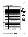
Product & Accessories
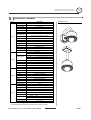
Product
z Wall Mount Type
z Ceiling Mount Type
Accessories
Hexagonal wrench
Water proof tape
Hole Template
Anchor bolts (4pcs)
Housing Safety Cable
Hanger
Instruction Manual
Safety Cable
Crossover Cable
ANTI-VANDAL 30x, 36x, 37x IP SPEED DOME CAMERA
8/27
INTRODUCTION
1
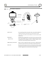
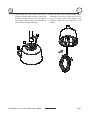
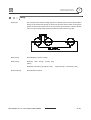
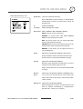
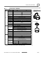
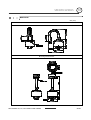
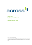
Parts Name & Functions
SUN SHIELD &
UPPER HOUSING
PTZ MECHANISM
DOME SAFETY CABLE
FAN
INNER BOX
FAN/HEATER CABLE
HEATER
DOME COVER
z Dome Cover
HOUSING SAFETY CABLE
HANGER
Do not detach protection vinyl from dome cover before finishing all
installation process to protect dome cover from scratches or dust.
In the dome cover, there are Fan and Heater to remove moisture on the
bubble dome.
z Sunshield &
Upper housing
Sunshield protect bubble dome cover from the sun rays and rain fall
from. In the sunshield, there is the upper housing which will contain
accommodate PTZ mechanism. Also, the upper housing will be
connected to both mounting brackets and dome cover.
z Wall/Ceiling mount Bracket
These are used to install the camera on the wall or ceiling and have
junction box. The junction box of the bracket accommodate inner box.
z Inner box
The inner has many important roles of connection box between camera
and outside. Top of the box, there are dip switches and terminal blocks
for Power supply, Video, Communication, Alarm Input/output.
ANTI-VANDAL 30x, 36x, 37x IP SPEED DOME CAMERA
9/27
2
INSTALLATION
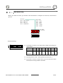
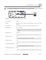
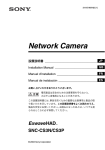
DIP Switch Setup
Before you install the camera, you should set the DIP switches to configure the camera ID, communication
protocol.
Protocol
0x00 : Auto Select
0x01 : Pelco-D
0x02 : Pelco-P
0x03 : SAMSUNG
0x04 : VCLTP
0x05 : KD6
Buad Rate
0x00
0x01
0x02
0x03
0x04
:
:
:
:
:
2400
4800
9600
19200
38400
RS-485
Terminate
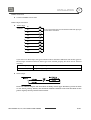
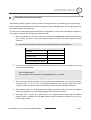
ID Setting (1~255)
Camera ID Setup
ON
z
ON
ID number of camera is set using binary number. The example is
shown bellow.
1
2
3
4
5
6
7
8
Pin
1
2
3
4
5
6
7
8
ID Value
1
2
4
8
16
32
64
128
ex) ID=5
on
off
on
off
off
off
off
off
ex) ID=10
off
on
off
on
off
off
off
off
z
The range of ID is 0~255. Factory default of Camera ID is 1.
z
If you want to control a certain camera, you must match the camera
ID with Cam ID setting of DVR or Controller.
ANTI-VANDAL 30x, 36x, 37x IP SPEED DOME CAMERA
10/27
2
INSTALLATION
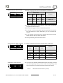
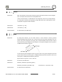
Communication Protocol Setup
ON
z
Select the appropriate Protocol with DIP switch combination.
Switch State
ON
1
2
3
4
5
6
7
Protocol
Pin1
Pin2
Pin3
Pin4
OFF
OFF
OFF
OFF
Auto Protocol
ON
OFF
OFF
OFF
PELCO-D
OFF
ON
OFF
OFF
PELCO-P
ON
ON
OFF
OFF
SAMSUNG
8
z
If you set the protocol as Auto Protocol, camera will automatically
recognize the kind of Protocol.
z
z
Auto Protocol supports Pelco-D and Samsung Protocol.
If you want to control using DVR or system keyboard, their protocol
must be identical to camera. Otherwise, you can not control the
camera.
z
If you changed camera protocol by changing DIP S/W, the change
will be effective after you reboot the camera.
Communication Baud rate Setup
ON
Factory default of protocol is “Auto Protocol
z
Select the appropriate Baud rate with DIP switch combination.
ON
1
Switch State
2
3
4
5
6
7
8
RS-485 Termination Resistor
ON
z
Protocol
Pin5
Pin6
Pin7
OFF
OFF
OFF
2400 BPS
ON
OFF
OFF
4800 BPS
OFF
ON
OFF
9600 BPS
ON
ON
OFF
19200 BPS
OFF
OFF
ON
38400 BPS
z
Factory default of Baud rate is “9600 BPS”
z
Pin 8 is used for ON/OFF of RS-485 Termination. Normally, it must be
OFF state. Especially when you have trouble with long Daisy chain
ON
style connection, turn ON this termination switch of last camera.
1
2
3
4
5
6
7
8
~ Pin 8
ANTI-VANDAL 30x, 36x, 37x IP SPEED DOME CAMERA
RS-485 Termination Resistor (On/Off)
11/27
INSTALLATION
2
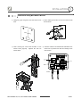
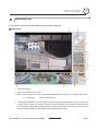
Installation using Wall Mount Bracket
① Using the paper template, mark the holes on the
wall.
into the holes.
③ After locating the wall mount bracket on the
anchor bolts properly.
② After drilling the holes, fix the four anchor bolts
Tighten the nuts for
anchor bolts
④ Connect cables to terminal blocks and BNC in the
inner box of junction box. See the cabling in the
next section.
RS-485
PTZ CONTROL
ALARM I/O
AUDIO
(IP Version)
POWER
INTERNET
(IP Version)
ANTI-VANDAL 30x, 36x, 37x IP SPEED DOME CAMERA
BNC
VIDEO
12/27
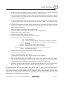
2
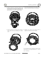
⑤ After hooking the safety cable on the hole of
⑥ Open the dome cover to install the PTZ camera
pipe [1], attach the upper housing to wall mount
mechanism. Care must be taken dome cover is
bracket by turning it at least seven turns [2]. To
hung by internal safety cable properly. Plug
fix the upper body orientation, turn the handle of
fan/heater cables into the connectors in the
double nuts to clockwise tightly [3].
housing.
ANTI-VANDAL 30x, 36x, 37x IP SPEED DOME CAMERA
13/27
2
INSTALLATION
⑦ Plug the connector of cable from junction box
into properly. After checking the orientation of one
touch connector in the upper housing, press the
PTZ mechanism into hook in the upper housing.
⑧ To lock the PTZ mechanism to the upper housing,
⑨ Close the dome cover. Care must be taken to
⑩ Tighten four screws on the dome cover in
press the two black handles till it sounds snap.
locate dome cover by matching the “Arrow”
sequence as shown in the picture bellow.
mark.
4
1
2
3
a
To maintain the best sealing, the torque of each
screw must be in the range between 0.5 ~ 1.0 N·m
(0.37 ~ 0.73 lbf·ft).
ANTI-VANDAL 30x, 36x, 37x IP SPEED DOME CAMERA
14/27
2
INSTALLATION
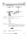
Cabling
Protocol Baudrate
Termination
Address
Controller/DVR
RS-485
RS-485
ALARM OUTPUT
ALARM OUTPUT
1
2
3
ALARM INPUT
1 2 3 4
G 5 6
4
1
7 8
2
3
4
ALARM INPUT
AC 24V
D+ D- D- D+
D+ D- D- D+
ES
E
T
PW
LI R
N
AC K
T
1 2 3 4 G 5 6 7 8
R
POWER
AUDIO
ET
PW
LI R
N
AC K
T
IN
R
ES
OUT
AUDIO
IN
BNC
OUT
INTERNET
Power Connection
z
Please, check the voltage and current capacity of rated power carefully. Rated power is indicated in the
back of main unit.
Rated Power
Input Voltage Range
Current Consumption
AC 24V
AC 19V ~29V
2.5 A
RS-485 Communication
z
For PTZ control, connect this line to keyboard and DVR. To control multiple cameras at the same time,
RS-485 communication lines of them is connected in parallel as shown below.
ANTI-VANDAL 30x, 36x, 37x IP SPEED DOME CAMERA
15/27
INSTALLATION
2
Video Connection
z
Connect with BNC coaxial cable.
Alarm Input Connection
z
Sensor Input
IN 1
INTERNAL
a It is noted that short circuit between GND and Input pin
means alarm activation.
IN 2
IN 3
IN 4
GND
IN 5
IN 6
IN 7
IN 8
If you want to use Alarm Input, the types of sensor must be selected in OSD menu. The sensor types are
Normal Open and Normal Close If sensor type is not selected properly, the alarm can be activated
reversely.
z
~ Normal Open (N.O)
Output Voltage is high state when sensor is activated
~ Normal Close(N.C)
Output Voltage is high state when sensor is not activated
Alarm Output
There are 4 Alarm Outputs and all of them are Relay contact type. Therefore, you do not have
to care about polarity, AC/DC, and isolations between channels. Care must be taken for the
power capacity of relay contact written above.
ANTI-VANDAL 30x, 36x, 37x IP SPEED DOME CAMERA
16/27
3
OPERATION
Check points before operation
z
Before power is applied, please check the cables carefully.
z
The camera ID of the controller must be identical to that of the camera to be controlled. The camera ID can
be checked in the System Information of OSD Menu.
z
If your controller supports multi-protocols, the protocol must be changed to match to that of the camera.
z
If you changed camera protocol by changing DIP switch, the change will be effective after you reboot the
camera.
z
Since the operation method can be different for each controller available, refer to the manual for your
controller if camera can not be controlled properly.
Preset and Pattern Function Pre-Check
z
Check how to operate Preset, Group, Scan and Pattern function with controller or DVR in advance to operate
camera function using them. (refer to your System keyboard Manual)
z
If controller or DVR has no pattern button or function, use shortcut keys with preset numbers. For more
information, refer to “Reserved Preset” in this manual.
ANTI-VANDAL 30x, 36x, 37x IP SPEED DOME CAMERA
17/27
3
OPERATION
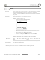
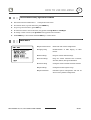
Starting OSD Menu
z Function
Using the OSD menu, Preset, Pattern, Scan, Group and Alarm Input function can be
configured for each application.
z Enter Menu
<Go Preset> [95]
Reserved Preset
z Description
z Function
Some Preset numbers are reserved to special functions.
<Go Preset> [95]
: Enters into OSD menu
<Go Preset> [131~134]
: Runs Pattern Function 1 ~ 4
<Go Preset> [141~148]
: Runs Scan Function 1 ~ 8
<Go Preset> [151~158]
: Runs Group Function 1 ~ 8
<Go Preset> [161~164]
: Sets Relay 1~4 Output to OFF
<Set Preset> [161~164]
: Sets Relay 1~4 Output to ON
<Go Preset> [170]
: Sets Camera BLC Mode to OFF
<Go Preset> [171]
: Sets Camera BLC Mode to HIGH
<Go Preset> [174]
: Sets Camera Focus Mode to AUTO
<Go Preset> [175]
: Sets Camera Focus Mode to Manual
<Go Preset> [176]
: Sets Camera Focus Mode to SEMI-AUTO
<Go Preset> [177]
: Sets Day & Night Mode to AUTO1
<Go Preset> [178]
: Sets Day & Night Mode to NIGHT
<Go Preset> [179]
: Sets Day & Night Mode to DAY
<Go Preset> [190]
: Sets OSD Display Mode to AUTO (Except Privacy Mask)
<Go Preset> [191]
: Sets OSD Display Mode to OFF (Except Privacy Mask)
<Go Preset> [192]
: Setting OSD Display Mode to ON (Except Privacy Mask)
<Go Preset> [193]
: Sets all Privacy Mask Display to OFF
<Go Preset> [194]
: Sets all Privacy Mask Display to ON
<Go Preset> [167]
: Zoom Proportional Jog ON
<Set Preset>[167]
: Zoom Proportional Jog OFF
<Go Preset>[200]
: Digital Zoom ON
<Go Preset>[201]
: Digital Zoom OFF
ANTI-VANDAL 30x, 36x, 37x IP SPEED DOME CAMERA
18/27
PRESET 127
3
OPERATION
127
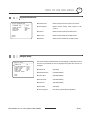
Preset
z Function
Max. 127 positions can be stored as Preset position. The Preset number can be assigned
from 1 to 128, but 95 is reserved for starting OSD menu.
Camera characteristics (i.e. White Balance, Auto Exposure) can be set up independently
for each preset and they are adjusted by using OSD menu. Four relay outputs can be
controlled in conjunction with one Preset.
z Set Preset
<Set Preset> [1~128]
z Run Preset
<Go Preset> [1~128]
z Delete Preset
To delete Preset, use OSD menu.
Scan
z Function
By using Scan function, you can make camera to move between 2 Preset positions
repeatedly. When Scan function runs, camera moves from the preset assigned as the 1st
point to the preset assigned as the 2nd point in CW(Clockwise) direction. Then camera
moves from the preset assigned as the 2nd point to the preset assigned as the 1st point in
CCW(Counterclockwise) direction.
In case that the preset assigned as the 1st point is same as the preset assigned as the 2nd
point, camera turns on its axis by 360° in CW(Clockwise) direction and then it turns on its
axis by 360° in CCW(Counterclockwise) direction.
Speed can be set up from 1°/sec to 180°/sec.
z Set Scan
To set Scan, use OSD menu.
z Run Scan
Method1) <Run Scan> [Scan NO.] [Enter]
Method2) <Go Preset> [Scan NO.+140]
z Delete Scan
ex) Run Scan 2 : <Go Preset> [142]
To delete Scan, use OSD menu.
ANTI-VANDAL 30x, 36x, 37x IP SPEED DOME CAMERA
19/27
OPERATION
4
3
Pattern
z Function
Pattern Function is that a camera memorizes the path (mostly curve path) by joystick
of controller for assigned time and revives the path exactly as it memorized.
4 Patterns are available and Maximum 1000 communication commands can be stored
in a pattern.
z Set Pattern
Pattern can be created by one of following two methods.
Method 1) <Set Pattern> [Pattern NO.]
{
Pattern editing screen is displayed as bellow.
{
Movement by Joystick and preset movement can be memorized in a pattern.
{
The rest memory size is displayed in progress bar.
{
To save the recording, press NEAR key and to cancel, press FAR key.
Method 2) OSD Using OSD Menu: See the section “How to use OSD Menu”.
z Run Pattern
Method 1) <Run Pattern> [Pattern NO.] ex) Run Pattern 2 : <Run Pattern> [2]
[Enter]
[Enter]
Method 2) <Go Preset> [Pattern NO.+130] ex) Run Pattern 2: <Go Preset> [132]
z Delete Pattern
Use OSD menu to delete a Pattern.
a When the pattern is saved or executed, the PAN/TILT is operated with Auto Flip OFF mode.
ANTI-VANDAL 30x, 36x, 37x IP SPEED DOME CAMERA
20/27
SCAN 8
3
OPERATION
Group
z Function
The Group function allows running sequence of Presets, Pattern and/or Scans. Max 8
Group can be stored. Each Group can have max 20 action entities which can be preset,
pattern or Scan. Preset speed can be set up and the repeat number of Pattern & Scan
can be set up in Group setup. Dwell time between actions can be set up also.
z Set Group
Use OSD Menu to create a Group.
z Run Group
Method1)
<Run
Group>
[Group
NO]
[Enter]
Method2) <Go Preset> [Group NO.+150]
z Delete Group
ex) Run Group 7 : <Go Preset> [157]
Use OSD Menu to delete.
ANTI-VANDAL 30x, 36x, 37x IP SPEED DOME CAMERA
21/27
3
OPERATION
Schedule
z Function
The Schedule function allows running an appropriate function like Preset, Scan, Group,
Pattern, Home move at designated day and time. For example, if you setup a rule
Tuesday at 9:00AM and Preset 1 (say Main Gate), the camera will move to main gate
every Tuesday at 9:00AM. If you choose Weekday, camera will move to Main gate
everyday except weekend.
It is noted that due to the real time clock, the time data will be kept regardless of
blackout. The initial time and day setup is essential to proper Schedule function.
z Set Schedule
Use OSD Menu to create a Schedule
z Run Schedule
Use OSD Menu of Schedule Master Enable
z Delete Schedule
Use OSD Menu to delete.
ANTI-VANDAL 30x, 36x, 37x IP SPEED DOME CAMERA
22/27
3
OPERATION
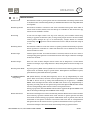
Other Functions
z Preset Lock
This function is made to protect preset data from unauthorized overwriting. If Preset Lock
is ON, Preset save command using Hot Key is disabled while Preset save using OSD Menu
is acceptable.
z Power Up Action
This function enables to resume the last action executed before power down. Most of
actions such as Preset, Pattern, Scan and Group are available for this function but Jog
actions are not available to resume.
z Auto Flip
In case that tilt angle arrives at the top of tilt orbit (90°), zoom module camera keep
moving to opposite tilt direction (180°) to keep tracing targets. As soon as zoom module
camera passes through the top of tilt direction(90°), images should be reversed
automatically and F appears in screen. If this function is set to OFF, tilt movement range is
0 ~ 90°.
z Parking Action
This function enables to locate the camera to specific position automatically if operator
doesn’t operate the controller for a while. The Park Time can be defined as an interval
from 5 seconds to 4 hours.
z Alarm Input
8 Alarm Inputs are used. If an external sensor is activated, camera can be set to move to
corresponding preset position. It is noted that the latest alarm input is effective if multiple
sensors are activated.
z Alarm Output
There are 4 Ch. of Alarm Outputs and all of them can be assigned to a certain Preset
number. For example, if you assign Preset 5 to AO2, calling Preset 5 result in turning On of
AO2.
z Privacy Zone Mask
To protect privacy, MAX. 8 Privacy Masks can be created on the arbitrary position to hide
objects such as windows, shops or private house. With Spherical Coordinates system,
powerful Privacy Zone Mask function is possible.
z GENERAL/SPECIAL
Image Setup
WB (White Balance) and AE (Auto Exposure) can be set up independently for each
preset. There are 2 modes, "General" mode & "Special" mode. The General mode means
that WB or AE can be set up totally and simultaneously for all presets in " CAMERA
SETUP" menu. The Special mode means that WB or AE can be set up independently or
separately for each preset in each preset setup menu. Each Special WB/AE value should
activate correspondingly when camera arrives at each preset location.
During jog operation, General WB/AE value should be applied. All Special WB/AE value
will not be changed although General WB/AE value change.
z Semi Auto Focus
This mode exchanges focus mode automatically between Manual Focus mode and Auto
Focus mode by operation. Manual Focus mode activates in preset operation and Auto
Focus mode activates during jog operation. With Manual mode at presets, Focus data is
memorized in each preset in advance and camera calls focus data in correspondence
with presets as soon as camera arrives at a preset. It should shorten time to get focuses.
Focus mode changes to Auto Focus mode automatically when jog operation starts.
ANTI-VANDAL 30x, 36x, 37x IP SPEED DOME CAMERA
23/27
3
OPERATION
OSD Display of Main Screen
z
P/T/Z Information
Current Pan/Tilt angle in degree, zoom magnification and a compass direction.
z
Camera ID
Current Camera ID(Address).
z
Action Title
Followings are possible Action Titles and their meaning.
"SET PRESET ×××"
"PRESET ×××"
"PATTERN ×"
"AUP×/PRESET ×××"
"UNDEFINED"
z
Preset Label
The Label stored for specific Preset.
z
Alarm Information
This information shows current state of Alarm Input. The “I” means Input and “O” is
output. If an Input is ON state it will show the number of input. If an Input is OFF state,
'-' will be displayed. In the same way “O:1” means output 1 is ON “O:-“ is OFF.
Ex) When Point 2 of inputs are ON, and Output 1 is On, OSD will show as below
z
Image Flip
Shows that images are currently reversed by Auto Flip Function.
z
Date/Time
Displays Current Date and Time.
ANTI-VANDAL 30x, 36x, 37x IP SPEED DOME CAMERA
24/27
4
HOW TO USE OSD MENU
General Rules of Key Operation for Menu
z
The menu items surrounded with <
> always has its sub menu.
z
For all menu level, to go into sub menu, press NEAR key.
z
To go to up-one-level menu, press FAR key.
z
To move from items to item in the menu, use joystick in the Up/Down or Left/Right.
z
To change a value of an item, use Up/Down of the joystick in the controller.
z
Press NEAR key to save values and Press FAR key to cancel values.
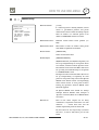
Main Menu
z System Information
Shows info and current configuration.
z Display Setup
Enable/Disable of OSD display on Main
Screen.
z Motion Setup
Setup for motion related settings
z Function Setup
Setup for various functions such as Preset,
Auto Pan, Pattern, Group and Schedule.
z Camera Setup
Configure Camera related functions and data
z System Setup
Configure for Basic system setup.
z System Initialize
Initializes system configuration and sets all
data to factory default configuration.
ANTI-VANDAL 30x, 36x, 37x IP SPEED DOME CAMERA
25/27
4
HOW TO USE OSD MENU
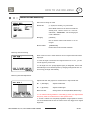
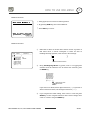
System Information
SYSTEM INFORMATION
-------------------------FIRMWARE VER
1.011P
COLOR SYSTEM
NTSC
PROTOCOL
SAMSUNG
BAUD RATE
9600
ADDRESS
255
BACK
EXIT
z Firmware Ver.
z Color System
Shows current firmware version of camera.
Shows current analog video system of the
camera.
z Protocol
Shows current Protocol for PTZ control
z Baud rate
Shows current Baud rate of PTZ control.
z Address
Shows current Camera ID for PTZ control.
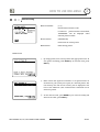
Display Setup
DISPLAY SETUP
-------------------------CAMERA ID
ON
PTZ INFORMATION AUTO
ACTION TITLE
AUTO
RESET LABEL
AUTO
ALARM I/O
AUTO
DATE/TIME
ON
<PRIVACY ZONE>
BACK
EXIT
This menu defines Enable/Disable of OSD display on Main Screen. If an
item is set to be AUTO, the item is displayed only when the value of it is
changed.
z Camera ID
[ON/OFF]
z PTZ Information
[ON/OFF/AUTO]
z Action Title
[ON/OFF/AUTO]
z Preset Label
[ON/OFF/AUTO]
z Alarm I/O
[ON/OFF/AUTO]
z Date/Time
[ON/OFF]
z <Privacy Zone>
Start Privacy Zone Mask setup Menu.
ANTI-VANDAL 30x, 36x, 37x IP SPEED DOME CAMERA
26/27
4
HOW TO USE OSD MENU
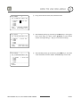
PRIVACY ZONE MASK Setup
Select area in image to mask.
z Mask No
[1~8] 36x, 37x model, [1~4] 30x model
Select Mask number. If the selected mask has
already data, camera moves as it was set.
Otherwise, “UNDEFINED” will be displayed
under “Mask NO”.
z Display
[ON/OFF]
Sets if camera makes mask shows or not on
images.
z Clear Mask
[CANCEL/OK]
Deletes data in the selected mask NO.
Privacy Zone Area Setup
Move camera to area to mask. Then the menu to adjust mask size will be
displayed.
a If the tilt angle is located in the range between 70° to 110°, you can
not set up privacy zone mask.
a If tilt angle over 110° (image flipped region) is designated, camera will
automatically move to identical poison by changing tilt angle less than 70°
and moving pan angle 180 relatively.
Privacy Zone Size Adjustment
Adjust mask size. Use joystick or arrow buttons to adjust mask size.
z (Left/Right)
Adjusts mask width.
z (Up/Down)
Adjusts mask height.
z Zoom In/Out
Change Color of mask (PTI-M300, M302 Only).
a It is noted that during PAN/TILT control like jog action, the object behind
the privacy mask can be disclosed in a short period of time.
a To hide a certain zone completely regardless of high speed PT motions,
it is recommended that the size of mask must be 20% bigger than original
target size
ANTI-VANDAL 30x, 36x, 37x IP SPEED DOME CAMERA
27/27
4
HOW TO USE OSD MENU
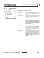
Motion Setup
Setup the general functions of Pan/Tilt motions.
z Preset Lock
[ON/OFF]
If Motion Lock is set to ON, it is impossible to set
up and delete Preset, Scan, Pattern and Group. It
is possible only to run those functions. To set up
and delete those functions, enter into OSD
menu.
z Power Up Action
[ON/OFF]
Refer to Other Functions section in Page 23.
z Auto Flip
[ON/OFF]
Refer to Other Functions section in Page 23.
z Jog Max Speed
[2°/sec ~200°/sec]
Sets maximum jog speed. Jog speed is inversely
proportional
to
ratio
of
zoom. As
zoom
magnification goes up, pan/tilt speed goes
down.
z Jog Direction
[INVERSE/NORMAL]
If you set this to ‘Normal’, the view in the
screen is moving same direction with jog tilting.
If ‘Inverse’ is selected, the view in the screen
is moving reversely.
z Freeze in Preset
[ON/OFF]
At start point of preset movement, camera starts
freezing the image of start point. Camera keeps
displaying the image of start point during
preset movement and does not display the
images which camera gets during preset
movement. As soon as camera stops at preset
end point, camera starts displaying live images
which it gets at preset end point.
ANTI-VANDAL 30x, 36x, 37x IP SPEED DOME CAMERA
28/28
HOW TO USE OSD MENU
4
Parking Action Setup
If Park Enable is set to ON, camera runs assigned function automatically
if there is no PTZ command during assigned "Wait Time".
z Park Enable
[ON/OFF]
z Wait Time
[5 seconds ~ 4 hour]
The time is displayed with "hh:mm:ss" format
and you can change this by 1 sec unit.
z Park Action
[HOME/PRESET/PATTERN/AUTOPAN/GROUP]
Ex) If HOME is selected for Park Action,
camera will move to home position when there
is no PTZ command during assigned "Wait
Time.”
Alarm Input Setup
Match the Alarm sensor input to one of Preset positions. If an external
sensor is activated, camera will move to corresponding preset position
when this item is predefined.
z Alarm Type
[Normal OPEN(N.O) / Normal CLOSE](N.C)]
Sets sensor input type.
z Alarm Action
[NOT
USED/HOME/PRESET
1~128/GROUP
1~8, PATTERN1~4, GROUP 1~4]
For each Alarm input, you can assign
counteraction functions (Preset, Auto Pan,
Pattern, Group).
ANTI-VANDAL 30x, 36x, 37x IP SPEED DOME CAMERA
29/29
PRESET 127
AUTO PAN 8
SCAN 8
4
SCHEDULE
HOW TO USE OSD MENU
127
4
Function Setup
Configure 5 Special Functions with this menu
FUNCTION SETUP
-------------------------<PRESET SETUP>
<AUTO PAN SETUP>
<PATTERN SETUP>
<GROUP SETUP>
<SCHEDULE SETUP>
z Preset Setup
127 Presets from the number 1 to 128 can be
assigned excluding preset 95 reserved for
Menu.
z Auto Pan Setup
Up to 8 Auto Pans are available, which makes
camera to move slowly between two preset
BACK
EXIT
points.
z Pattern Setup
Up to 4 patterns can be stored in the dome.
In this function, path data created by manual
move of Joystick are recorded and you can
playback the identical path automatically
whenever required.
z Group Setup
Up to 8 Groups can be defined.
In a Group, max 20 entities are assigned from
any combinations of Preset/Auto Pan/Pattern.
If you run a Group, camera will execute each
entry sequentially.
z Schedule Setup
7 rules of Schedule can be assigned by day
and time. Appropriate actions (such as Home,
Preset, Auto Pan, Pattern and Group) can be
defined for each rule. Also, it is possible to
use Weekday and Weekend in a rule to make
it simple.
ANTI-VANDAL 30x, 36x, 37x IP SPEED DOME CAMERA
30/30
PRESET 127
127
4
HOW TO USE OSD MENU
PRESET Setup
PRESET SETUP
-------------------------PRESET NO.
1
z Preset Number
If a selected preset is already defined, camera
moves to pre-defined position and preset
<EDIT SCENE>
<EDIT LABEL> WINDOWS
CLR PRESET CANCEL
CAM ADJUST GENERAL
ALARM OUT
---BACK
EXIT
[1~128]
characteristics such as Label and Relay Outputs
show on monitor. If a selected preset is not
defined, “UNDEFINED” shows on monitor.
z Edit Preset Scene
Redefine current Preset scene position (i.e.
PTZ).
z Edit Preset Label
Edits Label to show on monitor when preset
runs. MAX. 10 alphabets are allowed.
z Clear Preset
[CANCEL/OK]
Delete current Preset data
z CAM Adjust
[GENERAL/SPECIAL]
WB(White Balance) and AE(Auto Exposure) can
be set up independently for each preset. There
are 2 modes, "General" mode & "Special" mode.
The General mode means that WB or AE can be
set up totally and simultaneously for all presets
in "CAMERA SETUP" menu.
The Special mode means that WB or AE can be
set up independently or separately for each
preset in each preset setup menu. Each Special
WB/AE value should activate correspondingly
when camera arrives at each preset location.
During jog operation, General WB/AE value
should be applied.
All Special WB/AE value should not change
although General WB/AE value changes. If
“Special’’ is selected, Menu to set WB/AE shows
on monitor.
z Alarm out
State of four alarm outputs can be freely
controlled in conjunction with Preset run. The
character “-“ means OFF state and the
number representing each bit means ON.
Ex) If it is set to be -23-, Output relay 2, 3 will be
ON and 1, 4 will be OFF, when you run this
Preset.
ANTI-VANDAL 30x, 36x, 37x IP SPEED DOME CAMERA
31/31
PRESET 127
127
HOW TO USE OSD MENU
4
Edit Preset Scene
1 Using joystick, move camera to desired position.
○
2 By pressing NEAR key, save current PTZ data.
○
3 Press FAR key to cancel.
○
Edit Preset Label
①
Edits label to show on monitor when camera arrives at presets. In
Edit Label menu, a reverse rectangular is cursor. As soon as
EDIT LABEL
- PRESET 1
-------------------------[█
]
---------1234567890 OK
ABCDEFGHIJ CANCEL
KLMNOPQRST
UVWXYZabcd
efghijklmn
opqrstuvwx
yz<>-/:. ³
finishing selecting alphabet, cursor moves to the next digit.
[
]
Current Cursor Position
②
Using Left/Right/Up/Down of joystick, move to an appropriate
character from the Character set. To choose that character, press
the NEAR key.
1234567890
ABCDEFGHIJ
KLMNOPQRST
UVWXYZabcd
efghijklmn
opqrstuvwx
yz<>-/:. ³
Back Space Char.
Space Char.
If you want to use blank, choose Space character (" "). If you want to
delete a character before, use back space character (" ←").
③
If you complete the Label editing, move cursor to "OK" and press
NEAR key to save completed label. To abort current change, move
cursor to "Cancel" and press NEAR key.
ANTI-VANDAL 30x, 36x, 37x IP SPEED DOME CAMERA
32/32
AUTO PAN 8
HOW TO USE OSD MENU
4
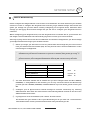
Scan Setup
SCAN SETUP
-------------------------SCAN NO.
1
1ST POS.
NOT USED
2ND POS.
NOT USED
z Scan Number
Selects Scan number to edit. If a selected Scan
has not defined, "NOT USED" is displayed in 1st
Position and 2nd Position
SCAN SPEED 30/SEC
CLEAR SCAN CANCEL
z 1st Position
BACK
EXIT
[1~8]
2nd Position
[PRESET 1~128]
Set up the 2 position for Scan function. If a
selected preset is not defined, "UNDEFINED" will
be displayed as shown below.
SCAN SETUP
-------------------------SCAN NO.
1
1ST POS.
PRESET5
2ND POS.
NOT USED
UNDEFINED
When scan function runs, camera moves from the
preset assigned as the 1st point to the preset
assigned as the 2nd point in CW(Clockwise)
direction. Then camera moves from the preset
assigned as the 2nd point to the preset assigned
as the 1st point in CCW(Counterclockwise)
direction. In case that the preset assigned as the
1st point is same as the preset assigned as the 2nd
point, camera turns on its axis by 360° in CW
direction and then it turns on its axis by 360° in
CCW direction.
z Scan Speed
[1°/sec ~180°/sec]
Sets Scan speed from 1°/sec to 180°/sec.
z Clear Scan
[CANCEL/OK]
Deletes current Scan data.
ANTI-VANDAL 30x, 36x, 37x IP SPEED DOME CAMERA
33/33
HOW TO USE OSD MENU
4
Pattern Setup
z Pattern Number
[1~4 ]
Selects Pattern number to edit.
If a selected
"UNDEFINED"
pattern number is not defined,
will
be
displayed
under
selected pattern number.
z Clear Pattern
[CANCEL/OK]
Deletes data in current pattern
z Edit Pattern
Starts editing pattern.
Edit Pattern
①
By using Joystick, move to start position with appropriate zoom. To
start pattern recording, press NEAR key. To exit this menu, press
FAR key.
②
Move camera with joystick of controller or run preset function to
memorize the path (mostly curve path) in a selected pattern. The
total memory size and the rest memory size is displayed in the
form of bar. Maximum 1,000 communication commands can be
stored in a pattern.
③ To save data and exit, press NEAR key. To cancel recording and
delete record data, press FAR key.
ANTI-VANDAL 30x, 36x, 37x IP SPEED DOME CAMERA
34/34
SCAN 8
HOW TO USE OSD MENU
4
Group Setup
GROUP SETUP
-------------------------GROUP NO.
1
UNDEFINED
CLEAR GROUP
CANCEL
<EDIT GROUP>
z Group Number
[1~8]
Selects Group number to edit.
If a selected Group number is not defined,
"UNDEFINED" will be displayed under selected
Group number.
BACK
EXIT
z Clear Group
[CANCEL/OK]
Deletes data in current Group
z Edit Group
Starts editing Group.
Edit Group
EDIT GROUP
1
-------------------------NO. ACTION NO. DWELL OPT
-------------------------1 NONE
2 NONE
3 NONE
4 NONE
5 NONE
-------------------------SAVE
CANCEL
[NEAR:EDIT]
EDIT GROUP
1
-------------------------NO. ACTION NO. DWELL OPT
-------------------------1 NONE
2 NONE
3 NONE
4 NONE
5 NONE
-------------------------SAVE
[NEAR:EDIT ACT]
CANCEL
[FAR :EDIT END]
EDIT GROUP
1
-------------------------NO. ACTION NO. DWELL OPT
-------------------------1 NONE
2 NONE
3 NONE
4 NONE
5 NONE
-------------------------SAVE
[ef:MOVE CURSOR]
CANCEL [cd:CHANGE VAL.]
① Press
Press Near
Near key
key in
in “NO”
“NO” list
list to
to start
start Group
Group setup.
setup.
②
Note
Note that
that MAX. 20 Functions are allowed in a Group. Move cursor
up/down
up/down and
and press
press Near
Near key
key to
to set
set up.
up.
③ Set
Set up
up Action, Dwell time and Option. Note that selected item is
displayed
displayed in
in reverse.
reverse. Move
Move cursor
cursor Left/Right to select items and
move
move cursor
cursor Up/Down
Up/Down to
to change
change each
each value.
value.
z Action ###
NO.
[NONE/PRESET/SWING/PATTERN]
[NONE/PRESET/SCAN/PATTERN]
z DWELL
[0 second ~ 4 minutes]
Sets Dwell Time between functions
z OPT
Option. ItIt represents
should bepreset
presetspeed
speed(2~360)
when
preset preset
when
is set isin selected.
Action. ItIt should
should be the
number of
of repetition
repeat when
(1~255)
Pattern
when
orPattern
Swing or
is
selected
Scan
is selected
in Action
for Action
ANTI-VANDAL 30x, 36x, 37x IP SPEED DOME CAMERA
35/35
SCAN 8
4
HOW TO USE OSD MENU
④
Set up items such as Action, NO., Dwell and OPT.
EDIT GROUP
1
-------------------------NO. ACTION ### DWELL OPT
-------------------------1 PRESET
1 00:03 360
2 NONE
3 NONE
4 NONE
5 NONE
-------------------------SAVE
[NEAR:EDIT ACT]
CANCEL
[FAR :EDIT END]
⑤
After finishing setting up an Action, press Near key to one-upper-
EDIT GROUP
1
-------------------------NO. ACTION ### DWELL OPT
-------------------------1 1 PRESET
1 00:03 360
2 NONE
3 NONE
4 NONE
5 NONE
-------------------------SAVE
CANCEL
⑥ After finishing setting up all Actions, press FAR key to exit. Then
EDIT GROUP
1
-------------------------NO. ACTION NO. DWELL OPT
-------------------------1 PRESET
1 00:03 360
2 NONE
3 NONE
4 NONE
5 NONE
-------------------------SAVE
[ef:MOVE CURSOR]
CANCEL [cd:CHANGE VAL.]
level menu (Step ②). Move cursor Up/Down to select Action
number and repeat Step ② ~ Step ④ to edit selected Group.
cursor should be moved to “SAVE.” Press Near key to save data.
ANTI-VANDAL 30x, 36x, 37x IP SPEED DOME CAMERA
36/36
4
HOW TO USE OSD MENU
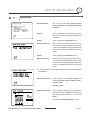
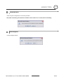
Schedule Setup
z Master Enable
SCHEDULE SETUP
-------------------------MASTER ENABLE
ON
DAY TIME
ACT NO
ON
1 UNDEFINED
2 UNDEFINED
3 UNDEFINED
4 UNDEFINED
5 UNDEFINED
6 UNDEFINED
7 UNDEFINED
BACK
[ON/OFF]
Decide whether Schedule function is active or not.
z Clear Schedule
[CANCEL/OK]
Delete all data in current Menu
z Edit Schedule
Start editing Schedule.
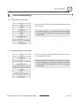
Edit Schedule
④ After move the Cursor to the number by using Up/Down keys,
SCHEDULE SETUP
-------------------------MASTER ENABLE
ON
DAY TIME
ACT NO
ON
1 UNDEFINED
2 UNDEFINED
3 UNDEFINED
4 UNDEFINED
5 UNDEFINED
6 UNDEFINED
7 UNDEFINED
BACK
press “Near”(Enter) Key to edit.
⑤
Each field can be selected by Left/Right keys and the values in
the field are changed using Up/Down keys.
The meaning of each value:
DAY
Days: MON > TUE > WED> THU > FRI > SAT > SUN
WKD: Weekday
SCHEDULE SETUP
-------------------------MASTER ENABLE
ON
DAY TIME ACT
NO
ON
1 MON 00:00 HOM
OFF
2 UNDEFINED
3 UNDEFINED
4 UNDEFINED
5 UNDEFINED
6 UNDEFINED
7 UNDEFINED
BACK
ALL: All days(Everyday)
TIME
24hour Format
ACT
PRS(Preset), SCN(Scan), PTN(Pattern), GRP(Group)
HOM(Home)
ON/OFF
Decide to make this rule effective or not
If you finish a rule, press Near key to select another rule.
Repeat this procedure to fill up the schedule in mind.
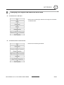
SCHEDULE SETUP
-------------------------MASTER ENABLE
ON
DAY TIME ACT
NO
ON
1 MON 01:20 HOM
ON
2 WEN 07:35 PRS
12
ON
3 THU 11:40 SCN
3
ON
4 SAT 15:17 PAT
1
ON
5 WEK 23:00 HOM
ON
6 UNDEFINED
7 UNDEFINED
BACK
⑥ Example: see left setup.
- The second rule means camera will move to Preset 12 position at
7:35 on every Wednesday.
* Note: If there are rules conflicts to each other, the higher number is,
the higher priority has.
* Note: If you assign undefined function, there will be no action.
* Hint: Using reserved Preset, you can make various schedules. For
example, PRS179 are PRS178 are Day and Night mode respectively.
(Refer to Reserved Presets in page 19 of this manual.)
ANTI-VANDAL 30x, 36x, 37x IP SPEED DOME CAMERA
37/37
WDR
432
HOW TO USE OSD MENU
4
CAMERA SETUP
Setup the general functions of zoom camera module
ZOOM CAMERA SETUP
-------------------------FOCUS MODE
SEMIAUTO
DIGITAL ZOOM
ON
IMAGE FLIP
OFF
FLICKERLESS
OFF
<WHITE BALANCE SETUP>
<AUTO EXPOSURE SETUP>
z Focus Mode
[AUTO/MANUAL/SEMIAUTO]
Sets camera focus mode.
{ SEMIAUTO Mode
This mode exchanges focus mode automatically
between Manual Focus mode and Auto Focus
mode. Manual Focus mode activates in preset
BACK
EXIT
operation and Auto Focus mode activates when jog
operation starts.
With Manual mode at presets, Focus data is
memorized in each preset in advance and camera
calls focus data in correspondence with presets as
soon as camera arrives at a preset.
z Digital Zoom
[ON/OFF]
Sets digital zoom function to ON/OFF. If this is set
to OFF, optical zoom function runs but zoom
function stops at the end of optical zoom
magnification.
z Image Flip
[ON/OFF]
To display Upside down image.
z Flickerless
[ON/OFF]
Turn on or off the Flickerless function. In this
function, AE mode becomes Shutter Priority mode
and shutter speed value will be fixed to 1/100 sec.
White Balance Setup
WB SETUP
-------------------------WB MODE
AUTO
zRED ADJUST
--zBLUE ADJUST
---
BACK
EXIT
z WB Mode
[AUTO/MANUAL]
In Manual mode, Red and Blue level can be
set up manually
z Red Adjust
[0~255]
z Blue Adjust
[0~255]
ANTI-VANDAL 30x, 36x, 37x IP SPEED DOME CAMERA
38/38
HOW TO USE OSD MENU
4
Auto Exposure Setup – 30x, 37x
AE SETUP - GLOBAL
-------------------------BACK LIGHT
OFF
DAY/NIGHT
AUTO
BRIGHT
25
IRIS
AUTO
SHUTTER
ESC
AGC
NORMAL
DNR
MIDDLE
SENS-UP
<AUTO>
BACK
EXIT
z Backlight
[OFF/HIGH/MIDDLE/LOW] *
[OFF/WDR/HLC] **
Sets Backlight related functions. Especially, HLC function
helps removing high light portion of image (like head
light beam in the dark) to get better contrast of the rest.
z Day/Night
[AUTO/DAY/NIGHT]
AUTO1 exchanges Day/Night mode faster than AUTO2.
z Brightness
[0~100]
Adjusts brightness of images. Iris, Shutter Speed and
Gain are adjusted automatically in correspondence with
this value.
z IRIS
[AUTO/MANUAL(0~100)] *
[AUTO/MANUAL(0~17)] **
If Iris is set to Auto, Iris should have highest priority in
adjusting AE and Shutter Speed should be fixed.
If Iris is set to Manual, Iris should be fixed and Iris has
lower priority in adjusting AE, in comparison with
others.
z Shutter Speed
[ESC/A. Flicker/Manual]
If Iris is set to Manual and Shutter Speed is set to ESC,
Shutter Speed should have highest priority. If Shutter
Speed is set to A. Flicker, to remove Flicker, Shutter
Speed should be set to 1/100 sec. for NTSC and 1/120 for
PAL.
(×128~1/120000 sec) *
(×256~1/120000 sec) **
z AGC
[OFF/NORMAL/HIGH]
Enhances image brightness automatically in case that
luminance level of image signal is too low.
z DNR
[OFF/LOW/MIDDLE/HIGH]
Enhances images by deducting noises when gain level of
images is too high.
z SENS-UP
[AUTO(2~128x)/OFF] *
[AUTO(2~256x)/OFF] **
Activates Slow Shutter function when luminance of image
(signal) is too dark.
It is possible to set up the maximum number of frames
piled up one on another by Slow Shutter function.
*
Note: Function or Range for PTI-M301 Model
** Note: Function or Range for PTI-M302 Model
ANTI-VANDAL 30x, 36x, 37x IP SPEED DOME CAMERA
39/39
4
HOW TO USE OSD MENU
Auto Exposure Setup – 36x
z WDR/BLC
[ ALL OFF / WDR ON / BLC ON ]
Select WDR(Wide Dynamic Range) or BLC(Backlight
Compensation) function. All OFF means turning off
both functions.
z
[AUTO/DAY/NIGHT]
Day/Night
AUTO exchanges Day / Night
z AE MODE
AUTO / MANUAL / IRIS / SHUTTER / BRIGHT
AUTO: Full Auto mode for AE function
MANUAL: In manual mode. IRIS, GAIN, SHUTTER
SPEED can be changed in this mode.
IRIS: Iris priority mode. You can change IRIS while
others are adjusted automatically.
SHUTTER: Shutter priority mode. Shutter speed can be
changed while others are adjusted automatically.
BRIGHT: In this mode, you can assign AE value in
terms of Brightness.
z IRIS
[Works when AE MODE is MANUAL or IRIS model]
Range: CLOSE/F1.6/F2/F2.4/F2.8/F3.4/F4/F4.8/F5.6/
F6.8/F8/ F9.6/F11/F14/F16/F19/F22/F28. (18 steps)
z GAIN
[Works when AE MODE is MANUAL]
Enhances image brightness automatically in case that
luminance level of image signal is too low.
Range: 3/0/2/4/6/8/10/12/14/16/18/20/22/24/26/28dB
(16 steps)
zShutter
[Works when AE MODE is MANUAL or SHUTTER mode]
Speed
1/1,1/2,1/4,1/8,1/15,1/30,1/60,1/90,1/100,1/125,1/180,
1/250,1/350,1/500,1/725,1/1000,1/1500,1/2000,1/4000,
1/6000,1/10000
zBrightness
[Works when AE MODE is BRIGHT]
Adjusts brightness of images. Iris, Shutter Speed and
Gain are adjusted automatically in correspondence
with this value. Range: 0~31 (32 steps)
ANTI-VANDAL 30x, 36x, 37x IP SPEED DOME CAMERA
40/40
4
HOW TO USE OSD MENU
System Setup
SYSTEM SETUP
-------------------------<DATE/TIME SETUP>
<RELAY TYPE>
<PASSWORD>
<SET HOME POSITION>
<SET NORTH DIRECTION>
LANGUAGE
ENGLISH
z SYSTEM SETUP
You can set up Date/Time, ALARM OUTPUT
RELAY, PASSWORD, HOME POSITION, NORTH
POSITION.
z DATE
Date is displayed in dd/mmm/yyyy format.
The day is automatically calculated when you
BACK
EXIT
set the date.
z TIME
Time is displayed in HH:MM:SS format.
z DATE/TIME Setup
After you press the Near key, each field can
be selected by Left/Right keys and the values
in the field are changed using Up/Down keys.
To save the updated data, press the Near key
again
z TIME
z DATE/TIME Setup
Time is displayed in HH:MM:SS format.
After you press the Near key, each field can
be selected by Left/Right keys and the values
in the field are changed using Up/Down keys.
To save the updated data, press the Near key
again
a It is noted that the range of date setup is limited from 01/JAN/2000 to
31/DEC/2037.
z RELAY TYPE SETUP
Contact types of 4 Ch. RELAY OUTPUTS are
defined. (NORMAL OPEN / NORMAL CLOSE)
NORMAL OPEN
NORMAL CLOSE
z PASSWORD SETUP
You can define 4 characters long password. If
this function is set to ENABLE, it is required to
type this password whenever to enter OSD
MENU.
It is noted that MASTER PSSWORD : “4321”
ANTI-VANDAL 30x, 36x, 37x IP SPEED DOME CAMERA
41/41
HOW TO USE OSD MENU
4
z SET HOME
HOME position means the origin of PAN angle
POSITION
calculation. The value of PAN angle displayed on
the screen is based on this HOME position.
By using Joystick, move the camera to the desired
position and press ENTER (NEAR/SAVE).
It is noted that Home is not effective to Tilt angle.
If you change the location of Home position, all
horizontal locations of functions such as preset,
pattern, Group, Scan, and privacy zone mask will be
shifted based on changed Home position.
z SET NORTH
DIRECTION
You can set up North direction.
By using Joystick, move the camera to the desired
NORTH position and press ENTER (NEAR/SAVE).
The direction will be displayed in the screen
[PAN AXIS / TILT AXIS / ZOOM / DD]
DD is direction and will be displayed from:
N/NE/E/SE/S/SW/W/NW
z LANGUAGE
You can select a preferred Language of OSD display
from 7 choices.
[ENGLISH/ESPAÑOL/FRANÇAIS/DEUTSCH/ITALIANO
/РУССКИЙ/PORTUGUÊS]
After selecting a language, press Enter(NEAR) key.
TIP: Set Home Position
When you replace the camera block or the orientation of camera is changed due to maintenance operations, it is
very difficult to maintain same pan orientation. Therefore, all function data depending on pan orientation such as
preset, pattern, Group, Scan, and privacy zone mask are not useful any more accordingly. However, even in this
case, you can reuse the data if you redefine Set Home Position on the previous Home position. It is
recommendable to memorize the target scene of current Home position.
ANTI-VANDAL 30x, 36x, 37x IP SPEED DOME CAMERA
42/42
HOW TO USE OSD MENU
4
System Initialize
z Clear All Data
Deletes all configuration data such as display,
camera, motion setup, and so on.
z Clear Display Set
Initializes Display Configuration
z Clear Camera Set
Initializes Camera Configuration
z Clear Motion Set
Initializes Motion Configuration
z Clear Function Se
Deletes Preset Data, Scan Data, Pattern Data,
Group Data and Schedule Data
z Reboot Camera
Reboots Zoom Camera module
z Reboot System
Reboots Speed Dome Camera
Initial Configuration Table
z Display Configuration
z Camera Configuration
Camera ID
ON
Focus Mode
SEMIAUTO
PTZ Information
AUTO
Digital Zoom
ON
Action Title
AUTO
Image Flip
ON
Preset Label
AUTO
White Balance
AUTO
Alarm I/O
AUTO
Backlight/BLC
ALL OFF
Date/Time
ON
Day/Night
AUTO
Privacy Zone
Undefined
AE Mode
AUTO
North Direction
Pan 0°
Iris Level
AUTO
Shutter
ESC
z Motion Configuration
AGC
NORMAL
Preset Lock
OFF
DNR
MIDDLE
Power Up Action
ON
SENS-UP
AUTO
Auto Flip
ON
Jog Max Speed
140°/sec
z Function Data
Jog Direction
NORMAL
Preset 1~128
Undefined
Freeze In Preset
OFF
Scan 1~8
Undefined
Park Action
OFF
Pattern 1~4
Undefined
Alarm I/O Action
OFF
Group 1~8
Undefined
Schedule 1~7
Undefined
z Communication Setup
Protocol
AUTO
Baud Rate
2400
ANTI-VANDAL 30x, 36x, 37x IP SPEED DOME CAMERA
43/43
NETWORK SETUP
5
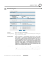
Quick Start of Network Connection
Please follow the steps below to complete the initial setup of the Network Function.
L Please do not power on the IP Speed Dome until instructed.
L Temporarily disable any proxy servers configured in Internet Explorer.
L If connecting the IP Speed Dome directly to a modem, power down and reset the modem.
Leave the modem powered down until configurations are finalized with the IP Speed Dome
and the IP Speed Dome has been correctly connected to the modem.
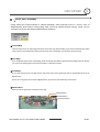
①
You will need to access a PC/laptop and should configure that PC in order to communicate
with the IP Speed Dome. Record the current TCP/IP properties of that PC (IP address, subnet
mask, gateway, DNS, etc)
L If your PC obtains its IP address automatically, then there is no need to record any
information.
②
Change the IP address of that host PC to 192.168.1.11 and subnet mask to 255.255.255.0 (leave
all other entries blank)
③
Connect the IP Speed Dome to your PC’s Ethernet port via the supplied crossover cable (it
does not matter what end is used for the PC)
④
Power on the IP Speed Dome using the supplied power adapter.
⑤
After 50 seconds of power, verify a flashing ACTIVE indicator, and a flashing or solid LINK
indicator. After the corresponding indicator lights are properly displayed, open Internet
Explorer.
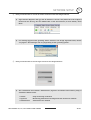
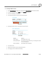
⑥
Type - http://192.168.1.80 (the default IP of the IP Speed Dome) into your address bar.
⑦
Default ID/Password to access IP Speed Dome are both the word: admin
⑧
Familiarize yourself with the Viewer Interface Screen.
⑨
Locate the TCP/IP configuration under Administration Tools. Supply the same ID and Password
to enter Administration Tools (admin:admin)
⑩
Under “Network Type” select STATIC. You will only select Dynamic or PPPoE if you are
connecting the IP Speed Dome directly to your cable/DSL/Broadband modem and your
Internet Service Provider is supplying you a dynamic or PPPoE address.
L If you have a network with other devices (such as PC/laptop, etc.) or a router, you will
NEVER select Dynamic or PPPoE.
ANTI-VANDAL 30x, 36x, 37x IP SPEED DOME CAMERA
44/44
5
NETWORK SETUP
⑪
Configure the IP Speed Dome’s TCP/IP settings as you would any other PC on your network,
providing a proper IP address, subnet mask, default gateway, and DNS server.
L If this is standalone unit with a direct connection to a cable/DSL/Broadband modem then
input the addresses you have received from your ISP. If you received no IP address from
your ISP, please select Dynamic or PPPoE and choose the proper settings.
⑫
The IP Speed Dome utilizes five TCP ports - a Web Server Port for utilizing Internet Explorer, a
Video Server Port, a Control Server Port, Audio ports. A Web Server Port is for utilizing
Internet Explorer, a Video Server port is to support the streaming video, and a Control Server
Port is to transmit to control command. Also Audio Port are to transmit and to receive Audio
data. If this IP Speed Dome will be directly attached to a cable/DSL/Broadband modem or has
been assigned a static IP from your ISP, then leave the default port settings. If you are installing
the IP Speed Dome on a network, you must define a Web Server Port other than 80. The other
ports, a Video Server Port, a Control server Port, Audio Ports can remain unchanged.
⑬
If the IP Speed Dome is connected to a network which utilizes a router, you must have Port
Forwarding configured on your personal router to forward all ports to the IP address you have
assigned the IP Speed Dome.
⑭
After configuring Port Forwarding on your router (if necessary), you may then access your IP
Speed Dome on your local network by opening Internet Explorer and specifying the IP
address and Web Server Port that you have assigned to the IP Speed Dome.
L Examples: http://192.168.0.200:8888 or http://24.106.88.123
L If you left your Web Server Port set to 80, then you don’t need to specify the port in the
Address Bar when accessing your IP Speed Dome.
⑮
Access your IP Speed Dome via the Internet :
If you used a static IP address assigned by your ISP
i) Open Internet Explorer.
ii) Type the IP of the IP Speed Dome.
iii) If you use a router, type the routers’ static IP and the web port number of the IP
Speed Dome.
If you have a dynamic address provided by your ISP
i) Open Internet Explorer and visit the DDNS website.
ii) Register the IP Speed Dome.
iii) Reboot the IP Speed Dome.
iv) Give the DDNS server 2 minutes to locate your IP Speed Dome’s IP information.
v) Click the refresh button in the Internet Explore.
vi) After your camera is connected, select your camera.
ANTI-VANDAL 30x, 36x, 37x IP SPEED DOME CAMERA
45/45
5
NETWORK SETUP
3
Initial Setup via a Crossover Cable
This section provides a guide on how to connect the IP Speed Dome to your PC/laptop for initial setup.
Please follow the instructions in the order they appear, without skipping steps. Do not supply power to
the IP Speed Dome, until instructed.
In order to access the IP Speed Dome’s firmware you will need to connect the Video Server directly to a
PC or laptop computer via the supplied crossover cable.
①
Before you begin, you must determine the current network/INTERNET (TCP/IP) settings on the
PC or laptop you plan to setup the IP Speed Dome. Jot down your entries below for quick
reference.
L For information on how to determine your currents settings, see Appendix A
Current TCP/IP Settings
IP Address
Subnet Mask
Default Gateway
Primary DNS Server
Secondary DNS Server (Option)
②
In order for the IP Speed Dome to communicate with your PC, you have to change your PC’s IP
address and subnet mask
L We recommend that you change your IP address to 192.168.1.11 and change the subnet
mask to 255.255.255.0
Leave all other entries (Default Gateway, DNS Servers, etc.) blank.
L For information on how to change your IP address and subnet mask, see Appendix B
③
After you have made the changes to your IP address and subnet mask, you may then attach the
IP Speed Dome to your PC via the supplied crossover cable. Plug-in either end of the
crossover cable into the PC’s network card and the other end into your IP Speed Dome.
④
After connecting the PC and IP Speed Dome using the crossover cable, power on the IP Speed
Dome by plugging in the power supply shipped with the IP Speed Dome.
⑤
No longer than 1 minute after powering on the IP Speed Dome, verify that the ACTIVE
indicator light is flashing, and the LINK indicator light is flickering or solid. If they are not,
please read the FAQ.
ANTI-VANDAL 30x, 36x, 37x IP SPEED DOME CAMERA
46/46
5
NETWORK SETUP
⑥
Now you will be able to access the viewer software within the IP Speed Dome.
L Open Internet Explorer and type the IP address of 192.168.1.80 (default IP of the IP Speed
Dome from the factory) into the Address Bar of the web browser (as seen below). Press
Enter.
L If a message appears after pressing “Enter” similar to the image depicted below, choose
“Try Again”. This message will vary depending on the operating system.
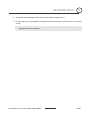
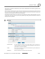
⑦
Now you will be able to see the login screen for the IP Speed Dome
L The 3 authorities are available : Administrator, Operator and Viewer. The authority setup is
available in Admin. Tools.
• Viewer
Only monitoring is allowed.
• Operator
Monitoring, PTZ Control and Digital In/Out Control are allowed.
• Administrator
All functions are allowed.
ANTI-VANDAL 30x, 36x, 37x IP SPEED DOME CAMERA
47/47
NETWORK SETUP
5
⑧
The default ID and Password are both the word “admin” (without the “”)
⑨
If at any time you are prompted to download ActiveX controls, you must click ‘Yes’, all content
is safe.
L You will have to click “Yes” twice to two individual prompts. This allows your video to be
displayed in Internet Explorer.
ANTI-VANDAL 30x, 36x, 37x IP SPEED DOME CAMERA
48/48
NETWORK SETUP
5
Guide to Network Setup
Please configure the IP Speed Dome at the location of its installation. You must determine your network
scenario in order to configure the IP Speed Dome with the proper TCP/IP settings. This tutorial will
guide you through the process. Before actually configuring the IP Speed Dome, determine what
settings you will apply. Record those settings that you will use to configure your IP Speed Dome for
reference.
When configuring your IP Speed Dome, treat the IP Speed Dome as another PC on your network. You
will assign it several addresses and other TCP/IP properties to match your current network.
This step-by-step tutorial will teach what IP addresses and network configurations you should assign
your IP Speed Dome based upon your network scenario.
①
Before you begin, you will need to locate any information and settings that you have received
from your Internet Service Provider (ISP). You may need to refer to these IP addresses at a later
time during the configuration.
L If you were not given any IP addresses or the ISP was responsible for the setup and
2
installation of your Internet connection on your PC or network, then please go to step ○
L If you are not using a router on your network, your “Current TCP/IP Settings” (from the
previous section) and “Assigned IP Addresses from My ISP” will be exactly the same
Assigned IP Address
IP Address
Subnet Mask
Default Gateway
Static
Primary DNS Server
Dynamic
Secondary DNS Server (Option)
PPPoE
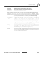
②
You must determine whether the IP address that you were assigned from the ISP is STATIC,
DYNAMIC, or using PPPoE. At this moment, you are only concerned about the ISP. Did they
provide you with a STATIC, DYNAMIC, or PPPoE address? If you are unsure, please contact your
ISP.
③
Configure your IP Speed Dome’s TCP/IP settings for network connectivity by selecting
Administration Tools from the main interface and selecting TCP/IP located on the left of the
Administration Tools screen.
④
If prompted for an ID and Password, use “admin” for both entries.
The default web port number is 80. If your ISP blocks port 80 you must use a value between
1025-30000. Please consult your ISP and determine if they block TCP port 80.
ANTI-VANDAL 30x, 36x, 37x IP SPEED DOME CAMERA
49/49
NETWORK SETUP
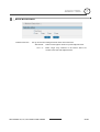
⑤
5
Depicted below are several basic network scenarios. Determine which scenario describes
your network. If your network does not match one of the scenarios below and are unsure how
to setup your IP Speed Dome, please contact your network administrator, then call our Support
Center.
L
Dash line box signifies areas of tour network that you can't control.
Only the ISP has access to these devices.
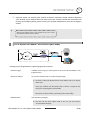
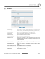
Case A : Dynamic IP or PPPoE + Personal Router [Most SOHO]
Configure your IP Speed Dome's TCP/IP properties as follows :
Network Type
• STATIC (even though you have Dynamic IP from your ISP, use STATIC on the
IP Speed Dome)
Internet Address
• A private IP address such as 192.168.0.200 [Example]
L You need to assign the IP Speed Dome an IP address, just as you would
assign a PC.
L The IP address you assign must be unique to your network as well as
match your network. For information how to choose a unique IP and
match your network please read the FAQ.
L The IP address you assign the IP Speed Dome must be a private IP. For
information on how to chose a private IP please read the FAQ
Subnet Mask
• 255.255.255.0 [Example]
L You must use the same subnet mask as the one you noted under
“Current TCP/IP Settings”
ANTI-VANDAL 30x, 36x, 37x IP SPEED DOME CAMERA
50/50
NETWORK SETUP
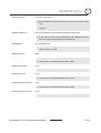
Default Gateway
5
• 192.168.0.1 [Example]
L This IP address must be the IP address of your router (private or LAN
side)
L Use the same Default Gateway you noted under “Current TCP/IP
Settings”
Primary DNS Server
• Use the 1st DNS Server from “Assigned IP Address from My ISP”
L If you did not receive any IP addresses from your ISP, please contact
them and acquire the IP address of their DNS server.
DDNS Server
• Use the DDNS server
L This is the same site you will register with later to accommodate
dynamic IP from your ISP.
Web Server Port
• 8888
L Do NOT use the default port 80, you must change this number.
L You may select any number between 1025 ~ 30000.
Control Server Port
• 7777
L You may select any number between 1025 ~ 30000.
Video Server Port
• 7778
L You may select any number between 1025 ~ 30000.
Audio Transmit Server Port
• 7779
L You may select any number between 1025 ~ 30000.
Audio Receive Server Port
• 7780
L You may select any number between 1025 ~ 30000.
ANTI-VANDAL 30x, 36x, 37x IP SPEED DOME CAMERA
51/51
NETWORK SETUP
5
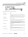
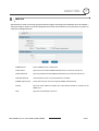
Case B : Static(Fixed) IP + Personal Router [Efficient]
Configure your IP Speed Dome's TCP/IP properties as follows :
Network Type
• STATIC
Internet Address
• A private IP address such as 192.168.0.200 [Example]
L You need to assign the IP Speed Dome an IP address, just as you would assign
a PC.
L The IP address you assign must be unique to your network as well as match
your network. For information how to choose a unique IP and match your
network please read the FAQ.
L The IP address you assign the IP Speed Dome must be a private IP. For
information on how to chose a private IP please read the FAQ
Subnet Mask
• 255.255.255.0 [Example]
L You must use the same subnet mask as the one you noted under “Current
TCP/IP Settings”
Default Gateway
• 192.168.0.1 [Example]
L This IP address must be the IP address of your router (private or LAN side)
L Use the same Default Gateway you noted under “Current TCP/IP Settings”
Primary DNS Server
• Use the 1st DNS Server from “Assigned IP Address from My ISP”
L If you did not receive any IP addresses from your ISP, please contact them and
acquire the IP address of their DNS server.
DDNS Server
• Use the DDNS server
L This is the same site you will register with later to accommodate dynamic IP
from your ISP.
ANTI-VANDAL 30x, 36x, 37x IP SPEED DOME CAMERA
52/52
NETWORK SETUP
Web Server Port
5
• 8888
L Do NOT use the default port 80, you must change this number.
L You may select any number between 1025 ~ 30000.
Control Server Port
• 7777
L You may select any number between 1025 ~ 30000.
Video Server Port
• 7778
L You may select any number between 1025 ~ 30000.
Audio Transmit Server Port
• 7779
L You may select any number between 1025 ~ 30000.
Audio Receive Server Port
• 7780
L You may select any number between 1025 ~ 30000.
ANTI-VANDAL 30x, 36x, 37x IP SPEED DOME CAMERA
53/53
5
NETWORK SETUP
Case C : Static(Fixed) IP [Dedicated line directly to the IP Speed Dome]
Configure your IP Speed Dome's TCP/IP properties as follows :
Network Type
• STATIC
Internet Address
• A static IP address received from your ISP, such as 24.107.88.125 [Example]
L You need to assign the IP Speed Dome an IP address, just as you would
assign a PC.
Subnet Mask
• Subnet mask assigned from your ISP, such as 255.255.255.240 [Example]
Default Gateway
• 24.107.88.113 [Example]
L Use the assigned default gateway from your ISP
Primary DNS Server
• Use the 1st DNS Server from “Assigned IP Addresses from My ISP”
L If you did not receive any IP addresses from your ISP, please contact
them and acquire the IP address of their DNS server.
DDNS Server
• Use the DDNS sever
L This is the same site you will register with later to utilize our DDNS
service.
Web Server Port
• 80 [default]
L You may select any number between 1025 ~ 30000.
Control Server Port
• 7777
L You may select any number between 1025 ~ 30000.
ANTI-VANDAL 30x, 36x, 37x IP SPEED DOME CAMERA
54/54
NETWORK SETUP
Video Server Port
5
• 7778
L You may select any number between 1025 ~ 30000.
Audio Transmit Server Port
• 7779
L You may select any number between 1025 ~ 30000.
Audio Receive Server Port
• 7780
L You may select any number between 1025 ~ 30000.
ANTI-VANDAL 30x, 36x, 37x IP SPEED DOME CAMERA
55/55
5
NETWORK SETUP
Case D : Dynamic IP + DSL/Cable Modem [Connected directly to the IP Speed Dome]
Configure your IP Speed Dome's TCP/IP properties as follows :
Network Type
• DYNAMIC
DDNS Server
• Use the DDNS server
L This is the same site you will register with later to accommodate dynamic
IP from your ISP.
Web Server Port
• 80 [default]
L You may select any number between 1025 ~ 30000.
Control Server Port
• 7777
L You may select any number between 1025 ~ 30000.
Video Server Port
• 7778
L You may select any number between 1025 ~ 30000.
Audio Transmit Server Port
• 7779
L You may select any number between 1025 ~ 30000.
Audio Receive Server Port
• 7780
L You may select any number between 1025 ~ 30000.
L When connecting the IP Speed Dome directly to a modem, power down and reset the modem.
Leave the modem powered down until configurations are finalized with the IP Speed Dome and the
IP Speed Dome has been correctly connected to the modem. Then power on the modem, followed
by the IP Speed Dome.
ANTI-VANDAL 30x, 36x, 37x IP SPEED DOME CAMERA
56/56
NETWORK SETUP
5
Case E : PPPoE + DSL Modem [Connected directly to the IP Speed Dome]
Configure your IP Speed Dome's TCP/IP properties as follows :
Network Type
• PPPoE
User ID
• Use the User ID or Username you received from your ISP for this direct
connection
User Password
• Use the Password you received from your ISP for this direct connection
DDNS Server
• Use the DDNS server
L This is the same site you will register with later to utilize our DDNS
service
Web Server Port
• 80 [default]
L You may select any number between 1025 ~ 30000.
Control Server Port
• 7777
L You may select any number between 1025 ~ 30000.
Video Server Port
• 7778
L You may select any number between 1025 ~ 30000.
Audio Transmit Server Port
• 7779
L You may select any number between 1025 ~ 30000.
Audio Receive Server Port
• 7780
L You may select any number between 1025 ~ 30000.
ANTI-VANDAL 30x, 36x, 37x IP SPEED DOME CAMERA
57/57
NETWORK SETUP
5
Port Forwarding
After entering the correct TCP/IP settings you will be ready for “Port Forwarding” (Cases A, B).
Please record the TCP/IP settings of your IP Speed Dome for future reference. You may need this
information to access your IP Speed Dome and to configure “Port Forwarding”.
IP Speed Dome TCP/IP Settings
IP Address
Subnet Mask
Default Gateway
Primary DNS Server
DDNS Server
Web Server Port
Control Server Port
Video Server Port
Audio Transmit Server Port
Audio Receive Server Port
After clicking “Apply” the system will prompt for a reboot. Please allow the system 50
seconds to reboot and accept the changes. After 50 seconds, close the configuration screen.
The view will display “Trying to Reconnect”. If the ACTIVE light on the IP Speed Dome has
gone off and is now back on again flashing, then the IP Speed Dome has rebooted. After the
system reboots completely, remove the power supply from the unit and close Internet
Explorer.
Return your PC/Laptop TCP/IP properties to their original settings.
Before installing the IP Speed Dome, you must use “Port Forwarding” on your personal router
(Cases A, B).
You will need to forward 5 ports:
• Web Server Port you assigned to the IP Speed Dome.
• Control Server Port you assigned to the IP Speed Dome.
• Video Server Port you assigned to the IP Speed Dome.
• Audio Transmit Server Port you assigned to the IP Speed Dome.
• Audio Receive Server Port you assigned to the IP Speed Dome.
Both of these ports will be forwarded to the IP address you assigned to the IP Speed Dome.
In the example above, you would forward:
• 8888 192.168.0.200
• 7778 192.168.0.200
• 7777 192.168.0.200
• 7779 192.168.0.200
• 7780 192.168.0.200
L For information on how to use “Port Forwarding” please read Appendix C
ANTI-VANDAL 30x, 36x, 37x IP SPEED DOME CAMERA
58/58
NETWORK SETUP
5
Starting IP Speed Dome
After correctly forwarding the Web Server Port , Video Server Port, Control Server Port and two Audio
Ports through your router (if applicable), you may then install the IP Speed Dome in a proper location.
①
Locate the serial number located on the label attached to the bottom of the IP Speed Dome,
you will need this for DDNS registration.
②
Connect the IP Speed Dome to your router or cable/DSL modem (per your network scenario)
via a Cat5/5e UTP Ethernet network cable.
③
Supply power to the IP Speed Dome.
④
After 50 seconds, verify the IP Speed Dome indicators:
⑤
⑥
• ACTIVE
Flashing
• LINK
Flickering/Solid
After configuring Port Forwarding on your router (if necessary), you may then access your IP
Speed Dome on your local network by opening Internet Explorer and specifying the IP
address and Web Server Port that you have assigned to the IP Speed Dome.
L
Examples: http://192.168.0.200:8888 or http://24.106.88.123
L
if you left your Web Server Port set to 80, then you don’t need to specify the port in the
Address Bar when accessing the IP Speed Dome.
Access your IP Speed Dome via the Internet:
If you use Case B or C
i) Open Internet Explorer.
ii) Type the IP of the IP Speed Dome.
If you use Case A, D, E
i) Open Internet Explorer.
ii) Visit the DDNS website.
iii) Register the IP Speed Dome.
iv) Give the DDNS server 10 minutes (MAX) to locate your IP Speed Dome’s IP
information. You may reboot the server to send an immediate request to our DDNS
server.
v) After your camera is connected, select your camera.
ANTI-VANDAL 30x, 36x, 37x IP SPEED DOME CAMERA
59/59
WEB VIEWER
6
Web Viewer Screen
In this section, the main GUI of the IP Speed Dome will be explained.
General Tab
3
○
4
○
2
○
5
○
6
○
7
○
8
○
9
○
10
○
11
○
12
○
13
○
14
○
1
○
15
○
17
○
16
○
19
○
20
○
18
○
1
○
Live video Display
2
○
OSD - Camera Name / Date / Time
3
○
OSD – In this location, level of user logged will be displayed. For example, ‘G’ means guest level of user.
• G = Guest User
4
○
: Video monitoring only
Virtual Joystick Handle for Pan/Tilt control. If you press and drag the handle in the center of circle, the
camera will be moved in accordance with your mouse movement. If you release the mouse button,
camera will be stopped and the handle will be relocated to the center of the circle. It is noted that the
speed will be proportional to the displacement of handle from the center.
ANTI-VANDAL 30x, 36x, 37x IP SPEED DOME CAMERA
60/60
WEB VIEWER
5
○
6
Zoom, Focus, and Iris controls for the camera connected to IP Speed Dome. If you drag the each handle,
Zoom, Focus, and Iris are adjusted individually according to your mouse motion.
6
○
Tap to switch General or Special function controls. The picture above shows controls when general
controls are selected. If you select special tab, you will have more controls such as Map Create, Motion
Detection, and Motion Tracking.
7
○
Controls for Presets memorized in the PTZ camera. It is noted that some PTZ devices may not support all
15 ,○
19 ) are supported by IP
of these functions and the Preset and Group functions created in the Map(○
Speed Dome.
8
○
Controls for Pattern, Swing and Group functions memorized in the PTZ camera. It is noted that some PTZ
devices may not support all of these functions and the Preset and Group functions created in the Map is
supported by IP Speed Dome.
9
○
Sensor Alarm Input status and Sensor Alarm Output control.
10
○
This button allows transmitting Audio stream from your MIC to IP Speed Dome.
11
○
Volume control for MIC in your computer.
12
○
Volume control for speaker out of your computer.
13
○
This button allows receiving Audio stream from IP Speed Dome.
14
○
Controls in this area has many functions such as;
X2 :
OSD :
Stretch :
2 times Digital Zoom.
It means “On Screen Display”. Click this button to display the captions.
Stretch will fit the video size to the viewer window regardless of
resolution.
Capture :
Admin Tool :
Connect/Disconnect :
Logout :
Click this button to save video as an image.
Click this button to enter Administration Tools.
Click this button to disconnect or connect from the server.
Click this button to logout.
15
○
show the Current Group number. The maximum number of group is 20.
16
○
15 ).
Click to run current group (shown in ○
17
○
Display current number of users connected as:
[Current number of users connected / maximum number of users connected].
18
○
15 .
Show the list of presets selected in the group in ○
19
○
Show the information of the preset stored before. The number in the yellow box is the preset number
and the number in the orange box means Dwell time. It is noted that the box size means view size of
corresponding preset. Accordingly, the smaller box size, the bigger zoom magnification.
20
○
This Screen is called map. This map data is normally stored in IP Speed Dome to share it with all clients.
By pressing appropriate button, you may download it from IP Speed Dome or create to update it.
As explained before, there are three kinds of user authority level i.e. guest, operator and administrator
and. It is noted that since the OSD display and Digital Zoom functions do not affect other users view but
only affect the current view, these functions can be changed to all user levels. However, since all other
functions affect to settings of the video server and accordingly video of all users connected, the user with
administrator level can change those functions.
ANTI-VANDAL 30x, 36x, 37x IP SPEED DOME CAMERA
61/61
WEB VIEWER
6
Special Tab
1
○
2
○
3
○
4
○
5
○
6
○
7
○
8
○
9
○
1
○
Tab to switch General controls.
2
○
Click it to create new map automatically. Before creating new map, please, make sure Camera model in
the “Motion Tracking” menu and PTZ Protocol in “Control” menu in the Admin Tool is correctly selected.
3
○
Click it to store map, presets and group data to the IP Speed Dome.
4
○
Click it to show or hide the preset box and label on the map.
5
○
Click it to download the map from IP Speed Dome.
6
○
This button activates or stops motion detection. “Detection Area setting” bellow must be done in
advance.
7
○
This button activates or stops motion detection target area setup mode. If you click this button, you will
see the green grids on the screen. To assign the target area, click the corresponding square on there
screen. The color of the square will be changed. To clear the selection, click again the square.
If you want to exit the setup mode, press this button again.
8
○
This defines the sensitivity of motion detection. Move small circular handle toward the+ direction to
increase the sensitivity.
9
○
Click it to turn Motion Tracking function on or off.
ANTI-VANDAL 30x, 36x, 37x IP SPEED DOME CAMERA
62/62
WEB VIEWER
6
Create, Save, Load Map
Firstly, make sure Camera Model in “Motion Tracking” menu and PTZ Protocol in “Control” menu of
Administration Tools before creating Map. Also, most map related function except “Load” can be
operated only by the user who has Administrator authority.
Create Map
Click [Create] button to make IP Speed Dome create new map automatically. If you control something else when
map is created, that will disturb creating work. In this case, accordingly, you will have inaccurate map.
Save Map
If you click [Save] button, the current Map, Preset and Group data will be uploaded to the IP Speed Dome. By this,
you can use stored map data in the future and share it with other Clients.
Load Map
If you click [Load] button, the Map, Preset and Group data stored previously will be downloaded from the IP
Speed Dome.
If there is no map data stored in the IP Speed Dome, you will see only black map in the screen.
Show Labels
Show or hide the preset box and label on the map.
Preset Number
Dwell Time
Preset View Area
ANTI-VANDAL 30x, 36x, 37x IP SPEED DOME CAMERA
63/63
WEB VIEWER
6
Preset
If you draw a box on the map as shown in the picture bellow, the PTZ camera will move and change the zoom ratio
to obtain the optimal video matched with the box you just draw.
As shown bellow, if you click the right button of a mouse, you will see the menu item [Save Preset]. If you choose
this, you will see a dialog box to specify Preset Number and Dwell Time. Dwell time means how long the camera
will stay at corresponding Preset position while performing Group function. Dwell time can be a value 0 to 60
seconds.
If you define a preset, size of view, location, number and dwell time of Preset is denoted on the map as shown in the
pictures bellow. Moreover, the detail information of each Preset i.e. Pan / Tilt angle and zoom ratio will be
displayed if the mouse approaches to yellow box.
If you click the preset number on yellow box or [Move Preset] menu shown with right click. Camera will move to
corresponding preset view.
ANTI-VANDAL 30x, 36x, 37x IP SPEED DOME CAMERA
64/64
WEB VIEWER
6
Group
If you drag a preset number in the yellow box on the map and drop it into the group list box as shown in the picture
bellow, corresponding Preset number will be added and registered like “P000” as a member of Group. Maximum
20 presets can be member of one Group. Maximum 20 groups can be register in an IP Speed Dome.
If you Click [Run Group], camera will move from a preset to other preset listed bellow repeatedly. If it arrive the
last one, it will start from the beginning. It is noted that the interval will be determined by dwell time in the orange
box and real moving time. To stop group operation, click [Run Group] button again.
To delete a group, select [Clear] menu showing if you click the right button on the Group list.
ANTI-VANDAL 30x, 36x, 37x IP SPEED DOME CAMERA
65/65
ADMIN TOOL
7
This section is provided to familiarize the user with the administration tools. Intuitive options are not
explained in detail.
All the changes on Administration Tools take effect immediately. These settings will be global, affecting
the view of all users currently logged on. However, OSD items selections are effective only after you
refresh the viewer windows or restart the internet Explorer.
All settings are always saved in the video server even when you close the viewer program or you turn
off the Power of the video server. If you lost your password, you must press the reset button to return all
setting to its factory defaults.
Video Tool
Camera Name
For easy identify the cameras, you can freely assign a name to the device or
camera connected to the IP Speed Dome. This will change the camera name on
OSD. (Maximum 7 characters available)
OSD
Select OSD items displayed on the screen. This will effect only after refresh site or
restart your internet explorer.
Resolution
Select the resolution (or video size) of the viewer screen.
ANTI-VANDAL 30x, 36x, 37x IP SPEED DOME CAMERA
66/66
7
ADMIN TOOL
Frame Rate
Maximum frame rate of video to limit the traffic occupied.
Camera Flip
Flip the video orientation. (i.e. Turn the video upside down.)
P/T Direction
Define the direction of Pan/Tilt motion.
Video Compression Choose the video compression method form Motion JPEG and MPEG-4 formats.
Simplified Setting In fact, these two has same concepts. However, the Simplified Setting is
and Advanced Setting described in terms of simple and easy expressions to help nonprofessional users.
If you are professional and want to set delicately, choose Advanced Setting.
Encoding Video
Mode
In Quality Basis mode, you can select video encoding and streaming in the
viewpoint of video quality rather than bandwidth occupied. In this case,
Bandwidth can be traded off to meet your video quality requirement under some
network environments. (This mode is same as VBR mode in Advanced setting)
In Bandwidth Basis mode, you can select video encoding and streaming in the
viewpoint of Bandwidth rather than video quality displayed. In this case, quality
can be traded off to meet your bandwidth requirement under some network
environments. (This mode is same as CBR mode in Advanced setting)
Quality
This setting is available only Quality Basis mode. The quality level can be selected
from 5 grades “A”, “AA”, “AAA”, “AAAA”, “AAAAA”. It is noted that if you select
Advanced Setting mode, you can define more grades (1 ~ 31).
Bit Rate
This setting is available only Bandwidth Basis mode. The bandwidth can be select
one of 10 values between 30Kbps to 5100Kbps. It is noted that you can select from
more than 170 steps in Advanced Setting.
ANTI-VANDAL 30x, 36x, 37x IP SPEED DOME CAMERA
67/67
ADMIN TOOL
7
Control Tool
Com1
For PTZ devices only. Select the PTZ control protocol.
Com2
For Digital I/O module only. Select the module type.
PTZ Camera ID
For PTZ Device Address Setup. 0 ~ 255 are available.
Baudrate, Data Bit
This setup is only for the non-standard protocols. Sometimes, PTZ protocol of some
Stop Bit, Parity Bit
manufacturers requires communication settings different from those of the
standard. To meet these special settings, click the check box of “Use Advanced
Communication Setting” bellow.
Use Advanced
Communication
Used to adjust Baud Rate, Data Bit, Stop Bit, Parity Bit of the selected protocol. Do
not use if the select protocol is standard.
Setting
Camera Pan
When the direction of camera pan is increasing clockwise, choose “CW.
Direction
Other wise, choose “CCW”.
ANTI-VANDAL 30x, 36x, 37x IP SPEED DOME CAMERA
68/68
ADMIN TOOL
7
Motion Detection Tool
Detection Action
Set up the reaction of IP Speed Dome when motion detected.
Alert Sound :
Out 1 ~ 4 :
Audio Out through the Audio out jack of IP Speed Dome.
Select output relay numbers in the Sensor Alarm I/O
module connected with IP Speed Dome.
ANTI-VANDAL 30x, 36x, 37x IP SPEED DOME CAMERA
69/69
ADMIN TOOL
7
Motion Tracking Tool
Camera
Select model of Zoom Camera Module.
Tracking Sensitivity
Select the sensitivity 0~7 for target’s movement during Motion Tracking. The
bigger number, the more sensitive.
Tracking Range
Define the coverage of “Motion Tracking operation”. If you want to apply
motion tracking for all area, check the box before ALL. Otherwise, uncheck the
box and specify the range of both Pan and tilt angles in degree. If the center of
camera is out of effective range, the camera will return to its home position.
This Range setting is very useful to exclude unwanted objects which is located
some known area. For example, if your operating area has continuous moving
objects such as liver, side walk or Free way which is not important for your
application, you can assign effective area of motion tracking by setting both
ranges of pan and tilt angle to exclude those area.
No Motion Wait
The time out of waiting during motion tacking state. If the moving object is
occluded or out of view, camera will wait for a while. Otherwise, camera will be
trapped forever. So, this value means timeout of waiting time. After this amount
of wait time, camera will automatically zoom out to 1x to search the object lost.
ANTI-VANDAL 30x, 36x, 37x IP SPEED DOME CAMERA
70/70
ADMIN TOOL
1x Zoom Wait
7
The time out of waiting after 1x zoom state. If camera loses a target object, it
will automatically zoom out to 1x to search the object lost. If there is no moving
object for a while, the camera will return to Home Position where “Motion
Tracking” starts.
Escape from
If there are oscillating object which is swaying left / right or up/down with
Oscillating
limited amplitude (like swaying tree), camera will be trapped to this object
Environment
forever since camera can not tell whether it is real moving object or not. To
escape from this kind of trap, we can assign escape conditions using two
parameters i.e. Oscillation magnitude and count. If this condition is reached,
the camera will return to Home to find out new moving object.
Oscillation magnitude means percentage size of oscillation magnitude with
respect to camera view size (this size is depending on zoom ratio). Oscillation
count represents number of oscillation. To help understanding, let’s assume
oscillation magnitude is 10% and count is 50. If there is a leave swaying by
wind continuously and its amplitude of oscillation is roughly under 10% with
respect to view size of the camera, IP Speed Dome will count the number of
oscillation till it reaches 50. Then, IP Speed Dome will ignore this object motion
and make camera return to Home.
Object Size
There are 3 kinds of object size to be defined. To set up this easily, you must
understand three characteristic of Motion tracking feature.
1.
If size of moving object is too big, IP Speed Dome will ignore this
object since it is likely to be noise, rain or Camera motion itself. In
other words, IP Speed Dome will track the object smaller than size in
the first box.
2.
If size of moving object is small, IP Speed Dome will send a command
to increase the size by zooming in a little bit to see detail. In other
words, IP Speed Dome will make camera zoom in if the object is
smaller than size in the second box.
3.
If size of moving object is big, IP Speed Dome will send a command to
reduce the size by zooming out a little bit not to lose the target. In
other words, IP Speed Dome will make camera zoom out if the object
is bigger than size in the third box.
ANTI-VANDAL 30x, 36x, 37x IP SPEED DOME CAMERA
71/71
ADMIN TOOL
7
TCP/IP Tool
Network Type
Select a Static or Dynamic address scheme that is used by the Internet
Service Provider (not the addressing scheme used by a personal router).
Internet Address
Input a value to assign an IP address to the IP Speed Dome.
Subnet Mask
Input a value to assign a subnet mask to the IP Speed Dome.
Default Gateway
Input the IP address of the default gateway.
Primary DNS Server
Input the IP address of an ISP’s DNS server.
Web Server Port
Assign a TCP port number to assign a Web Interface port number to the
IP Speed Dome. This port is used for transmitting ActiveX program to web
browser based viewer.
Video Server Port
Assign a TCP port number to assign a Video Server port number to the IP
Speed Dome.
Control Server Port
Assign a port number for control server. This port is used for camera
control.
Audio Transmit Server Port
Assign Audio data send server port number.
Audio Receive Server Port
Assign Audio data receive server port number.
DDNS Server
Assign DDNS server address.
ANTI-VANDAL 30x, 36x, 37x IP SPEED DOME CAMERA
72/72
7
ADMIN TOOL
SMTP Tool
This function is used to email the specified email recipient and notify that individual of the IP address /
web port number used to access the IP Speed Dome. This email function is only activates on power-on
reset time of IP Speed Dome.
SMTP Server
Enter an SMTP server to send email.
User Name
Input user name used for SMTP authentification to access the mail server.
User Password
Input the password used for SMTP authentification to access the mail server.
Send E-Mail box
If this check box is set to on, email function is enabled.
SMTP requires auth.
Check this box if the mail server requires SMTP authentification.
From
Input the email address of sender. The email address should be admitted to the
SMPT sever.
To
Input the email address of receiver.
ANTI-VANDAL 30x, 36x, 37x IP SPEED DOME CAMERA
73/73
ADMIN TOOL
7
Date & Time Tool
Current Date/Time
New Date/Time
It shows the current Date/Time setting of IP Speed Dome.
Select the method of Date/Time setting. Date/Time can be set by local computer
or time server or manual.
ANTI-VANDAL 30x, 36x, 37x IP SPEED DOME CAMERA
74/74
ADMIN TOOL
7
Users Tool
System Manager
Specify an ID and Password for the System Administrator of the IP Speed Dome.
The System Administrator will have all rights and privileges to manage the
system.
L After changing Administrator’s ID and Password, IP Speed Dome should
be booted to apply new ID and Password.
General Manager
Give access privileges up to 40 separate user accounts.
L Only 40 users may be logged on simultaneously, regardless of what user
identities are logged on.
To add a user
Input an ID and Password, verify Password, select Authority, click ADD.
To edit a user
Select the user from the list of users, make necessary changes, click EDIT.
To delete a user
Select the user from the list of users, click DELETE.
Operator Authority
This privilege gives the user rights to operate the PTZ controls.
Viewer Authority
This privilege gives the user rights to operate only the icons associated with
digital 2× zoom, stretch, OSD, and video capture. These options only affect that
current user. The changes made there will have no effect on the other users
logged on.
ANTI-VANDAL 30x, 36x, 37x IP SPEED DOME CAMERA
75/75
ADMIN TOOL
Auto Login
7
Only one user/administrator may have Auto Login enabled. When the video
server is accessed, it will bypass the login screen and logon automatically.
ANTI-VANDAL 30x, 36x, 37x IP SPEED DOME CAMERA
76/76
ADMIN TOOL
7
Firmware Update Tool
Version
Shows the current firmware version.
How to upgrade
Click [Browse…] button and select the latest version of the firmware. Its file name
should be ***.bin.
Click [Update Start] button. It will start upgrading its firmware. IP Speed Dome
will re-boot automatically as soon as it finish the upgrade process.
L After upgrade, its system configuration should be set to factory default.
L Connect IP Speed Dome to a computer directly with a crossover
Ethernet cable.
Do
not
use
internet
to
upgrade. There
may
be
unexpected
disconnection on internet during upgrade and it may cause fatal
system damage.
L Do not close browser or click menu during update. It may cause fatal
system damage.
ANTI-VANDAL 30x, 36x, 37x IP SPEED DOME CAMERA
77/77
ADMIN TOOL
7
Default Set Tool
Reset its system configuration to the factory defaults.
Note) After initializing, all information should be deleted. Please re-consider before initializing.
Rebooting Tool
Re-boots IP Speed Dome.
ANTI-VANDAL 30x, 36x, 37x IP SPEED DOME CAMERA
78/78
APPENDIX
8
A : Current TCP/IP Settings
For Windows 98 / ME Users
• Note the settings under the IP Address, DNS Configuration, and
Gateway tabs
L If your IP settings are obtained automatically, you could use
the MS-DOS prompt (or Command Prompt) to determine
your IP address. For information on how to do this, please
read the FAQ.
For Windows 2000 or Windows XP
• Under the “General” tab of the TCP/IP Properties you will see
your IP address information.
L If your IP settings are obtained automatically, you could use
the MS-DOS prompt (or Command Prompt) to determine
your IP address. For information on how to do this, please
read the FAQ.
ANTI-VANDAL 30x, 36x, 37x IP SPEED DOME CAMERA
79/79
APPENDIX
8
B : Changing your computer’s IP address and subnet mask
For Windows 98 / ME Users
• Select 'Use the following IP address' and change the IP address
and Subnet Mask.
For Windows 2000 or Windows XP
• Select 'Use the following IP address'
ANTI-VANDAL 30x, 36x, 37x IP SPEED DOME CAMERA
80/80
APPENDIX
8
C : Port Forwarding
After assigning the IP Speed Dome a web server port and video server port you must use Port
Forwarding (for cases A, B)
Please consult your router’s user guide on how to correctly configure Port Forwarding.
For your convenience, we have provided two example configurations.
For D-Link DI-604 broadband routers:
①
Open a web browser and type http://192.168.0.1 into your Address bar. (the default IP address to access
the router)
②
You will have to supply your User Name and Password to log onto the router. Default from factory. (User
Name: admin Password: [leave blank])
③
Select the advance tab and click "Firewall" menu.
1
2
④
Click "Apply" button after inputting proper values. The example is as below
ANTI-VANDAL 30x, 36x, 37x IP SPEED DOME CAMERA
81/81
8
APPENDIX
• Enabled / Disabled
Select “Enabled”.
• Name
Input IP Speed Dome name.
• Action
Select “Allow”.
• Source
Select “WAN” in Interface option.
Input * in the both of IP Range Start / End.
• Destination
Select “LAN” in Interface option.
Input IP Speed Dome IP Address in IP Range Start / End.
Select “TCP” in Protocol option.
Input IP Speed Dome Web Server Port in the both of Port
Range.
The port number of the former blank should be same as that
of the latter blank in Port Range.
• Schedule
Select “Always”
⑤
If 'Setting Saved' shows, click [Continue] button.
⑥
With the same method as above, add Video Server Port.
⑦
The Web Server Port and Video Server Port shows in "Firewall Rules List" as below.
ANTI-VANDAL 30x, 36x, 37x IP SPEED DOME CAMERA
82/82
APPENDIX
8
For Linksys BEFSR41 Cable/DSL routers:
①
Open a web browser and type http://192.168.1.1 into your Address bar (the default IP address to access
the router)
②
You will have to supply your User Name and Password to log onto the router. Default from factory (User
Name:[leave blank] Password: admin)
③
Select Applications & Gaming from the menu bar.
④
Input port numbers in "Port Range" as below and click [Save Setting] button. Both of Web Server Port and
Video Server Port should be added. The example is as below.
• Application
• Start / End
Input IP Speed Dome name.
Input IP Speed Dome Web Server Port and Video Server Port.
Start should be same as End.
Both of Web Server Port and Video Server Port should be
added.
• Protocol
Select “TCP” in Protocol option.
• IP Address
Input IP Speed Dome IP Address.
• Enabled
Check the square.
ANTI-VANDAL 30x, 36x, 37x IP SPEED DOME CAMERA
83/83
8
APPENDIX
For Netgear RP614 routers
①
Input http://192.168.0.1 in address bar of web browser. http://192.168.0.1 is the default IP address.
②
If it asks ID and password, input admin as ID and password as password.
③
Click “Port Forwarding” in "Advanced".
④
Click "Add Custom Service" button in Port Forwarding page.
⑤
Input proper values in "Ports - Custom Services" page as below.
• Enable
Check it.
• Service Name
Input IP Speed Dome name.
• Starting/Ending Port
Input IP Speed Dome Web Server port. Starting Port should
be same as Ending Port.
• Server IP Address
Input IP Speed Dome IP Address.
⑥
Click "Add" button.
⑦
With the same method as above, add Video Server Port.
⑧
Click "Apply" button to finish Port Forwarding.
ANTI-VANDAL 30x, 36x, 37x IP SPEED DOME CAMERA
84/84
9
FAQ
I can’t connect!!
In the case of a connection failure.
Modem Reboot > Modem Reboot Finished > Router Reboot > Router Reboot Finished > IP Speed
Dome Reboot > IP Speed Dome Reboot Finish > Verify DDNS and IP Speed Dome connection, if
applicable.
How do I choose a unique IP address that matches my network?
For your home or small office, ensure that all devices on your network are running. PING an IP
address that you plan to assign to the IP Speed Dome. If you receive a “Request timed out”, then
you may use that IP address. To ensure the IP address that you will assign the IP Speed Dome
matches your network, review your “Current TCP/IP Settings” that you had recorded earlier. See
some examples below:
•
If your “IP Address” entry in “Current TCP/IP Settings” was 192.168.0.y, and your “Subnet
Mask” was 255.255.255.0 then use 192.168.0.x for your IP Speed Dome’s IP Address (“x”
meaning any number between 2-254 that you wish, as long as it passes the “PING” test).
•
If your “IP Address” entry is not a 192.168.z.y address with a “Subnet Mask” of 255.255.255.0
then please contact our Support Center.
•
If your “IP Address” entry is not a 192.168.z.y address, please contact our Support Center.
How do I open an MS-DOS or Command Prompt?
•
Windows 98 / ME Users
•
Windows 2000 / XP Users : Start (All) Programs Accessories Command Prompt
: Start Programs Accessories MS-DOS prompt
How do I “PING” an IP address?
① Open an MS-DOS (or Command) prompt
② At the prompt type - “ping xxx.xxx.xxx.xxx” (without the quotes and replace the “x”s with an
IP address)
③ Press Enter
How do I enable or check ActiveX on my browser
Open Internet Explorer Tools on the menu bar Internet Options Security Tab Custom
Level Scroll down and verify that you are prompted or have enabled ActiveX controls and plugins to be downloaded and executed. click OK restart browser
ANTI-VANDAL 30x, 36x, 37x IP SPEED DOME CAMERA
85/85
FAQ
9
How do I find out my IP address information if my settings were
automatically detected?
•
•
Windows 98 / ME Users
①
Open an MS-DOS Prompt
②
At the prompt type: “winipcfg” (without the quotation marks)
③
Use the drop down list to select your 10/100 Ethernet Adapter (not a PPP adapter)
④
Now you will see your IP Address, Subnet Mask, and Default Gateway information
⑤
For DNS information contact your Internet Service Provider
Windows 2000 / XP Users
①
Open a Command Prompt
②
At the prompt type - “ipconfig /all” (without the quotes)
③
Near the end of the information supplied, should be your current IP address, subnet mask, default
gateway and DNS servers
How do I choose a private IP address:
Assign your IP Speed Dome a private IP address that matches your current network. Below lists
the ranges for private addresses:
•
Private Class A address space : 192.168.0.0 - 192.168.255.255
•
Private Class B address space : 172.16.0.0 - 172.31.255.255
•
Private Class C address space : 10.0.0.0 - 10.255.255.255
My POWER light is not on?
Power is not being supplied to the unit. Please use the power supply shipped with the unit and
verify that a power source is active from the attached power outlet used to connect the adapter.
You can test this by plugging in any other electrical device and verify its operation. After using
the power supply shipped with the product, checking the power source, and reinserting the
power connector into the IP Speed Dome, please call our Support Center. The power supply may
be defective.
My ACTIVE light is not flashing?
Verify the power supply to the unit. Power off the unit and back on again, wait 1 minute, if the
ACTIVE light still does not begin to flash, you will have to set the unit to its factory default (THIS
WILL DELETE ANY CONFIGURATION AND SET THE UNIT TO THE FACTORY DEFAULTS). Power
on the unit and insert the end of a paper clip into the small recessed opening on the back of the
unit. Use the clip to press the button located within that opening.
ANTI-VANDAL 30x, 36x, 37x IP SPEED DOME CAMERA
86/86
FAQ
9
My LINK light is not flashing or solid?
Verify the cable connection. 99% of the time the cable’s connection to the unit is causing this
problem. Try using a different network cable or crossover cable (for PC connection only). Try
reinserting the cable, if this still doesn’t solve the problem call our Support Center.
I want to prevent users from viewing my camera.
① Go into Administration Tools of the IP Speed Dome.
② Click on Users
③ Delete the user or all users by deleting the ID and password associated with that user.
Can I record the video?
Yes you can record, but you will need to purchase a separate software program to allow PC-based
recording. This software is available by contacting your distributor or our Customer Service
Center. The software named “I-PRO” will connect up to 16 separate 1-channel video servers for
remote viewing, remote controlling, and remote recording without the loss of quality or size (up to
640×480 resolution).
I can access the video server on my LAN, but not from the Internet.
Verify that your router (if applicable) has port forwarding properly configured. If accessing from
our DDNS service, verify correct serial number. Firewall issues may prevent user access.
How do I reset the unit to factory defaults?
On the underside of the unit you will find a recessed opening located near the top-left side of the
label. Power ON the unit and use a paper clip to push the reset button within that opening. You
should then see the ACTIVE light turn off and after a few seconds the ACTIVE light will begin to
flash, signifying a successful reboot. If the ACTIVE light does not turn off after depressing the
reset button, please try holding the button in for a few seconds and releasing. YOU WILL LOSE
ALL DATA THAT HAD BEEN ENTERED PREVIOUSLY AND THE IP SPEED DOME WILL BE SET TO
ITS FACTORY RESETS.
ANTI-VANDAL 30x, 36x, 37x IP SPEED DOME CAMERA
87/87
FAQ
9
Can I use the IP Speed Dome on my dial-up Internet connection?
No, we recommend a high-speed broadband connection of at least 128Kb/sec.
I’m accessing my video server remotely over the Internet and the video
stream is choppy, is this normal?
Yes. The frames per second received remotely are determined by your bandwidth capabilities
both at your site where the IP Speed Dome is installed and your remote location. The lower of the
two sites will determine how fast your video stream is received. It is recommended to have at
least a 256Kb/sec upstream connection from the site where the IP Speed Dome is installed. Lower
speeds will operate properly, but provide poor remote performance. The Faster the Internet
connection at both ends, the faster the video stream.
Can I view multiple cameras at once?
Currently the IP Speed Dome supports 1 channel of video input. Typically, one camera per IP
Speed Dome.
You can view multiple cameras only if the IP Speed Dome is connected to another device
supporting multiple cameras (DVR, multiplexer, etc.) or if you purchase the I-PRO II software
which will connect up to 16 separate IP Speed Dome, each connected to their own camera or
device.
ANTI-VANDAL 30x, 36x, 37x IP SPEED DOME CAMERA
88/88
SPECIFICATIONS
10
Specifications – PTI-M300
Model
PTI-M300
CCD
Effective Pixels
Approx. 440,000 pixels
Horizontal Res.
530 TV Line
S/N Ratio
Camera
50 dB
Zoom
×36 Optical Zoom, ×12 Digital Zoom(x432)
Focal length
f=3.4mm(wide) ~ 122.4mm(tele), F1.6~F4.5
Min. illumination
1/60s mode : 1.4lx(typical)(F1.6, 50IRE)
1/4s mode : 0.1lx(typical)(F1.6, 50IRE)
Day & Night
Auto / Day / Night(ICR)
Focus
Auto / Manual / SemiAuto
Iris
Auto / Manual
Shutter Speed
AGC
White Balance
1/1~1/10,000s , 22 steps
Auto/Manual(-3~28dB, 2dB steps)
Auto / Manual(Red, Blue Gain Adjustable)
BLC
WDR, BLC ON/OFF
Flickerless
Selectable
Privacy Zone
Range
8 Area
Pan :
360°(Endless)
Tilt :
180° (Auto-Flip), 90° (Normal)
Preset :
Pan/Tilt Speed
Pan/Tilt
360°/sec
Manual :
0.05 ~ 360°/sec (proportional to zoom)
Auto Pan :
1~ 180°/sec
Preset
127 Preset (Label, Camera Image Setting)
Pattern
4 Pattern, 1000 commands(about 5 minute)/Pattern
Auto Pan
Scan
Other Functions
8 Auto Pan
8 Scan (20 action entities per Scan)
Auto Flip, Auto Parking, Power Up Action etc.
CPU
32Bit RISC Processor
OS
Embedded Linux
Flash Memory
8MB
Network
Network
Compression
Frame Rate
10/100 Base-T Ethernet
Selectable MJPEG and MPEG-4 ASP Level 5
30 @ 720x480, 25 @ 720x576
Audio
Bidirectional / ADPCM
Video Streaming
CBR, VBR, Adjustable Bit Rate
Number of Users
Max. 40 Simultaneously
Communication
Protocol
RS-485
Auto, Pelco-D, Pelco-P, Samsung selectable
Privacy Zone
8 Zone
Alarm Input
8 Input
Alarm Output
General
OSD
Rated Power**
Dimension
Weight
Operating Temp.
Appearance
1/4" EX-view HADTM CCD
4 Relay Output
Menu / PTZ information etc
AC Type :
Dome :
Housing :
AC 24V Volt
∅146
∅260 × 190(H) mm
about 5 Kg
-40°C ~ 50°C
* Specifications of this product can be subjected to change without notice.
** Check the voltage and current capacity of rated power carefully.
ANTI-VANDAL 30x, 36x, 37x IP SPEED DOME CAMERA
89/89
10
SPECIFICATIONS
Specifications – PTI-M301
Signal Format
NTSC
Image Sensor
PAL
1/4" Interline Transfer CCD
Total Pixels
410K Pixels [811(H) x 508(V)]
470K Pixels [795(H) x 596(V)]
Effective Pixels
380K Pixels [768(H) x 494(V)]
440K Pixels [752(H) x 582(V)]
Horizontal Res.
Zoom
Focal length
Min. illumination
Day & Night
Focus
Iris
Shutter Speed
AGC
White Balance
50 dB
×30 Optical Zoom, ×10 Digital Zoom ( Max. ×300)
F1.6(W) 3.4(T) f=3.3~ 99.0mm
Color: 0.6Lux/F1.6 (50IRE) B/W: 0.1Lux /F1.6 (ICR On)
Auto / Day / Night(ICR)
Auto / Manual / SemiAuto
Auto / Manual
256×~2×, 1/60~1/120000s (27Step)
256×~2×, 1/50~1/120000 s (27 Step)
Low/ Middle/ High/ Manual/ Off
ATW[INDOOR(3,000K~6,500K), OUTDOOR(1,800K ~10,500K)]/ AWC/
MANUAL
BLC
Flickerless
DNR
Range
Pan/Tilt Speed
ON/OFF
127 Preset (Label, Camera Image Setting)
4 Patterns, 1,000 commands/Pattern
(about 5 minutes in Normal operation)
8 Scan
8 Group (20 action entities per Group)
Pattern
Scan
Group
Schedule
Other Functions
7 Rules (Condition: Day, Time Æ Action: Preset, Scan, Group, Pattern)
Freeze In Preset, Auto Flip, Auto Parking, Power Up Action etc.
Communication
RS-485
Protocol
Privacy Zone
Alarm Input
Alarm Output
OSD
General
Rated Power**
Dimension
Weight
Operating Temp.
z Ceiling Mount
Selectable
LOW/ MIDDLE/ HIGH/ OFF
Pan : 0~360°(Endless)
Tilt : 0°~180°(Auto-Flip On) , 0°~ 95°(Auto-Flip Off)
Preset :
360°/sec
Manual :
0.05 ~ 360°/sec (proportional to zoom)
Scan :
1~ 180°/sec
Preset
Pan/Tilt
z Wall Mount
Color: 520 TV Line / BW:570 TV Line
S/N Ratio
Camera
Appearance
PTI-M301
Model
Auto, Pelco-D, Pelco-P, Samsung selectable
8 Zone
8 Input
4 Relay Output
Menu / PTZ information etc
Support 7 Languages: [ENGLISH/ ESPAÑOL/ FRANÇAIS/ DEUTSCH/
ITALIANO/ РУССКИЙ/ PORTUGUÊS]
AC 24V
24W(Header OFF)/ 57W(Heater ON)
Net (W×H ×D)
260 × 552 × 405 mm, 10.2 × 21.7 ×16 inch
Package (W×H×D)
605×400×500 mm, 23.8 ×15.7 ×19.7 inch
Net
Package
about 6 kg, 13.2 Lb
about 11 kg, 24.2 Lb
-45°C ~ 50°C (-49°F ~ 122°F)
* Specifications of this product can be subjected to change without notice.
** Check the rated voltage and current capacity of power supply carefully.
ANTI-VANDAL 30x, 36x, 37x IP SPEED DOME CAMERA
90/90
10
SPECIFICATIONS
Specifications – PTI-M302
Signal Format
NTSC
Image Sensor
PAL
1/4" Double Density Interline Transfer CCD
Total Pixels
410K Pixels [811(H) x 508(V)]
470K Pixels [795(H) x 596(V)]
Effective Pixels
380K Pixels [768(H) x 494(V)]
440K Pixels [752(H) x 582(V)]
Horizontal Res.
Zoom
Focal length
Min. illumination
50 dB
×37 Optical Zoom, ×12 Digital Zoom ( Max. ×444)
F1.6(W) 3.5(T) f=3.5~129.5mm
Color: 1.0Lux/F1.6 (50IRE) B/W: 0.1Lux /F1.6 (50IRE)
Day & Night
Focus
Iris
Shutter Speed
AGC
White Balance
Auto / Day / Night(ICR)
Auto / Manual / SemiAuto
Auto / Manual
256×~2×, 1/60~ 1/120000 sec
256×~2×, 1/50~ 1/120000 sec
(27 Step)
(27 Step)
Low/ Middle/ High/ Manual/ Off
ATW/ AWC/ MANUAL/ INDOOR/ OUTDOOR
(1,800K ~10,500K)
WDR, HLC
Flickerless
DNR
Range
Pan/Tilt Speed
Selectable
LOW/ MIDDLE/ HIGH/ OFF
Pan : 0~360°(Endless)
Tilt : 0°~180°(Auto-Flip On) , 0°~ 95°(Auto-Flip Off)
Preset :
360°/sec
Manual :
0.05 ~ 360°/sec (proportional to zoom)
Scan :
1~ 180°/sec
127 Preset (Label, Camera Image Setting)
4 Patterns, 1,000 commands/Pattern
(about 5 minutes in Normal operation)
8 Scan
8 Group (20 action entities per Group)
Pattern
Scan
Group
Schedule
Other Functions
7 Rules (Condition: Day, Time Æ Action: Preset, Scan, Group, Pattern)
Freeze In Preset, Auto Flip, Auto Parking, Power Up Action etc..
Communication
RS-485
Protocol
Privacy Zone
Alarm Input
Alarm Output
OSD
General
Rated Power**
Dimension
Weight
Operating Temp.
z Ceiling Mount
OFF/ WDR/ HLC
Preset
Pan/Tilt
z Wall Mount
Color: 550 TV Line / BW:620 TV Line
S/N Ratio
Camera
Appearance
PTI-M302
Model
Auto, Pelco-D, Pelco-P, Samsung selectable
8 Zone
8 Input
4 Relay Output
Menu / PTZ information etc
Support 7 Languages: [ENGLISH/ ESPAÑOL/ FRANÇAIS/ DEUTSCH/
ITALIANO/ РУССКИЙ/ PORTUGUÊS]
AC 24V
24W(Header OFF)/ 57W(Heater ON)
Net (W×H ×D)
260 × 552 × 405 mm, 10.2 × 21.7 ×16 inch
Package (W×H×D)
605×400×500 mm, 23.8 ×15.7 ×19.7 inch
Net
Package
about 6 kg, 13.2 Lb
about 11 kg, 24.2 Lb
-45°C ~ 50°C (-49°F ~ 122°F)
* Specifications of this product can be subjected to change without notice.
** Check the rated voltage and current capacity of power supply carefully.
ANTI-VANDAL 30x, 36x, 37x IP SPEED DOME CAMERA
91/91
SPECIFICATIONS
10
Dimension
Unit (mm)
z Wall Mount Bracket
z Ceiling Mount Bracket
ANTI-VANDAL 30x, 36x, 37x IP SPEED DOME CAMERA
92/92