1
Hardware
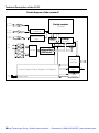
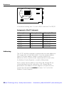
Axis1
IRQ1
I5RQ1
IRQ11
2
IRQ1
IRQ
0
IRQ
9
5
Axis2
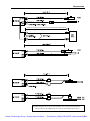
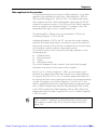
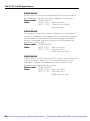
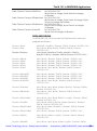
In the above setting, axis 1 is set to IRQ15 and axis 2 to IRQ12.
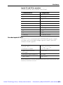
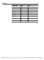
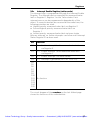
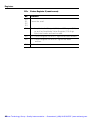
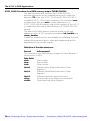
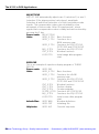
Assignment of the PC interrupts
Interrupt
Interrupt number
Interrupt address
IRQ5
0D
034 to 037
IRQ9
71
1C4 to 1C7
IRQ10
72
1C8 to 1CB
IRQ11
73
1CC to 1CF
IRQ12
74
1D0 to 1D3
IRQ15
77
1D7 to 1DF
Addressing
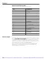
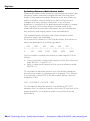
The IK 121 and the computer communicate over port addresses
(I/O range) with a 16-bit data width. Since the vacant address
space in the port address range is severely limited, the
addresses of the counters were superimposed on each other.
An Address Pointer Register is used to differentiate.
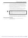
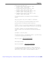
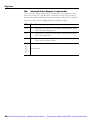
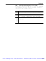
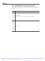
Each counter has five address lines B0 to B4. B0 and B1 are
connected directly to the system bus. B2, B3 and B4 are
generated in the Address Pointer Register. A2 and A3 of the
system bus decode the counters for axes 1 or 2 or for the
Address Pointer Register.
22
Artisan Technology Group - Quality Instrumentation ... Guaranteed | (888) 88-SOURCE | www.artisantg.com