1
Contents
Contents
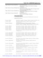
Contents ....................................................................................................................... 2
Items Supplied ............................................................................................................. 6
Versions ..................................................................................... 6
Note on the EMC Guideline 89/336/EWG.................................. 6
Accessories................................................................................ 6
Accessories................................................................................................................... 7
Important Information ................................................................................................ 8
Technical Description of the IK 121............................................................................ 9
Time to access measured values............................................. 11
Hardware .................................................................................................................... 12
PC bus specification................................................................. 12
Encoder inputs IK 121 A .......................................................... 12
Encoder inputs IK 121 V........................................................... 13
Encoder outputs....................................................................... 14
Encoder signal adjustment....................................................... 16
External functions .................................................................... 17
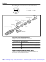
Assembling the connector for the external functions .... 18
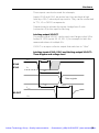
Latching measured values via external inputs................ 18
Latching output X3.OUT................................................. 19
Latching inputs X3.L0, X3.L1 and latching
output X3.OUT: Time diagram and voltage level............ 19
Latching measured values from multiple IK 121s .......... 21
Interrupts ................................................................................. 21
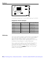
Addressing ............................................................................... 22
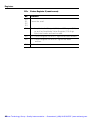
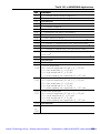
Registers..................................................................................................................... 24
Overview of registers .............................................................. 24
Data registers for the counters ................................................ 25
0Ch: Initializing Register 1 (write mode)......................... 26
0Ch: Initializing Register 2 (write mode)......................... 27
0Eh: Control Register 1 (write mode)............................. 28
0Eh: Status Register 1 (read mode) ............................... 29
0Eh: Status Register 2 (read mode) ............................... 30
10h: Reference Mark Register (write mode).................. 31
10h: Amplitude Value Register (read mode)................... 34
12h: Enable Register for measured value latch
(write mode) ........................................................... 35
12h: Register for axis cascading and for I²C bus control
(write mode) ........................................................... 36
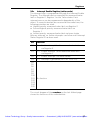
14h: Interrupt Enable Register (write mode) .................. 37
14h: Interrupt Status Register 1 (read mode)................. 38
14h: Interrupt Status Register 2 (read mode)................. 39
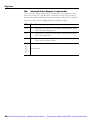
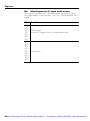
16h: Offset Register for 0° signal (write mode) ............. 40
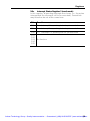
16h: Amplitude for 0°signal (read mode)........................ 41
2Artisan Technology Group - Quality Instrumentation ... Guaranteed | (888) 88-SOURCE | www.artisantg.com