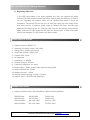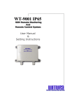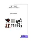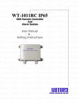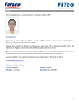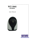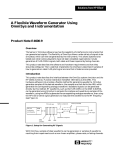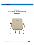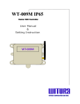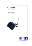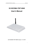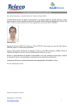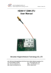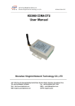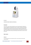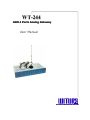
1
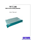
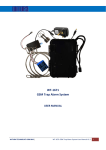
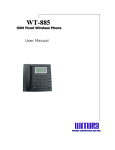
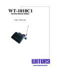
WT-244
G
GS
SM
M4
4P
Po
orrttss A
An
na
allo
og
gG
Ga
atte
ew
wa
ay
y
User Manual
W
R
R
R
W
T
U
A
C
O
P
O
A
T
O
N
S
D
N
B
H
D
WIIIT
TU
UR
RA
AC
CO
OR
RP
PO
OR
RA
AT
TIIIO
ON
NS
SD
DN
NB
BH
HD
D
WT-244 GSM 4 Ports Analog Gateway
GSM Gateway Introduction
Welcome to use our GSM Analog Gateway (also named as Analog Channel Bank/ SIM
Bank) to enter a novel communication world, which absorbs high-tech and delicate
design out of your imagine.
The GSM Analog Gateway enables you to quickly achieve the GSM cell telephone
communication just via simple operations of wired telephone.
This briefing helps you understand the functions of GSM Gateway step by step. Before
using that equipment, please read this briefing in details.
OVERVIEW
•
4 Voice channels are individually connected with 4 ports of GSM brand new industrial
GSM modules
•
Simple Installation “Easy Configuration via DTMF”
•
LED GSM status display
•
GSM Frequency Bands: 900/1800Mhz dual-band, 850/900/1800/1900Mhz quad-band
•
Anti-Polarity Signal (Better reversal) for accurate billing
•
High gain external antenna with 3m cable for optimal signal strength
•
Quick call set up and release/echo cancellation
•
4 SIM per channel
•
Individual Channel power supply for easy card replacement
•
Thunderstorm and lighting protection
WT-244 APPEARANCE VIEW
Front View with Power Switch & Antenna
WT-244 – USER MANUAL – Rev.1 – Technical Support: [email protected]
COPYRIGHT ©2008 WITURA CORPORATION SDN BHD
2
WT-244 GSM 4 Ports Analog Gateway
Rear View with Connection to Telephone & PC
View of 4 SIM Card Holder at the board of 1 Port
ATTENTION!!!
•
Please read the following specific rules
-
•
Against the rules will cause danger or violate the law
Echo off
-
Before using this equipment, please make sure your position has no echo off
function for wireless radio frequency signal
•
Interference
-
The similar to all mobile telephones, it is subject to the interference, which
affects functions of the telephone
•
Explosion district
-
At explosion districts or places signed “close wireless transmitting devices”,
please do not use the equipments
•
Latent explosion environment
-
At environment that there is latent explode possibility, such as gas station,
chemistry products, combustible liquid, air conveyance car or store warehouse
etc., please do not use the equipments.
WT-244 – USER MANUAL – Rev.1 – Technical Support: [email protected]
COPYRIGHT ©2008 WITURA CORPORATION SDN BHD
3
WT-244 GSM 4 Ports Analog Gateway
•
Children
-
Do not let the children play the equipment. Children may be stabbed or hurt
other people with the antenna. Children may damage the interface, or make
telephone calls freely to increase your telephone expenditure.
•
Maintenance
-
Only the qualified technicians can install or maintain the equipments. If the
equipment aborts, please contact the dealer. Do not open the equipments or
maintain them by groups and individuals without authorization to prevent
damaging the equipments.
•
Antenna
-
Only approval antenna can be used, do not link the antenna which do not match
with the equipments. The unqualified antenna in use will damage the equipments.
Antenna must keep vertical and off the telephone, the antenna cable cannot be
bound with telephone line together. Do not touch antenna or approach antenna in
range of 10m during calling.
•
Power
-
•
The equipments regularly use 110-220V AC
Installation and connection
-
Make sure the “Power Switch” on the panel is placed in break (the switch is
placed in the “O” position) when installing the equipments and connecting with
other equipments according to the guidebook. Operating with electricity may
damage the equipments.
•
Configuration
-
After the equipments installed, only after each route of the equipments has been
system
initially
configured
by
dealers
or
network
service
provider,
the
equipments can perform formally. Only dealer or network service provider can
initially configure the equipments system, avoiding the equipments damage due
to the mistake of system configuration.
•
Connecting to other equipments
-
While connecting to other equipments, please read the user guide carefully to
acquire detailed safety guide. Do not connect to the products which do not match
with the equipments.
WT-244 – USER MANUAL – Rev.1 – Technical Support: [email protected]
COPYRIGHT ©2008 WITURA CORPORATION SDN BHD
4
WT-244 GSM 4 Ports Analog Gateway
SUMMARY
The design of the PRI Gateway (Analog Channel Bank) aims to provide a kind of
standard frequency telephone in the area covered by the digital mobile network
The interface of the PRI Gateway (Analog Channel Bank) provides a transparent
connection between the standard telephone and the mobile net, which has the function
of emulation exchange and offers the following function:
•
Dialing tone
•
Dialing a number with DTMF
•
The bell flow signal
•
Versa pole signal
The exterior interface of the PRI Gateway (Analog Channel Bank) has:
•
RJ-11 electric outlets connecting to telephone or fee counter
•
Antenna electric outlets (FME)
•
Pick up or hang up the telephone handset indicator
•
The strong or weak signal indicator
Configuration And Installation
1. The whole pack of the PRI Gateway includes:
•
•
•
•
•
Analog Channel Bank (Main Unit)
High Gain Antenna
Antenna Splitter
110 – 220V AC Power Line
Telephone Cord
1 set
1 pcs
1 pcs
1 pcs
4 pcs
2. Installation Procedure
The equipment provides digital GSM network communication, which required a valid
SIM Card.
a) Put he GSM Analog Channel Bank in pedestal
b) Switch of the power on the behind-panel (switch is kept at “O”)
c) Insert the valid SIM Card
WT-244 – USER MANUAL – Rev.1 – Technical Support: [email protected]
COPYRIGHT ©2008 WITURA CORPORATION SDN BHD
5
WT-244 GSM 4 Ports Analog Gateway
•
Screw off the two fixed screws in the bottom front0panel, and remove the
bottom front-panel
•
Insert the SIM Card in the correct direction (the most right hand route is from
left to the right, others are from right to left)
•
Fix the bottom cover, and tighten the screws
d) Wiring antenna into antenna electric outlet
e) Connect one end of the line with the RJ-11 telephone outlet, and the other end
with the telephone (fee counter)
f) Connect one end of a 85-240V AC power adapter into 110-220V power outlet, the
other end into 220V power outlet on behind-panel
g) Open the power switch on behind-panel (switch is placed in “-” appearance)
After the equipments installed, each route of the equipments has to be initially
systematic configured by dealer or network service provider to assure the formal
operation of equipments.
3. Instruction
a) This PRI Gateway (Analog Channel Bank) application figure:
WT-244 – USER MANUAL – Rev.1 – Technical Support: [email protected]
COPYRIGHT ©2008 WITURA CORPORATION SDN BHD
6
WT-244 GSM 4 Ports Analog Gateway
The installation connecting to charging device
b) The front-panel indicator appearance illumination
There are pick-up or hang-up handset indicator and strong or weak signal
indicator for each route of the PRI Gateway (Analog Channel Bank)
Pick up or hang up the handset: If pick up a route of the PRI Gateway (Analog
Channel Bank), the pick up or hang up indicator keep bright. (Red LED). Strong
or weak signal: Indicating the received signal of each route GSM Analog Channel
Bank. The stronger the signal is, the more the bright lights will show. In the state
of system configuration, four lights flash (Green LED)
WT-244 – USER MANUAL – Rev.1 – Technical Support: [email protected]
COPYRIGHT ©2008 WITURA CORPORATION SDN BHD
7
WT-244 GSM 4 Ports Analog Gateway
c) Make a call
When the “strong or weak signal” indicator indicates there is enough receiving
signal, pick up the telephone which connecting with the PRI Gateway (Analog
Channel Bank), and you can hear the dialing tone immediately; If connecting the
machine with the fee counter, it will show the telephone number you dial. After
the other side picks up the phone handset, the charging machine starts working.
For shortening the network accessing time, it is suggested to press the “#” key
after dialing the telephone number (means to press the “accelerates dial” key).
Without dialing more numbers in 7 seconds after first dial, the first telephone
number will be redialed automatically.
d) Call in
When there is a call in, the telephone rings. Pick up the phone and converse
e) The operation method of the charge machine
Please read the charge machine manual about the detailed operation method
WT-244 – USER MANUAL – Rev.1 – Technical Support: [email protected]
COPYRIGHT ©2008 WITURA CORPORATION SDN BHD
8
WT-244 GSM 4 Ports Analog Gateway
f) Replacing SIM Card
If the SIM Card needs to be often replaced, the user can replace the single
channel SIM Card without influencing others. Please press the RED key in front of
the unit regarding the channel which will be replaced and make it power off
separately. The power LED will be turn off and then open the front upper-cover
and press the key of channel which needs to replace SIM Card, the LED light
aside the SIM Card will go off. Then the SIM Card can be placing, press the key
again, and the LED light aside the SIM Card will shine bright. If other SIM Cards
need to be changed, it is the similar with above steps.
OTHER SPECIFICATIONS
1. Support Protocol: GSM07.10
2. Maximum RF power output: 2W (GSM)
3. Dialing Tone: 450Mhz continuum
4. Busy Tone: 450Hz 0.35S/0.35S
5. Product Shell: Steel
6. RF Parameter
7. K0dulation: -0.3GMSK
8. Channel Interval: 200KHz
9. Frequency difference: ≤0.1ppm
10. Antenna Gain: Inside keeping 3db/ outside keeping 5db
11. Antenna Resistance: 50ohm
12. Standby current: <15mA
13. Average communicating current: <300mA
14. Support 3.0V/ 1.8V SIM Card Adaptively
TECHNOLOGY INDEX
1. Antenna interface level: 900/1800Mhz or 850/900/1800/1900Mhz
GSM 850Mhz:
RX 869-894
TX 824-849
GSM 900Mhz:
RX 925-960
TX 880-915
GSM 1800Mhz:
RX 1805-1880
TX 1710-1785
GSM 1900Mhz:
RX 1930-1960
TX 1850-1910
WT-244 – USER MANUAL – Rev.1 – Technical Support: [email protected]
COPYRIGHT ©2008 WITURA CORPORATION SDN BHD
9
WT-244 GSM 4 Ports Analog Gateway
2. SIM Card: It support 3VG-SIM Card
3. Phone Interface: Supply main and assist double frequency interface (RJ-11 Phone
Interface)
Hanging Voltage: 45V
Picking Off Voltage: 30mA/ 41mA
Dialing Tone Frequency: 450Hz
4. Antenna interface: Antenna Amplifying >4.5DB
5. Adapter Interface;
INPUT: AC 175~260V
OUTPUT: +9V/1000MA
6. Operation Circumstance;
Operation Temperature: -10°C ~ 60°C
Storage Temperature: -20°C ~ 70°C
Operation Humidity: 45% - 95%
Atmosphere pressure: 86 – 106Kpa
Environment noise: <60DB’
Transmitting Power: 2W
Sensitivity: <-104Dbm
Antenna Amplifying: >1.5db
Dialing frequency: 450Hz
Hanging Voltage: 45V
Picking current: 30mA/41mA
Power input: 85-240V
WT-244 – USER MANUAL – Rev.1 – Technical Support: [email protected]
COPYRIGHT ©2008 WITURA CORPORATION SDN BHD
10
WT-244 GSM 4 Ports Analog Gateway
EXCEPTION HANDLES
1. Network
After opening the GSM PRI Gateway (Analog Channel Bank), the equipment needs
about 10 seconds to search for the local network of GSM. When searching the most
right-hand “signal strong or weak” indicator would flash once per second until
searching completes, then the “strong or weak signal” indicator starts indicating to
make a phone call.
2. Power
Connect to power supply and make sure you have opened the “power switch” behind
the GSM PRI Gateway (Analog Channel Bank), (“power switch” is placed in “-”
appearance) and the switch key on the each route inside the equipment. While
turning on the equipment, all indicators on front panel will flash once.
a) Check out the 100-200V AC power line connecting well with an alternate current
electric outlet, and with the AC outlet of the PRI Gateway (Analog Channel Bank)
intact.
b) If the above check can’t expel the breakdown yet, please contact the dealer.
3. Speakerphone
It the speakerphone can’t work normally, please check whether the operation is
correct, and the connecting with GSM Analog channel bank is well. Otherwise, try to
change another telephone to test whether the condition and internal circuits of the
equipment work normally or not. Due to the strong shooting power of the equipment,
it is suggested to use the telephone with anti-electromagnetism interference to
prevent headphone from interference voice.
WT-244 – USER MANUAL – Rev.1 – Technical Support: [email protected]
COPYRIGHT ©2008 WITURA CORPORATION SDN BHD
11
WT-244 GSM 4 Ports Analog Gateway
FEATURES/BENEFITS
•
Plug-And-Play: Simple installation and easy configuration via DTMF
•
Takes only minutes to install and start service
•
Supports 900/1800 dual- band or 850/900/1800/1900Mhz quad-band
•
Signal auto sensing for port hanged prevention
•
Providing Low cost to setup voice directly into the GSM Network over VOIP FXO
termination
•
Block unwanted prefixes
•
High gain external antenna with 3M cable for optional signal strength
•
Quick call set up and release
•
Echo cancellation
•
Accurate called connected reverse polarity signal for billing
•
CLID, PIN, audio set capability
•
Automatic end-of-dialing after 3 seconds (no SEND key)
•
Support Inbound and Outbound Caller ID display
•
Worldwide flexible power supply
•
Add prefixed code automatically
•
Locking wireless terminal
•
Locking SIM Card
•
Locking service provider
•
Locking districts
•
Call billing prefixed
•
Caller ID blocked (optional and need network supported)
•
Voice volume adjustable
•
Providing corporate business fixed to mobile/ mobile to fixed telephony
•
Providing rural connectivity over GSM networks
•
Providing quick basic telephony provisioning
•
Providing GSM connectivity for river boats, coastal cruise ships
•
Providing connectivity to fixed network back-up via GSM
•
Providing VPN connectivity between two corporate businesses with high security
requirements, and many other more applications
WT-244 – USER MANUAL – Rev.1 – Technical Support: [email protected]
COPYRIGHT ©2008 WITURA CORPORATION SDN BHD
12
WT-244 GSM 4 Ports Analog Gateway
DESCRIPTION FOR SETTING
Entering the setting “**2008#” from a DTMF Phone in order to go into the Setting Mode.
When hang-up the phone, it will save and quit from the setting mode.
1. Volume Setting
•
#X#: Adjust the SPK High or Low. X indicate High or Low, X=1-5. 1 is the
Lowest SPK, 5 is the Highest SPK.
Example:
#2# means SPK Volume as 2
#4# means SPK Volume as 4
•
#*X#: Adjust the MIC High or Low. X indicate High or Low, X=1-4. 1 is the
Lowest MIC, 4 is the Highest MIC.
Example:
#2# means MIC Volume as 2
#4# means MIC Volume as 4
2. SIM Card Setting
a)
•
*1X#: Indicate starting to use from SIM Card No. X. X=1-4
Example:
*12# means starting to use from SIM Card No. 2
*14# means starting to use from SIM Card No. 4
b)
•
*2*1XXX#: Indicate Number of times using SIM Card No. 1. XX=001-999
•
*2*2XXX#: Indicate Number of times using SIM Card No. 2. XX=001-999
•
*2*3XXX#: Indicate Number of times using SIM Card No. 3. XX=001-999
•
*2*4XXX#: Indicate Number of times using SIM Card No. 4. XX=001-999
WT-244 – USER MANUAL – Rev.1 – Technical Support: [email protected]
COPYRIGHT ©2008 WITURA CORPORATION SDN BHD
13
WT-244 GSM 4 Ports Analog Gateway
Example:
*2*1008# means the number of times using SIM Card No. 1 is 8 times
*2*3125# means the number of times using SIM Card No. 3 is 125 times
c)
•
*3*1X#: Indicate whether SIM Card No. 1 enable or disable.
X=0 means disable to us, X=1 means able to use
•
*3*2X#: Indicate whether SIM Card No. 2 enable or disable.
•
*3*3X#: Indicate whether SIM Card No. 3 enable or disable.
X=0 means disable to us, X=1 means able to use
X=0 means disable to us, X=1 means able to use
•
*3*4X#: Indicate whether SIM Card No. 4 enable or disable.
X=0 means disable to us, X=1 means able to use
Example:
*3*20# means SIM Card No. 2 is disable
*3*41# means SIM Card No. 4 is enable
Notes:
i.
If the Setting for SIM Card No. X cannot be used, it will automatically skip the
SIM Card No. X when the SIM Card is routing.
ii. Auto switching when the SIM Card is routing.
iii. If only required using ONE SIM Card, it should be setting to disable for the rest
of the 3 SIM Card. At the same time, set this SIM Card to enable, and start to
use from this SIM Card.
iv. If using TWO SIM Card is enable (if the number of times using did not set,
every SIM Card only will use ONE time), system will automatically go into the
routing mode.
v. The default Number of times using every SIM Card is 1
3. Incoming Call Setting
•
*4X#: Setting for Barring Incoming Call. X=0 means Barred Incoming Call.
X=1 means Allowed Incoming Call.
Example:
*40# means Barred Incoming Call
*41# means Allowed Incoming Call
WT-244 – USER MANUAL – Rev.1 – Technical Support: [email protected]
COPYRIGHT ©2008 WITURA CORPORATION SDN BHD
14
WT-244 GSM 4 Ports Analog Gateway
4. Speed Dial Setting
•
*5X#: Indicate the delay time (seconds) for speed dial. X=1-8.
Example:
*52# means auto dial number after 2 seconds dialing destination no.
*55# means auto dial number after 5 seconds dialing destination no.
5. Setting for Factory Default: **000#
•
Default Setting for SPK is 2
•
Default Setting for MIC is 2
•
Default Setting for SIM Card is using SIM Card No. 1
•
Default Setting for Incoming Call is Barred Incoming Call
•
Default Setting for Speed Dial is Delay Time for 3 Seconds
Notes:
a. The default Number of times using every SIM Card is 1.
b. The default for SIM Card No. 2, SIM Card No. 3, SIM Card No. 4 is
disable and only can use SIM Card No. 1. (The system will keep continuing
using SIM Card No. 1)
c. If need to use SIM Card No. 2, it cannot directly do setting for starting using
SIM Card No. 2. It must be first setting to SIM Card No. 2 as Able to use
mode, otherwise it will indicate Error.
DESCRIPTION FOR PANEL INDICATOR
1. Display Indicator: Signal Strength, SIM Card No. X currently in used (Display
Alternatively)
•
L1-L5: Indicate the Signal Strength.
Example:
L1 as Weakest
L5 as Strongest
•
S1-S4: Indicate the SIM Card No. X is currently in used.
WT-244 – USER MANUAL – Rev.1 – Technical Support: [email protected]
COPYRIGHT ©2008 WITURA CORPORATION SDN BHD
15
WT-244 GSM 4 Ports Analog Gateway
Example:
S2 means SIM Card No. 2 is currently in used
Error Indicator:
•
E1: Indicate there is connection problem between the Modules and the PCB
Board (If the display show E1 more than 5 seconds after the terminal switch on)
•
E2: Indicate Cannot Read SIM Card (E2 and SIM X will take turn to display)
•
E3: Indicate Can Read SIM Card but No Signal (E3 and SIM X will take turn
to display)
2. 2 LED Light Indicator. 1 LED for “WORK”, 1 LED for “IN USE”
•
WORK: The LED will lighten up when switch on the terminal. The LED will blink
when the terminal finish register to the Network
•
IN USE: When the terminal is switch on, the LED will lighten up. When the
terminal is switch off, the LED will switch off.
3. One “Reset” button. (Can press “Reset” button when the terminal facing problem)
Notes:
i.
After the setting, please press “Reset” button then only start using.
ii. If the setting is wrong, there is a “du~ … du~” sound
iii. If the setting is successful, there is a “du~…” sound
iv. When the call is successful (start calculating charges), then only consider as
using the SIM for 1 time.
v. If the terminal indicates Error, wait until the Light Indicator for “WORK” blink,
then the terminal will go into “Setting” mode. It cannot call out. If the user try
to call out, it will indicate “du~ … du~” sound
WT-244 – USER MANUAL – Rev.1 – Technical Support: [email protected]
COPYRIGHT ©2008 WITURA CORPORATION SDN BHD
16
WT-244 GSM 4 Ports Analog Gateway
Warranty
Witura Corporation Sdn Bhd guarantees all WT-244 GSM 4 Ports Analog Gateway against
defective parts and workmanship. Witura Corporation Sdn Bhd shall, at its option, repair
or replace the defective equipment upon the return of such equipment to any Witura
branch. This warranty applies ONLY to defects in components and workman-ship and
NOT to damage due to causes beyond the control of Witura, such as incorrect voltage,
lightning damage, mechanical shock, water damage, fire damage, or damage arising out
of abuse and improper application of the equipment.
Note: Wherever possible, return only the PCB to Witura Service Centres. DO NOT
return the enclosure.
The WT-244 is a product of Witura Corporation Sdn Bhd and is manufactured by
Shenzhen Witura Telecommunications Co., Ltd.
WT-244 – USER MANUAL – Rev.1 – Technical Support: [email protected]
COPYRIGHT ©2008 WITURA CORPORATION SDN BHD
17