1
GRUNDFOS INSTRUCTIONS
Installation and operating instructions
2
Introduction
PC Tool CU 300 kit
The PC Tool CU 300 kit you have just opened consists of:
• 1 CD ROM containing PC Tool CU 300 software, these installation and operating instructions and documents mentioned under references.
• 1 Grundfos CU 300 RS-232 cable for a connection of a PC to CU 300.
• 1 Registration card.
• These Installation and operating instructions.
System requirements
The minimum system requirements of the PC Tool CU 300 software are as follows:
• Windows 95/98/NT/ME/2000/XP.
• Pentium 100 MHz or higher.
• 16 Mb of RAM memory.
• 9 Mb of hard disk space.
• Monitor resolution 800 x 600 or higher.
• Mouse or other pointing device.
• RS-232 COM port.
Contents
These Installation and operating instructions cover the following topics:
Topic
References
See Page
Description
4
Installation
6
Getting started
8
The Main window
9
CU 300 operating and status reading
12
CU 300 installation configuration
15
Fault finding
18
For further information, please refer to...
• CU 300 Installation and operating instructions, 96427972 xxxx.
• G100 Installation and operation instructions, 96428779 xxxx.
• PC Tool Link adapter instructions, 96475749 xxxx.
3
Description
Purpose:
PC Tool CU 300 can be used for...
• Configuration of CU 300 and SQE pump (e.g. during installation).
• Interactive operation and monitoring of SQE pump installations with CU 300.
• Troubleshooting CU 300 and SQE pump.
• Demonstration of CU 300 and SQE pump functionality for training or
sales purposes.
• Showing perspectives in CU 300/SQE pump networking and SCADA system
applications.
User interface
PC Tool CU 300 uses a graphics based user interface with active zones (hot spots),
giving the user a visual impression of control actions and the relation between the
data information and the physical pump application.
Possibilities
Via the interactive graphics the user can operate and monitor single CU 300 units or
complete GENIbus networks of up to 32 CU 300 units.
Via a modem or via the Grundfos gateway G100 with radio or modem the PC Tool
CU 300 can operate distant single CU 300 units or large CU 300 networks.
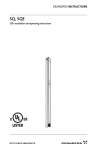
Optional connections
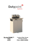
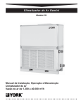
There are three main options for connection of a PC to a CU 300:
1. Using RS-232 for direct connection, see fig. 1, 1a, or connection via modem, see
fig. 1, 1b.
2. Connection to GENIbus via the GRUNDFOS PC Tool Link adapter, see fig. 1, 2.
3. Via G100 port 1 (using the G100 Radio/Modem/PLC version in the following referred to as the R/M/P version), see fig. 1, 3.
The connection to choose depends on your application and your requirements.
2
COM port
COM port
COM port
b)
c)
Modem
Modem
RS-232/RS-485
GRUNDFOS
PC Tool Link
adapter
Direct
a)
b)
Direct
a)
3
Radio
1
G100*
POWER
POWER MNC
POWER GENI
GENI TxD
GENI RxD
FAULT
Genibus
DI
Port 1
DCD
RTS
TxD1
RxD1
TxD2
RxD2
Service
Port 2
Main
Network
Connection
GENIbus
RS-232
CU 300
GENIbus
RS-485
CU 300
CU 300
Max. 32 units
RS-485
CU 300
CU 300
Max. 32 units
Fig . 1 Different connection options.
*) The version shown is an R/M/P version.
The service port can be used on any G100 version for direct and modem connection.
Note: Only connection 1a can be made without extra cables or equipment.
4
TM01 7791 0802
Port 1
Description of all the
connection
possibilities
The table below describes the different connection possibilities shown in fig. 1.
Note: The PC Tool CU 300 kit does not include modems, radios, bus cable, D-sub
connectors or standard RS-485/RS-232 adapters. Nor does Grundfos supply these
parts. Included are only the necessary cable for a direct PC connection to one
CU 300. The pin for connection to the CU 300 TxD terminal is marked black.
Connection
1, b)
Modem
2
GENIbus
3, a)
G100 direct
3, b)
G100 modem
3, c)
G100 radio
Requirements
Direct connection to a single CU 300. Use the
special RS-232 PC cable supplied with the tool
and connect to the CU 300 RS-232 terminals.
For remote communication with single CU 300 installations. Use the CU 300 RS-232 terminals to
connect to a modem according to the wiring specification below.
For connection of up to 32 CU 300 units via
GENIbus. Use the CU 300 RS-485 bus terminals
(A, Y, B) and connect the PC via a GRUNDFOS
PC Tool Link adapter.
Direct connection via G100 to a network of up to
32 CU 300 units. Use the CU 300 RS-485 bus terminals (A, Y, B) to connect CU 300 to G100 according to the wiring specification below.
Modem connection via G100 to a network of up to
32 CU 300 units. Use the CU 300 RS-485 bus terminals (A, Y, B) to connect CU 300 to G100 according to the wiring specification below.
1 Grundfos CU 300 RS-232 cable
(included).
Radio connection via G100 to a network of up to
32 CU 300 units. Use the CU 300 RS-485 bus terminals (A, Y, B) to connect CU 300 to G100 according to the wiring specification below.
1 G100 Radio/Modem/PLC.
2 radios.
2 RS-232 radio cables.
Twisted-pair bus cable with screen.
1 Sub-D, 9-pin connector to G100.
Wiring specification
for the different cable
connections
Cable
connector
1
2
3
4
5
6
7
8
9
9-pin D-sub female.
Pin No.
TM01 1383 0400
1, a)
RS-232
Description
1
2
3
4
5
6
7
8
9
1 CU 300-to-modem cable.
1 standard modem cable.
2 standard modems.
1 PC Tool Link adapter.
Twisted-pair bus cable with screen.
1 G100 Radio/Modem/PLC.
1 standard RS-232 cable.
Twisted-pair bus cable with screen.
1 Sub-D, 9 pin connector to G100.
1 G100 Radio/Modem/PLC.
2 modems.
2 RS-232 modem cables.
Twisted pair bus cable with screen.
1 Sub-D, 9 pin connector to G100.
CU 300 RS-232
CU 300 RS-485
to G100 GENIbus
To PC 1)
To modem
A
B
Y (GND)
-
TxD
RxD
2)
GND
2)
RI
RxD
TxD
DTR 3)
GND
DTR 3)
-
1)
This cable is included in the tool package.
Connect these together in CU 300 terminals.
3) DTR is connected to both pin 4 and pin 7 of the cable connector.
2)
List of products
Product
G100 R/M/P
GRUNDFOS PC Tool Link adapter
Product No.
96 41 11 36
96 47 20 84
5
Installation
Software Installation
Use the following procedure when the PC Tool CU 300 software is installed on a PC:
Step
Action
1
Place the CD ROM in the CD drive.
2
With the Windows Explorer locate the file setup.exe on the CD ROM and
double click it.
3
From here the program will guide you through the installation.
When you have completed the installation, the PC Tool CU 300 program can be run
via the start menu:
Start | Programs | Grundfos PC Tools | PC Tool CU 300.
Hint
CU 300 installation
6
Use the following procedure if you want to make a shortcut PC Tool CU 300 icon on
your desktop:
Step
Action
1
Open the Windows explorer by right-clicking the Start icon and select ‘Explore’.
2
Open the folder:
Windows \ Start Menu \ Programs \ Grundfos PC Tools.
3
Right-click the PC Tool CU 300 menu item and select ‘Create Shortcut’.
4
Right-click the created shortcut and select ‘Rename’.
5
Name it “PC Tool CU 300” and drag the item to the desktop with your
mouse.
No special configuration of CU 300 is needed to use the tool. Just connect the right
cable to the right terminals as described and illustrated in the section Optional connections, page 4. See also the CU 300 Installation and operating instructions. CU
300 automatically detects the presence of communication signals on the serial channels RS-485 or RS-232. Allow up to 40 s for communication to be established after a
power up. If communication is switched from one channel to another, CU 300 must
be powered off and on again. Only one channel can be in use at a time.
If you are not using G100 you can skip to the section Getting started, page 8.
Accessing G100 via the Service Port requires no changes in the hardware configuration. A communication speed of 9600 baud is the factory setting.
If you are using G100 R/M/P Port 1 to communicate with CU 300, this requires the
Port 1 DIP switches on the R/M/P expansion board to be correctly set. You need to
dismantle the front cover. The DIP switch is located at the edge of the circuit board
close to the middle. See also the G100 Installation and operating instructions.
Function
Speed of
Protocol IO type
communication
G100 hardware
configuration
Direct *
Modem
Radio
G100 R/M/P Port 1 DIP switch setting
DIP switch No.
1
2
3
4
5
0
0
1
0
0
1
-
6
-
7
-
8
-
Auto detect *
-
-
0
0
0
-
-
-
1200
2400
4800
9600
baud
baud
baud
baud *
-
-
-
-
-
0
1
0
1
0
0
1
1
0
0
0
0
19200 baud
-
-
-
-
-
0
0
1
* Factory setting
7
Getting started
Locate PC Tool CU 300 in Start | Programs | Grundfos PC Tools and start it. The
screen you will see depends on the tool setup chosen the last time the tool was
started. If you have just installed the tool it has the Standard Tool Setup. This will
work right away if you are using COM 1 port of your PC and your network connection
is a direct RS-232 connection (fig. 1, 1a)). In this case a screen image as shown in
fig. 3 will result (the number of CU 300 icons may differ from your system), and you
can skip to section The Main window.
If your Operation window wrongly shows no CU 300 icons it is likely that the setup of
your tool does not match your physical connection (e.g. the COM port or network
connection).
Note: In some situations it may take a while (up to 40 seconds) for the tool to establish communication.
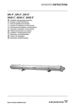
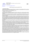
Check the setup by opening the window File | General Tool Setup. Select the correct connection in the ‘Connection type’ pull-down menu and configure it in the corresponding configuration tab. If you are using modem or G100 with modem, fill in the
modem initialisation string: ATS0=1.
Digital Input can be shown either in metric units or US units, use the check box
'Show Digital input in US units' to select the preferred units. The check boxes 'Graphic interface' and 'Show hot spots' can be used to change the appearance of the
user interface.
Finally click the [OK] button to save your tool setup to the hard disk. For all connection types, except those using a modem, communication will now be attempted and
after a few seconds the icons of the connected units should appear. Consult section
Fault finding if it does not work. If your network connection is a modem or G100 with
modem, use Dial up from the Menu Bar to add phone numbers to the phone book or
to make a call to the CU 300 site.
TM01 8502 2702
General Tool Setup
Fig. 2 General Tool Setup window with the standard tool setup
8
The Main window
Introduction
We now assume that your network connection works and you are ready to take a
short tour of your screen to get an explanation of what you see and what you can do.
The things explained are independent of the kind of network connection you use you can even go through this tour if you have not connected anything to the PC.
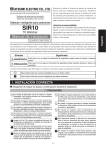
Description
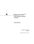
The background picture is a borehole with an SQE pump, pipes, power cables and a
CU 300 unit.
The picture is interactive, and the animated water flow in the picture will give you a
visual feedback of the system response to your control actions. Clicking on the objects marked with arrows will open windows showing status values from the system
or give you control buttons to operate the system. Interactive objects or zones in the
picture are called Hot Spots. When you position the mouse pointer on top of one of
them a yellow Hint Label will explain what the Hot Spot can be used for.
The Operation window is always opened automatically when the tool is started. It
shows you an overview of the network connected to your PC with the connected
units displayed as small icons. This is called the Network List.
TM01 8503 0802
The Operation window below shows a situation where the ‘Connection type’ is
‘GENIbus/RS-232’ and there are two CU 300 units connected.
The drawing of the Network List in the Operation window will show the CU 300 icons
connected via a G100 icon if ‘Connection type’ G100 has been selected.
Fig. 3 Screen image example when starting the tool with the Standard Tool Setup and a connection to GENIbus. In this example two CU 300 units are connected to GENIbus
Further information
If more than one CU 300 unit is connected, which is possible using GENIbus or
G100, the tool automatically picks one of them to be the Active Unit. The Active Unit
is the one you interact with. You change to another unit by clicking on its icon.
At the top of the tool screen you see the Menu Bar. This bar has drop down menus
which give you access to all tool windows. An overview of the complete Menu Bar
contents can be seen in section Overview of tool menus, page 11.
At the bottom of the tool screen, just above the Windows Task Bar is the Status Bar.
This bar shows miscellaneous status information of the tool itself and the network
connection. This can often give a hint to the solution of problems if the tool is not acting as expected.
9
Having established your connection and having familiarised yourself with the main
screen you are now ready to learn how to customise the tool graphics to fit your physical application.
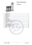
Open File | Graphic Tool Setup. From this window you can select between a series
of standard applications described in the following table and of communication devices. Fig. 4 shows an example where ’Filling a tank from well using level control’ has
been chosen as application and ‘Communication device’ is 'modem'.
Note: This setup is exclusively visual. It does not change anything in the way the tool
works, the way CU 300 works, the way sensors are scaled etc. It is therefore possible to misfit the screen appearance to the real system behaviour (e.g. in fig. 4 a modem is shown connected to CU 300, but in the Status Bar we see that the real
connection is GENIbus). If no standard application fits the real installation the three
sensors can be set up individually (Customer specific application). All options from
the Graphic Tool Setup window can be seen in the table, page 11.
TM018504 0802
Graphic Tool Setup
Fig. 4 The window File | Graphic Tool Setup for customising the graphics to the use of external sensors
10
Options in the Graphic
Tool Setup window
Options in the ‘Graphic Tool Setup’ window
Communication
device
Standard application
•
•
•
•
•
•
None
Custom specific
Constant-pressure control
Filling a tank using level control
Filling a tank from well using level control
Irrigation
• None
• Modem
• G100
Fig. 5
•
•
•
•
•
None
Pressure tank
Storage tank
Water level
Top of well (pressure)
Digital Input
• None
• Top of well
(flow)
• Start/stop
switch
• Pipeline (flow)
All information in the tool is available via the Menu Bar. The figure below provides an
overview of the complete menu system in PC Tool CU 300.
File
Operation
Print
Load Configuration
Save Configuration
General Tool Setup
General Tool Setup
Exit
Sensor 1 / Sensor 2
• Top of well (flow)
• External setpoint
• Sampling at variable speed
• Maintaining a constant water table
• System with 3 sensors connected
Overview of tool
menus
Customer specific application
Operation
Print
Print to file
Print from file
Status
Installation
Alarm Log.
Unit Info.
CU300 Panel
CU3 Status
SQE Status
Sensor 1+)
Sensor 2+)
Digital Input+)
General Conf.
Sensor Conf.
Alarm Callback Conf.
Dialup*)
Dialup
Hangup
Help
Phone book
No. 1
No. 2
:
Help
Readme.txt
References
About
The tool menus
*) This menu column is only present if the Connection type is ‘Modem’ or ‘G100 with modem’.
+) This menu item is dimmed if the corresponding sensor has not been selected in
File | Graphic Tool Setup.
11
CU 300 operation and status reading
Introduction
In this section we will take a tour of the interactive background.
All status windows from the interactive background continuously refreshes their content, making it possible to dynamically follow changes in values.
The Operation window You open this window by clicking on the on/off button of the CU 300 in the picture or
by selecting Operation | Operation from the Menu Bar. This window is always opened automatically when the tool is started, see fig. 3.
Using the command buttons [Normal], [Stop], [Min] and [Max] in this window you
can manually change the mode of operation of the pump. It has the same result as
using the equivalent commands from R100.
Using the [Reset] button you can manually acknowledge alarms and make the CU
300 attempt a restart of the pump. It has the same result as acknowledging an alarm
by pressing the on/off button on the CU 300 or using the Reset command from R100.
The setpoint can be adjusted with the up/down arrow or by pulling the slider with the
mouse. The setpoint is a speed setpoint, measured in rpm, if CU 300 operates in
Control mode ‘Open loop’. If CU 300 operates in Control mode ‘Closed loop’, the setpoint is measured in the same unit as sensor 1.
In the Network List, use the mouse to select which CU 300 you communicate with by
clicking on its icon. Once selected, all data you see in the different windows belong
to this CU 300. Selecting a new CU 300 will make all status windows which are opened refresh their content with data from the new unit in a few seconds, and all installation windows will close automatically.
If a CU 300 has an alarm, this will be shown with a red frame around the CU 300
icon. The cause of the alarm condition can be found in the CU 300 Status window
(see The CU 300 Status window, page 13).
The SQE Status
window
Data Item
Open this window by clicking on the submersed SQE pump in the picture or by selecting Status | SQE Status from the Menu Bar. Below is a table describing all the Data
Items which are displayed in this window. Like all status windows the values are continuously updated.
Description
Range
Speed
Temperature
Power input
Power consumption
Speed of the pump
Temperature of the SQE power electronics
Power
Energy
[7000; 10700 rpm]
[–16; 138 °C]
[0; 2500 W]
[0; 130,000 kWh]
Operating hours
No. of starts (power up)
No. of starts (start/stop)
No. of hours the pump has been running
No. of times the pump has been powered up
No. of times the pump has been stopped
and started
130558 h
16,650,000
16,650,000
*) Percentage specifications are related to full range unless otherwise stated.
12
Accuracy *)
1%
5°C
5%
5% of the
actual value
+/- 2h
+/- 1
+/- 1
The CU 300 Status
window
Data Item
Operating Mode
From
Setpoint
Open this window by clicking in the bottom area of the CU 300 in the picture or by selecting Status | CU 300 Status from the Menu Bar. Below is a table describing all
the data items which are displayed in this window. Like all status windows the values
are continuously updated.
Description
Actual setpoint
Mode of operation
Source of operating mode
Commanded Setpoint (GENIbus or
R100)
Setpoint attenuation from external
analogue input
Resulting actual setpoint
Alarm
Warning
Actual alarm
Actual warning
External setpoint
Range
Accuracy *)
Normal, Stop, Min., Max.
GENIbus, GENIlink, sensor
Open loop: [7000; 10700 rpm]
Closed loop: [sensor range]
[0; 100%]
0.5%
Open loop: [7000; 10700 rpm]
Closed loop: [sensor range]
-
1%
0.5%
-
*) Percentage specifications are related to full range unless otherwise stated.
The sensor windows are only active if the corresponding sensor has been selected in
File | Graphic Tool Setup. The active sensors are marked with a yellow Hot Spot arrow and the sensor windows can be opened by clicking on the arrow or via the Status
Menu in the Menu Bar.
The sensor value is scaled according to the sensor configuration in the window
Installation | Sensor Configuration.
If ‘Signal type’ is chosen to be 'No sensor' for the sensor in question (digital sensor
chosen to be 'off') then a dash '-' is shown in the corresponding sensor window.
The accuracy of a sensor input is +/- 2 %.
The CU 300 Panel
window
You open this window by clicking on the upper left corner of the CU 300 or by selecting Status | CU 300 Panel from the Menu Bar. The window shows the CU 300 panel
with text and status diodes. The state of the diodes is an image of their actual state
(off/on/flashing) on the real CU 300.
TM01 8506 0802
The sensor windows
Fig. 6 The CU 300 Panel window
13
You can only open this window by selecting Status | Alarm Log from the Menu Bar.
All alarms are divided in two categories, those related to the SQE pump and those
related to the CU 300 unit. The total number of occurred alarms for the different
alarm types in each category is recorded.
Below the total alarm number is an alarm log of the 5 last occurred alarms from each
category shown with a time stamp. When a new alarm different from the latest alarm
arrives to this alarm log it will push all the previous alarms one position down. Logged alarm No. 5 will be pushed out.
Clicking on the [Details] button for an alarm will give an explanation to the alarm, its
possible cause and remedy.
The Alarm Log cannot be cleared.
TM01 8507 0300
The Alarm Log
window
Fig. 7 The Alarm Log window
Open this window by selecting Status | CU 300 Unit Information, or by double clicking on the selected CU 300 icon in the Operation window Network List. In the ’Information’ field, a series of text strings which are read from the CU 300, and which
describe the unit, will be displayed. In the ’User defined information’ field, the operator can name each installation (‘Name’ field) and make a short description of it
(‘Comments’ field). Both texts will be saved in the PC and tagged to the No. of the
selected CU 300.
The text written in the 'Name' field will be added to the icon text in the Operation window Network List.
TM01 8508 0300
The CU 300 Unit
Information window
Fig. 8 The CU 300 Unit Information window
14
CU 300 installation configuration
Introduction
The configuration windows are updated with the actual values from the selected CU
300 the moment they are opened. Contrary to Status windows, open configuration
windows are not updated dynamically as this would prevent the user from keying in
new configuration values. If another unit is selected from the Operation window Network List while a configuration window is open, this configuration window will be closed. Common to all three configuration windows are also the [Program] button in the
lower right-hand corner. Pressing it will start programming the selected CU 300 with
the values in the window. During this process a progress bar will be shown on the
screen, and if no warning shows up, the programming will be completed successfully.
The General
Configuration window
Open this window by selecting Installation | General Configuration from the Menu
Bar. Below is a table of all the configuration parameters which can be programmed
via this window. All these parameters can also be read or programmed via R100.
Configuration
parameter
Miscellaneous
Control mode
Value range
Open Loop,
Closed loop
Buttons on CU 300
Active, Not active
Dry-running stop
Enable, Disable
[0; 2461 W]
[0; 65/85°C]
Warning temperature
Start delay
Maximum speed
Number
Standby
Auto restart
Repeated standby
time doubling
Dewatering
Dewater
Max. Run Time
Max. Stop Time
[0; 60 s]
[7000; 10700 rpm]
[1; 64]
Enable, Disable
[0:00; 4:00] h:min
Enable, Disable
Factory
setting
Description
Open loop
Open loop: Setpoint is the pump speed.
Closed loop: CU 300 closed loop control tries to
bring the feedback (sensor 1) in accordance with
the setpoint.
Active
The on/off button on CU 300 can be active or not
active.
Enable
The dry-run protection uses a minimum power li0W
mit to detect dry-runing.
If temperature in power electronics exceeds this
temperature the alarm relay will be activated.
0s
Delay from SQE is powered on until it starts.
10700 rpm Upper speed limit.
GENIbus No. as programmed with R100.
0:05 h:min Automatic restart after an alarm stop. The alarm
standby time can be programmed.
Disable
Alarm standby time is doubled after every 10
alarm stops until 4:00 is reached. Will be reset
after 10 h without alarms.
Enable, Disable
Disable
[1; 60 min]
[1; 60 min]
60 min
60 min
Enables or disables the CU 300 dewatering function which is based on the dry-running detection.
Run time according to the Run/Stop diagram.
Current or voltage offset in the sensor signal (e.g.
4-20 mA).
15
The Sensor
Configuration window
Configuration
parameter
Sensor 1
Signal type
Unit
Max. sensor value
Min. sensor value
Limits
Max. stop
Max. warning
Max. alarm
Min. stop
Min. warning
Min. alarm
Stop type
Sensor 2
External setpoint
Signal type
Unit
Max. sensor value
Min. sensor value
Limits
Max. stop
Max. warning
Max. alarm
Min. stop
Min. warning
Min. alarm
Stop type
Digital input
Function
Flow
Accumulated flow
Sensor
Max. Run Time
16
Open this window by selecting Installation | Sensor Configuration from the Menu
Bar. The following table shows all the configuration parameters which can be programmed via this window. All these parameters can also be read or programmed via
R100
Value range
No sensor,
0-20 mA, 4-20 mA,
0-10 V, 2-10 V
m, m³/h, feet, gpm,
%
[1; 250]
[0; 249]
Enable, Disable
[Min sensor value;
Max sensor value]
Fill, Empty
Enable, Disable
No sensor,
0-20 mA, 4-20 mA,
0-10 V, 2-10 V,
SPP 1
m, m³/h, feet, gpm,
%
[1; 250]
[0; 249]
Enable, Disable
[Min sensor value;
Max sensor value]
Factory
setting
No
sensor
Type of electrical signal from sensor.
m
Unit of sensor value.
1
0
Sensor maximum value.
Sensor minimum value (offset from zero).
Max.
Min.
Max.
Min.
Max.
Min.
Fill
Disable
No
sensor
Sensor maximum (high) limit for start/stop control.
Sensor maximum (high) limit for warning.
Sensor maximum (high) limit for alarm, pump will be
stopped.
Sensor minimum (low) limit for start/stop control.
Sensor minimum (low) limit for warning.
Sensor minimum (low) limit for alarm, pump will be
stopped.
Fill: pump stops at high limit and starts at low limit
Empty: pump starts at high limit and stops at low limit
Sensor signal used as external analogue setpoint.
Type of electrical signal from sensor.
m
Unit of sensor value.
1
0
Sensor maximum value.
Sensor minimum value (offset from zero).
Max.
Min.
Max.
Min.
Max.
Min.
Fill, Empty
Fill
Off, Stop, Start,
Flow
[0; 100 l/pulse],
[0;26,4 Gal/pulse]
Off
None, Sensor 1,
Sensor 2, Digital
Enable, Disable
[0; 1000 m³],
[0;264200 gallons]
Description
Sensor maximum (high) limit for start/stop control.
Sensor maximum (high) limit for warning.
Sensor maximum (high) limit for alarm, pump will be
stopped.
Sensor minimum (low) limit for start/stop control.
Sensor minimum (low) limit for warning.
Sensor minimum (low) limit for alarm, pump will be
stopped.
Fill: Pump stops at high limit and starts at low limit.
Empty: Pump starts at high limit and stops at low limit.
Function of the external digital input.
0 l/pulse Scaling digital input for flow measurement.
None
Disable
0 m³.
Signal source for calculation of accumulated flow
(pumped volume).
Stop of pump when defined volume is pumped.
The Alarm Call-back
Configuration window
Open this window by selecting Installation | Alarm Call-back Configuration from
the Menu Bar. Below is a table of all the configuration parameters which can be programmed via this window. None of these parameters can be read or programmed via
R100 or via G100.
Call-back on alarm
Phone
numbers
Call-back
Configuration
parameter
Value range
Factory
setting
Call-back enabled
Enable, Disable
Disable
No. of alarms before call-back
First phone No.
[1; 10]
Second phone
No.
No contact
Overvoltage
Undervoltage
Dryrunning
Overtemperature
Overload
Sensor alarm
Phone No.
Voice *), Data
Phone No.
Voice *), Data
Enable, Disable
10
Data
Data
Disable
Description
Enables the call-back function upon alarms. A
modem must be connected.
CU 300 will make a call-back when this number of alarms has occurred in 24 hours.
e.g. 004586684444w5942
It is possible to individually enable/disable the
call-back function for each alarm.
*) Requires a voice modem connected to CU 300
From the menu item File | Load Configuration it is possible to load a complete configuration from a file and program this configuration to a CU 300. In this way it is very
easy to program many CU 300 units with exactly the same set of parameters.
File | Load Configuration will display the Windows ’Open’ dialogue box prompting
you to select a file.
The default catalogue is C:\program files\Grundfos\PC Tool CU 300\data and all
files of type *.cnf will be displayed. The file factory.cnf, which is installed in this catalogue contains the CU 300 factory configuration. You can select it or any other *.cnf
file and click [Open]. The Load Configuration window below will be displayed.
TM01 8509 0300
Loading and saving a
configuration
Fig. 9 The File I Load Configuration window
In the ‘Comments’ field a text explains details of the selected file (if such information
was saved with the file). With the check boxes, different parts of the configuration file
can be selected. These parts are equal to the contents of settings from the Operation
window and the three configuration windows.
Select the parts you would like to program and click [Program].
You can also do the opposite, save the configuration of a CU 300 unit to a file. You
connect the tool to the CU 300 and select it in the Operation window Network List (if
it is the only unit connected, the tool will select it automatically). Then click File |
Save Configuration which will open the Save Configuration window. You are invited
to write a comment. Then click [Save] and the Windows 'Save As' dialogue box will
be prompting you to select a catalogue and a filename for saving the configuration.
17
Fault finding
Communication with a Fig. 10 shows the situation where PC Tool CU 300 communicates with a CU 300 unit
CU 300 via RS-232
via its RS-232 connection.
directly
If you do not see the correct image of your network in the Operation window i.e. one
CU 300, then go through the following check table.
PC connection
CU 300
Setup of PC tool
Windows system setting
RS-232 connection
TM01 7792 4799
•
•
Fig. 10 PC connected directly to CU 300 RS-232 terminals. The arrows indicate typical
causes of communication problems
Check table for RS-232 connection
CU 300
RS-232 connection
PC connection
PC tool setup
Windows
18
Be sure that the CU 300 unit is switched on
• The cable wires must be connected to the right terminals
on the CU 300 unit.The TxD connection on the included
CU 300 RS-232 cable is marked black.
• Check for short circuits at the connections.
• Check that the cable is not damaged and that cable connections (if any) are sound.
• Check that the cable has been made according to the description, see Wiring specification for the different cable
connections, page 5.
At the back of the PC check to which COM port you have
connected the adapter, and that it is properly fixed.
In File | General Tool Setup check that you are using GENIbus/RS-232 ‘Connection type’ and the right COM port.
• Check in Windows system setting that your COM port is
not disabled or configured to a special use.
• Check that there is not another active program on the PC
using the same COM port.
Communication with a Fig. 11 shows the situation where PC Tool CU 300 communicates with a CU 300 unit
CU 300 via modem
via a modem.
If you do not see the correct image of your network in the Operation window, i.e. one
CU 300 unit, then go through the following check table.
RS-232 connection
PC connection
Modem
Modem
CU 300
•
•
TM01 7793 4799
Modem initialisation
Setup of PC tool
Windows system setting
Fig. 11 PC connected to CU 300 RS-232 terminals via a modem. The arrows indicate typical causes of communication problems.
Check table for modem connection
CU 300
RS-232 Connection
PC Connection
Modem
PC Tool Setup
Windows
Be sure that the CU 300 unit is switched on.
• The cable wires must be connected to the right terminals
on the CU 300 unit.
• Check for short circuits at the connections.
• Check that the cable is not damaged and that cable connections (if any) are sound.
• Check that the cable has been made according to the description, see Wiring specification for the different cable
connections, page 5.
Check the modem are connected to the pc correctly.
• Be sure that the modems are switched on.
• Check to see if the modem line works proberly.
In File | General Tool Setup check that you are using
modem ‘Connection type’ and the right modem from the list.
• Check in Windows system setting that your COM port is
not disabled or configured to a special use.
• Be sure that the right driver for the modem is installed.
A standard Windows driver will not work.
• Check that there is not another active program on the PC
using the same COM port.
19
Communication with a Fig. 12 shows the situation where PC Tool CU 300 communicates with a GENIbus
CU 300 Network via
network consisting of two CU 300 units. It might be that your application is different.
GENIbus
However the procedure in checking the system is general.
RS-232/RS-485
GRUNDFOS PC Tool
Link adapter
Bus cable
CU 300
•
Setup of PC tool
•
Windows system setting
GENIbus
connection
CU 300
Unique address
TM01 7794 0902
PC connection
Fig. 12 GENIbus network example. The arrows indicate typical causes of communication
problems.
If you do not see the correct image of your network in the Operation window - one or
more units might be missing, units appear and disappear or you might not see any
units at all - then go through the following checks.
Check table for GENIbus connection
CU 300
GENIbus connection
RS-232/RS-485
GRUNDFOS PC
Tool Link adapter
PC Connection
PC Tool Setup
Windows
20
• Be sure that the CU 300 units are all switched on.
• Be sure that each CU 300 unit has a unique address (e.g.
number programmed with R100 or with the tool).
• The bus cable must be connected to the right terminals on
the CU 300 unit. The signal wires to A and B and the
screen to Y. Check that the connection to A and B are not
reversed.
• Check for short circuits at the connections.
• Check that the cable is not damaged and that cable connections (if any) are sound. Try to make ohmic measurements.
Study the PC Tool Link instructions.
• At the back of the PC, check to which COM port you have
connected the adapter to and that it is properly fixed.
• In File | General Tool Setup check that you are using
GENIbus/RS-232 ‘Connection type’ and the right COM
port.
• Check in Windows system setting that the COM port you
use is not disabled or configured to a special use.
• Check that there is not another active program on the PC
using the same COM port.
Communication with a The table below describes some of the most common problems when trying to estabCU 300 network via
lish communication between PC Tool CU 300 and the gateway G100. Parts of this
G100
fault finding procedure will make use of PC Tool G100.
Connection to G100
Connection
to service
port
Fault indication
Cause and remedy
Direct
access
G100 icon is red, and the
Status Bar reads: ’Error’.
No communication between PC and G100.
Check that...
• the cable is correct (standard 0-modem cable),
• you are using the correct COM port in your PC,
• the baud rate selection in the PC tool is 9600.
Access
via
modem
Modem connection cannot
be established.
G100 modem is not properly connected to telephone line, or G100
modem is not in auto answer mode.
• Check that the cable between G100 and modem is correct
(standard modem cable = all pins straight through).
• To activate auto answer mode, use a terminal program (e.g. Procomm) to send the following AT-command: "AT&D0".
No communication between PC and G100. This could be due to a bad
Modem connection has
telephone line.
been established but the
G100 icon turns red and the • Hang up and try again.
Status Bar reads: 'Error'.
If this does not help, check that...
• the cable between G100 and modem is correct (standard modem cable = all pins straight through),
• the modem can work without DTR being present. Use a terminal
program (e.g. Procomm) to send the following AT-command:
"AT&D0".
Connection
to R/M/P
version,
port 1
Direct
access
G100 icon is red, and the
Status Bar reads: 'Error'.
No communication between PC and G100. Check that...
• the cable is correct (standard 0-modem cable),
• you are using the correct COM port in your PC, in the window
File | Tool Setup | General Setup
• the baud rate selected in the window File | Tool Setup | General Setup matches the hardware selection on the Radio/Modem/
PLC board,
• the I/O type on the Radio/Modem/PLC board is set to 'Direct'.
Access
via
modem
Modem connection cannot
be established.
G100 modem is not properly connected to the telephone line, or G100
modem is not in auto answer mode.
• Check that the cable between G100 and modem is correct.
Standard modem cable = all pins straight through).
If the I/O type on R/M/P board is set to 'Modem', G100 itself is able to
initialise the modem. The initialisation string can be set up from PC
Tool G100 in the following way:
• Connect the PC to G100 Service port and start PC Tool G100.
• Click the G100 icon.
• Select the [R/M/P board...] button.
• Select the [Alarm setup...] button.
• In the Modem initialisation field write: ‘ATS0=1’.
• Close the menu with [OK].
• Confirm writing data to G100 with [Yes].
• Exit PC Tool G100 and switch off/on G100 to initialise modem.
Modem connection has
been established but after a
while the G100 icon turns
red and the Status Bar
shows: 'Error'
No communication between PC and G100. This could be due to a bad
telephone line.
Hang up and try again.
NOTE: After 8 hours, G100 will by itself terminate a modem communication.
Access The G100 icon is red and
No communication between PC and G100. Check that...
via radio the Status Bar reads: 'Error' • the cable is correct (consult your radio user manual and G100
Product Information to match the pin connections)
• you are using the correct COM port in your PC and
• the baud rate selected in the PC tool matches the dip switch selection on R/M/P board and
• the I/O type on R/M/P board is set to 'Radio' ('Direct' if your radio operates in transparent mode).
(Table to be continued on the next page)
21
(Table continued)
Connection to G100
Connection
to service
port
Fault indication
Cause and remedy
Direct
access
G100 icon is red, and the
Status Bar reads: ’Error’.
No communication between PC and G100.
Check that...
• the cable is correct (standard 0-modem cable),
• you are using the correct COM port in your PC,
the baud rate selection in the PC tool is 9600.
Access
via
modem
Modem connection cannot
be established.
G100 modem is not properly connected to the telephone line, or G100
modem is not in auto answer mode.
• Check that the cable between G100 and modem is correct
(standard modem cable = all pins straight through).
• To activate auto answer mode, use a terminal program (e.g. procomm) to send the following AT-command: ‘ATSO=1’.
No communication between PC and G100. This could be due to a bad
Modem connection has
telephone line.
been established but the
G100 icon turns red and the • Hang up and try again.
Status Bar reads: 'Error'.
If this does not help, check that...
• the modem can work without DTR being present. Use a terminal
program (e.g. Procomm) to send the following AT-command:
‘AT&D0’.
Common to all
connections
The communication between PC tool and G100
seems to be OK. Several
CU 300 units are connected to G100, but none
or only some are shown in
the PC tool.
No communication is taking place between G100 and the CU 300
units.
• Check that the connection between G100 GENIbus port and
GENIbus is correct (see G100 Installation and operating instructions).
• Go through the checks of bus units, GENIbus connections and
GENIbus cable as described in preceding section.
Subject to alterations.
22
Denmark
GRUNDFOS DK A/S
Poul Due Jensens Vej 7A
DK-8850 Bjerringbro
Tlf.: +45-87 50 50 50
Telefax: +45-87 50 51 51
Argentina
Bombas GRUNDFOS de Argentina S.A.
Ruta Panamericana km. 37.500 Lote 34A
1619 - Garin
Pcia. de Buenos Aires
Phone: +54-3327 414 444
Telefax: +54-3327 411 111
Australia
GRUNDFOS Pumps Pty. Ltd.
P.O. Box 2040
Regency Park
South Australia 5942
Phone: +61-8-8461-4611
Telefax: +61-8-8340 0155
Austria
GRUNDFOS Pumpen Vertrieb Ges.m.b.H.
Grundfosstraße 2
A-5082 Grödig/Salzburg
Tel.: +43-6246-883-0
Telefax: +43-6246-883-30
Belgium
N.V. GRUNDFOS Bellux S.A.
Boomsesteenweg 81-83
B-2630 Aartselaar
Tél.: +32-3-870 7300
Télécopie: +32-3-870 7301
Brazil
GRUNDFOS do Brasil Ltda.
Rua Tomazina 106
CEP 83325 - 040
Pinhais - PR
Phone: +55-41 668 3555
Telefax: +55-41 668 3554
Canada
GRUNDFOS Canada Inc.
2941 Brighton Road
Oakville, Ontario
L6H 6C9
Phone: +1-905 829 9533
Telefax: +1-905 829 9512
China
GRUNDFOS Pumps (Shanghai) Co. Ltd.
22 Floor, Xin Hua Lian Building
755-775 Huai Hai Rd, (M)
Shanghai 200020
PRC
Phone: +86-512-67 61 11 80
Telefax: +86-512-67 61 81 67
Czech Republic
GRUNDFOS s.r.o.
Cajkovského 21
779 00 Olomouc
Phone: +420-68-5716 111
Telefax: +420-68-543 8908
Finland
OY GRUNDFOS Pumput AB
Mestarintie 11
Piispankylä
FIN-01730 Vantaa (Helsinki)
Phone: +358-9 878 9150
Telefax: +358-9 878 91550
France
Pompes GRUNDFOS Distribution S.A.
Parc d’Activités de Chesnes
57, rue de Malacombe
F-38290 St. Quentin Fallavier (Lyon)
Tél.: +33-4 74 82 15 15
Télécopie: +33-4 74 94 10 51
Germany
GRUNDFOS GMBH
Schlüterstr. 33
40699 Erkrath
Tel.: +49-(0) 211 929 69-0
Telefax: +49-(0) 211 929 69-3799
e-mail: [email protected]
Service in Deutschland:
e-mail: [email protected]
Greece
GRUNDFOS Hellas A.E.B.E.
20th km. Athinon-Markopoulou Av.
P.O. Box 71
GR-19002 Peania
Phone: +30-10-66 83 400
Telefax: +30-10-66 46 273
Hong Kong
GRUNDFOS Pumps (Hong Kong) Ltd.
Unit 1, Ground floor
Siu Wai Industrial Centre
29-33 Wing Hong Street &
68 King Lam Street, Cheung Sha Wan
Kowloon
Phone: +852-27861706/27861741
Telefax: +852-27858664
Hungary
GRUNDFOS Hungária Kft.
Park u. 8
H-2045 Törökbalint,
Phone: +36-34 520 100
Telefax: +36-34 520 200
India
GRUNDFOS Pumps India Private Limited
Flat A, Ground Floor
61/62 Chamiers Aptmt
Chamiers Road
Chennai 600 028
Phone: +91-44 432 3487
Telefax: +91-44 432 3489
Indonesia
PT GRUNDFOS Pompa
Jl. Rawa Sumur III, Blok III / CC-1
Kawasan Industri, Pulogadung
Jakarta 13930
Phone: +62-21-460 6909
Telefax: +62-21-460 6910/460 6901
Ireland
GRUNDFOS (Ireland) Ltd.
Unit 34, Stillorgan Industrial Park
Blackrock
County Dublin
Phone: +353-1-2954926
Telefax: +353-1-2954739
Italy
GRUNDFOS Pompe Italia S.r.l.
Via Gran Sasso 4
I-20060 Truccazzano (Milano)
Tel.: +39-02-95838112/95838212
Telefax: +39-02-95309290/95838461
Japan
GRUNDFOS Pumps K.K.
1-2-3, Shin Miyakoda
Hamamatsu City
Shizuoka pref. 431-21
Phone: +81-53-428 4760
Telefax: +81-53-484 1014
Korea
GRUNDFOS Pumps Korea Ltd.
2nd Fl., Dong Shin Building
994-3 Daechi-dong, Kangnam-Ku
Seoul 135-280
Phone: +82-2-5317 600
Telefax: +82-2-5633 725
Malaysia
GRUNDFOS Pumps Sdn. Bhd.
7 Jalan Peguam U1/25
Glenmarie Industrial Park
40150 Shah Alam
Selangor
Phone: +60-3-5569 2922
Telefax: +60-3-5569 2866
Mexico
Bombas GRUNDFOS de Mexico S.A. de C.V.
Boulevard TLC No. 15
Parque Industrial Stiva Aeropuerto
Apodaca, N.L. 66600
Mexico
Phone: +52-81-8144 4000
Telefax: +52-81-8144 4010
Poland
GRUNDFOS Pompy Sp. z o.o.
ul. Klonowa 23
Baranowo k. Poznania
PL-62-081 Przezmierowo
Phone: +48-61-650 13 00
Telefax: +48-61-650 13 50
Portugal
Bombas GRUNDFOS Portugal, S.A.
Rua Calvet de Magalhães, 241
Apartado 1079
P-2780 Paço de Arcos
Tel.: +351-21-440 76 00
Telefax: +351-21-440 76 90
Russia
OOO GRUNDFOS
Shkolnaya, ul., 39
RUS-109544 Moskow
Phone: +7-095 564 8800, 737 3000
Telefax: +7-095 564 8811, 737 7536
Singapore
GRUNDFOS (Singapore) Pte. Ltd.
24 Tuas West Road
Jurong Town
Singapore 638381
Phone: +65-6865 1222
Telefax: +65-6861 8402
Spain
Bombas GRUNDFOS España S.A.
Camino de la Fuentecilla, s/n
E-28110 Algete (Madrid)
Tel.: +34-91-848 8800
Telefax: +34-91-628 0465
Sweden
GRUNDFOS AB
Box 63, Angeredsvinkeln 9
S-424 22 Angered
Tel.: +46-771-32 23 00
Telefax: +46-31 331 94 60
Switzerland
GRUNDFOS Pumpen AG
Bruggacherstrasse 10
CH-8117 Fällanden/ZH
Tel.: +41-1-806 8111
Telefax: +41-1-806 8115
Taiwan
GRUNDFOS Pumps (Taiwan) Ltd.
14, Min-Yu Road
Tunglo Industrial Park
Tunglo, Miao-Li County
Taiwan, R.O.C.
Phone: +886-37-98 05 57
Telefax: +886-37-98 05 70
Thailand
GRUNDFOS (Thailand) Ltd.
947/168 Moo 12, Bangna-Trad Rd., K.M. 3,
Bangna, Phrakanong
Bangkok 10260
Phone: +66-2-744 1785 ... 91
Telefax: +66-2-744 1775 ... 6
Turkey
GRUNDFOS POMPA SAN. ve TIC. LTD. STI
Bulgurlu Caddesi no. 32
TR-81190 Üsküdar Istanbul
Phone: +90 - 216-4280 306
Telefax: +90 - 216-3279 988
United Arab Emirates
GRUNDFOS Gulf Distribution
P.O. Box 16768
Jebel Ali Free Zone
Dubai
Phone: +971-4- 8815 166
Telefax: +971-4-8815 136
Netherlands
GRUNDFOS Nederland B.V.
Postbus 104
NL-1380 AC Weesp
Tel.: +31-294-492 211
Telefax: +31-294-492244/492299
United Kingdom
GRUNDFOS Pumps Ltd.
Grovebury Road
Leighton Buzzard/Beds. LU7 8TL
Phone: +44-1525-850000
Telefax: +44-1525-850011
New Zealand
GRUNDFOS Pumps NZ Ltd.
17 Beatrice Tinsley Crescent
North Harbour Industrial Estate
Albany, Auckland
Phone: +64-9-415 3240
Telefax: +64-9-415 3250
U.S.A.
GRUNDFOS Pumps Corporation
17100 West 118th Terrace
Olathe, Kansas 66061
Phone: +1-913-227-3400
Telefax: +1-913-227-3500
Norway
GRUNDFOS Pumper A/S
Strømsveien 344
Postboks 235, Leirdal
N-1011 Oslo
Tlf.: +47-22 90 47 00
Telefax: +47-22 32 21 50
Addresses revised 18.04.2002
Being responsible is our foundation
Thinking ahead makes it possible
Innovation is the essence
96 43 28 77 0802
Repl. V7 15 79 55 0200
GB