1
DUAL LOOP
CONTROLLER/PROGRAMMER
RE19 TYPE
USERS MANUAL
1
2
Contents
1. APPLICATION ...................................................................... 5
2. BASIC REQUIREMENTS, OPERATIONAL SAFETY ......... 6
3. INSTALLATION ..................................................................... 9
4. SERVICE ............................................................................. 13
4.1. Description of the frontal plate ..................................... 13
4.2. Loop selection .............................................................. 16
4.3. Fast change of the set point ........................................ 17
4.4. Stoppage and restart of the automatic control ........... 17
4.5. Screen with measurements ......................................... 18
4.6. Manual operation ......................................................... 18
4.7. Review and change of parameters .............................. 21
4.8. Menu hiding ................................................................. 22
5. CONTROLLER PARAMETERS ......................................... 23
6. INPUT AND OUTPUT CONFIGURATION ......................... 31
6.1. Input configuration ....................................................... 31
6.1.1. Main input .......................................................... 31
6.1.2. Auxiliary linear input ........................................... 31
6.1.3. Digital filter ......................................................... 32
6.1.4. Logic inputs ........................................................ 33
6.2. Output configuration .................................................... 35
6.2.1. Control outputs .................................................. 35
6.2.2. Alarm outputs ..................................................... 36
6.2.3. Retransmission outputs ..................................... 38
6.2.4. Signalling outputs .............................................. 39
3
7. LOOP CONFIGURATION ................................................... 40
7.1. Controlled signal .......................................................... 40
7.2. Kinds of control ............................................................ 40
7.3. Control range ............................................................... 42
7.4. Set point in the loop ..................................................... 42
7.5. PID parameters ............................................................ 43
8. PROGRAM-FOLLOWING CONTROL ............................... 44
8.1. Definition of programs .................................................. 44
8.2. Program-following control ............................................ 48
9. SPECIAL FUNCTIONS ....................................................... 52
9.1. Selection of PID controller settings ............................. 52
9.2. Measurement of two-wire line resistance .................... 56
9.3. Return to factory settings ............................................ 56
9.4. Automatic switching of loops ....................................... 56
,
9.5. Change of user s language .......................................... 57
10. MESSAGES ON DISPLAYS ............................................. 57
11. TECHNICAL DATA ............................................................ 58
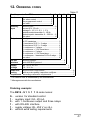
12. ORDERING CODES ......................................................... 61
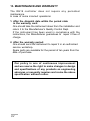
13. MAINTENANCE AND WARRANTY ................................. 62
4
1. APPLICATION
The RE19 dual loop controller/programmer is destined to control
temperature or other physical quantities, e.g. pressure, humidity,
level, converted into an electric signal..
It can independently control two objects or two physical quantities in one object, e.g. in two-zone furnaces.
This controller is available in three versions:
RE19 S
for standard (fixed set point) control,
RE19 P
for standard control or programmed control
- 15 programs with 15 segments in each
program,
RE19 V
for standard control by motorised valve control
- at choice, 2 algorythms of stepper control,
with or without feedback.
The controller can be equipped with the RS-485 interface with
MODBUS protocol.
The set of each delivered controller includes:
- RE19 controller
1 pc.
- users manual
1 pc.
- warranty card
1 pc.
- holder to fix in a panel
2 pcs.
- for controller ordered with interface:
- users manual with MODBUS protocol
- CD with RE19prg for configuration
1 pc.
1 pc.
When unpacking the controller, please check whether the
type and version code on the data plate correspond to the
order code.
5
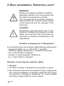
2. BASIC REQUIREMENTS, OPERATIONAL SAFETY
WARNING!
Warning of potential, hazardous situations.
Especially important. One must acquaint with
this before connecting the controller.
The non-observance of notices marked by
these symbols can occasion severe injuries
of the personnel and the damage of the
instrument
CAUTION!
Designates a general useful note. If you
observe it, handling of the instrument is made
easier. One must take note of this when the
instrument is working inconsistently to the
expectations.
Possible consequences if disregarded !
In the security scope, the controller meets following requirements:
- operational safety: acc. to EN 61010 -1 standard,
- resistance against interference in industrial environment:
acc. to EN 61000-6-2 standard,
- emission of electromagnetic interference:
acc. to EN 61000-6-4 standard.
Remarks concerning the operator safety:
1. General
♦ The RE19 controller is destined to be mounted in a panel.
♦ Non-authorized removal of the required housing, inappropriate
use, incorrect installation or operation create the risk of injury
to personnel or damage to equipment. For more detailed
information, please study the users manual.
6
♦ All operations concerning transport, installation, and commissioning as well as maintenance, must be carried out by qualified,
skilled personnel and national regulations for the prevention
of accidents must be observed.
♦ According to this basic safety information, qualified, skilled
personnel are persons who are familiar with the installation,
assembly, commissioning, and operation of the product and
who have qualifications necessary for their occupation.
2. Transport, storage
♦ Please observe the notes on transport, storage and appropriate
handling.
♦ Observe the climatic conditions given in technical data.
3. Installation
♦ The controller must be installed according to the regulation and
instructions given in this users manual.
♦ Before turning the controller on, one must check the correctness
of connection to the network.
♦ In case of the protection terminal connection with a separate
lead one must remember to connect it before the connection
of the instrument to the mains.
♦ When working on live controllers, the applicable national
regulations for the prevention of accidents must be observed.
♦ The electrical installation must be carried out according to the
appropriate regulations (cable cross-sections, fuses, PE
connection).
Additional information can be obtained from the users manual.
♦ The documentation contains information about installation in
compliance with EMC (shielding, grounding, filters and
cables). These notes must be observed for all CE-marked
products.
♦ The manufacturer of the measuring system or installed devices
is responsible for the compliance with the required limit values
demanded by the EMC legislation.
7
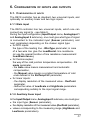
4. Operation
♦ Measuring systems including RE19 controllers, must be equipped
with protection devices according to the corresponding
standard and regulations for prevention of accidents.
♦ After the controller has been disconnected from the supply
voltage, live components and power connections must not be
touched immediately because capacitors can be charged.
♦ The housing must be closed during operation.
5. Maintenance and servicing
♦ Please observe the manufacturers documentation.
♦ Read all product-specific safety and application notes in this
users manual.
♦ Before taking the controller housing out, one must turn the
supply off.
♦ The removal of the controller housing during the warranty
contract period may cause its cancellation.
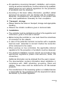
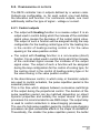
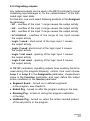
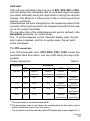
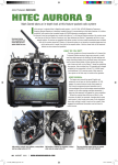
sensor 1
equalizer
connection
connected to PE
sensor 2
Fig. 3.1. Connection of two sensors.
8
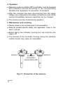
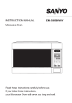
3. INSTALLATION
The controller is destined to be mounted in panels or cubicles.
One must prepare a hole in the panel of 92-0.5 x 92-0.5 mm.
The material thickness which the panel is made of cannot exceed
15 mm. One must introduce the controller from the panel front
without turning the supply on. After introducing the controller into
the hole, fix it by means of holders. Make the connection of external
signals acc. to fig 3.4. and 3.5.
In case of the controller operation in an environment with high
interference one must apply external filters. It is recommended to
use shielded wires connected with the PE wire of the supplying
network on the controller input. As the power lead, use a two-wire
cable. The wire cross-section should be chosen in order to assure
the cable protection in the case of a cable short-circuit from the
device side, by means of an installation cut-out.
On the application with two sensors metalic housings of sensors
must be connected to PE (see fig.3.1)
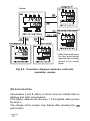
Fig. 3.2. Controller overall dimensions.
9
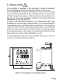
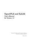
Supply
Output 1
Output 2
Output 3
Output 4
17 18 19 20 21 22 23 24 25 26 27 28 29 30 31 32
Supply
A
+ I
+ OC +
U,0/15V
RS-485
B GND
-
+ I
+ OC +
U,0/15V
+
+ OC -
+
-
+ OC -
+
-
16 15 14 13 12 11 10 9 8 7 6 5 4 3 2 1
Interface
RS-485
Logic
input
Input 3
Input 2
Input 1
Fig.3.3. Description of the terminal strip.
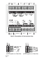
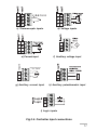
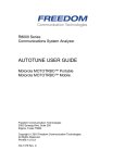
a) RTD inputs in a 2-wire line
10
b) RTD inputs in a 3-wire line
d) Voltage inputs
e) Current input
f) Auxiliary voltage input
+
11
10
9
Current source
0/4...20mA
-
Input 3
c) Thermocouple inputs
g) Auxiliary current input
h) Auxiliary potentiometric input
i) Logic inputs
Fig.3.4. Controller input connections.
11
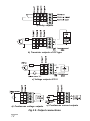
a) Relay outputs
b) Transistor outputs of OC type
c) Voltage outputs 0/15 V
d) Continuous voltage outputs
e) Continuous current outputs
Fig.3.5. Output connections.
12
4. SERVICE
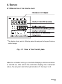
4.1. DESCRIPTION OF THE FRONTAL PLATE
* The display of set point is flickering when the set point is beyond the loop
control range.
Fig. 4.1. View of the frontal plate.
After the controller turning on, the test of displays and annunciators
is carried out, after which the controller displays the measured
value, the set point and other parameters of the loop I or II.
13
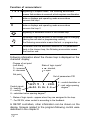
Function of annunciators:
1 2 3 4
signalling of outputs states; the flickering annunciator
means that an alarm is occurred, which requires a confirmation
I
data on displays and operating mode annunciators
concern the loop I
II
data on displays and operating mode annunciators
concern the loop II
signalling of automatic control in the chosen loop
information that the set point in the chosen loop is changing
(during the soft-start or programming control),
the flickering annunciator means the lock or program stop
A
information that the automatic selection of PID parameters
lasts in the chosen loop, the flickering annunciator means
the function end.
Following information about the chosen loop is displayed on the
character display:
Change of set point
(soft-start):
ä - increase,
æ - decrease
Set point
State of logic inputs*
- shorted,
- open
Set of parameters PID
SP1ä
PID1
Control signal:
H=50.0% E= 0.6
H - heating,
C - cooling
U - calculated valve opening degree**
E - control deviation or
Z - real valve opening
degree**
* - States of logic inputs - appear when they are assigned to the loop.
** - For RE19V, when control is according to the feedback
In RE19P controllers, other information can be shown on the
display. Screens related to the program-following control were
described in the chapter 8
14
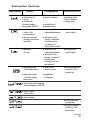
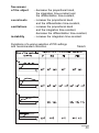
Push-button functions
Push-button
Control
l fast change of
Configuration
l input to submenu
set point
l screen with
information about
the program (RE19P)
l acceptation of
parameter value
l selection of the
l selection of the
screen with
measurements
l during 3 seconds switching on manual
operation
menu and parameters
l switching of the
circuit for heatingcooling control
l decrease of the
control signal
l during the value
change - decrease
of number value
or selection of
the previous position
l switching
l selection of the
l increase of the
l switching on the
l return to the
l turning the manual
l during 3 seconds
l resignation
of loops
configuration menu
menu and parameter
l during the value
change - increase of
number value
or selection of the
next position
previous menu
control signal
control off in the
current loop
and
l
start of the control from the
indicated segment (RE19P)
and
of changes
l
stop or restart
of the control
and and
- call of the hiding
mode menu
l alarm erasing
and
Manual operation
l monitoring of the
second loop
l turning the manual
control on in the
second loop
15
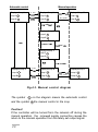
Control
1)
After 60 seconds since
the last push-button
pressure, the controller
returns to the control
mode.
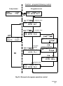
Fig.4.2. Transition diagram between controller
operation modes
4.2. LOOP SELECTION
Annunciators I and II inform, to which loop are related data on
displays and other annunciators:
If I is lighted, data concern the loop 1; if II is lighted, data concern
the loop 2.
The change of the chosen loop follows after pressing the
push-button.
16
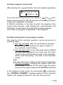
4.3. FAST CHANGE OF THE SET POINT
After pressing the
push-button, the scren appears (example):
Set point SP1
0050.0
↵
One must set the new set point by means of
and
pushbuttons and accept it by
. The pressure of the
push-button
causes the resignation of change.
In RE19P controllers, in the loop for which the program is the
source of the set point , after pressing the
push-button, the
information screen about the performed program appears.
The control of programs is described in the chapter 8
4.4. STOP AND RESTART OF THE AUTOMATIC CONTROL
The steering of the controller operation can be carried out in
following ways:
1. from the keyboard: after the simultaneous pressure
of
and
push-buttons, the stop or restart of
the automatic control follows
2. from the logic input: if one of the logic input is defined
as STOP and assigned to the loop, then the short-circuit of this input causes the stop of the automatic
control, and the opening - the return to the automatic
control.
Note:
The logic input has a higher priority than the keyboard.
3. from the computer: changing the register value 4123
for the loop 1 or 4124 for the loop 2 (see the users
manual for the serial interface with MODBUS protocol)
In the stopped control mode, the annunciator
is extincted,
the CONTROL STANDBY message appears on the character
display, and assigned outputs for the loop are turned off.
17
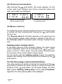
4.5. SCREEN WITH MEASUREMENTS
After pressing the
push-button, the screen appears. On this
screen, after input numbers and colons, measured values and
logic input states are displayed.
1: 850.0
3:-39.99
2:150.9
Screen in the controller
with an auxiliary input
1:1350.0
2:-39.99
Screen in the controller without
an auxiliary input
4.6. MANUAL OPERATION
The switching on the manual operation in the current chosen loop
is carried out after pressing and holding the
push-button
during 3 sec.
The Process value H inscription appears in the upper type line
of the character display when heating is realised in the loop, or
the Process value C inscription when cooling is realised in the
loop.
Heating and/or cooling control
In the lower type line of the character display, the output signal
value is displayed, which can be changed by the
or
pushbutton in the 0.0...100% range. The push-button holding causes
the increase of the control signal change speed.
For the control with two heating-cooling circuits, the switching
between the heating circuit and cooling circuit follows by the
push-button.
For the three-stage control (ValvePosition)
The valve opening is carried out during the pressure of the
,
push-button, however the valve closing is carried out during the
push-button. On the lower display, the valve
pressure of the
state is given: Opening, Closing, Stop. For the acc. to Feedback
algorythm, the valve opening state is also displayed.
18
When the second loop is not set in the manual operation, pressing simultaneously
and
push-buttons, one can turn its
monitoring on.
The control signal in the manually controlled loop remains on the
set value. During the loop monitoring, the controller configuration
is not possible. The return to the manual operation follows after
pressing any push-button.
and
push-buttons, we turn the
Pressing simultaneously
manual control on in the next loop, remaining the control signal in
the previous loop on the set value.
The return of the defined loop to the automatic operation follows
after pressing
.
The algorythm of possible manual control calls is presented on
the diagram 4.3.
19
Automatic control
Manual operation
3 sec
Displayed loop: I
Displayed loop: I
Loop: I
Loop: I
Loop: II
Loop: II
and
any pushbutton
Displayed loop: II
Loop: I
Loop: II
and
Displayed loop: II
Loop: I
Loop: II
and
and
Displayed loop: I
Loop: I
Loop: II
and
3 sec
Displayed loop: II
Displayed loop: II
Displayed loop: I
Loop: I
Loop: I
and
Loop: I
Loop: II
Loop: II
any pushbutton
Loop: II
Fig.4.3. Manual control diagram
The symbol
and the symbol
on the diagram means the automatic control
the manual control in the loop.
Caution!
If the controller will be turned from the network off during the
manual operation, the renewed supply connection causes the
return to the manual operation from the lately set output signal.
20
4.7. REVIEW AND CHANGE OF PARAMETERS
One can enter into the configuration mode after pressing in the
control mode. Following names are displayed on the character
display: menu, submenu, parameters and their values, and
push-button symbols.
vInputs/Outputs↵
or
, the
The symbol v means, that after pressing the
inscription shifts suitably into the next or previous position from
the chosen menu.
The symbol ↵ appears at the right side of the parameter and
means that after pressing the push-button we can:
♦
♦
♦
review the chosen submenu,
enter into the parameter change (after pressing the pushbutton,the symbol v is flickering before the being changed
parameter),
accept the value of the changed parameter.
Change of the parameter value:
♦ we can change the value of number parameters by means of
and
push-buttons. A single pressure of these pushbuttons changes the parameter value of 1; a longer holding
causes the value changes of 10, and next by 100, etc.
♦ for textual parameters, successive values defined for the
being changed parameter appear on the display after
pressing the
or
push-button.
The acceptation of the introduced value follows after pressing
, and the resignation of the introduced change, after pressing
.
If during 20 sec., none of push-buttons has been pressed,
the controller enters into the parameter change mode, without
changing its value.
Caution! The change of parameters can be reserved only for
persons knowing the access codes.
21
There are three codes in RE19 destined for particular menu and
functions (see table 1, access code menu). If the access code for
the given menu is different from zero, then after entering into the
configuration mode, the controller asks about its value (during the
changing test of the first parameter of this menu, the Give the K
code message appears).
The return to the control mode follows after pressing the
pushbutton from the main menu or after 60 seconds since the last
push-button pressure.
4.8. MENU HIDING
After the configuration and checking the control on the object,
one can hide particular groups of parameters, remaining only
those which will be submitted to changes.
To hide the menu, one must:
- hold during ca 3 sec. the , push-button in the control mode till
the screen appearance:
v Input/Output
visible menu
Menu name
↵
Accessibility status
- select the menu which we want to hide and set the hidden menu
status.
In order to restore the hidden menu one must:
- hold during ca 3 sec. the
the screen appearance:
v Input/Output
hidden menu ↵
push-button in the control mode till
Menu name
Accessibility status
- choose the menu which we want to make accessible and set
the visible menu status.
22
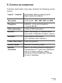
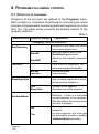
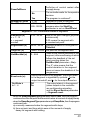
5. CONTROLLER PARAMETERS
Controller parameters have been divided into following groups
(menu):
Inputs / outputs
parameters defining analog inputs,
logic inputs and outputs
Set points
4 set points: SP1, SP2, SP3 and SP4
Programs
definition of set point programs
- only for RE19P
PID parameters
4 sets of PID parameters
Alarms
alarm parameters for outputs which
have been configured as alarm outputs
Modbus
transmission parameters
(for controller with interface)
Loop I and Loop II
loop configuration
Access codes
definition of security codes
Special
functions
start of the setting selection algorythm,
measurement of 2-wire line resistance,
return to factory settings, setting
the time of screen switching, change
of users language
23
24
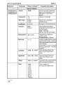
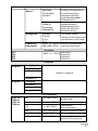
Submenu
Parameter
Range of changes1)
Only in
RE19P
controllers
Parameter description
Functions of binary inputs
Event Input 1
Event Input 2
Not used
The input function is not
assigned
STOP
Stops the automatic control
Alarms Reset
Releases stored alarms
Lockout
Locks parameter changes
from the keyboard
SP+1
Switches the set point on
the next value
PID+1
Switches the PID parameters
on the next set
SPiPID+1
Switches the set point and PID
parameter on the next set
SP+2
Switches the set point by two
positions
PID+2
Switches PID parameters by
two positions
SPiPID+2
Switches the set point and the PID
parameter set by two positions
HoldbackPrg
Stops the set point calculation
ProgramReset
Changes the open state into
shorted and causes the
program from the beginning
GotoNextSegm.
Changes the open state into
shorted state. Switches the
realized segment on the next.
25
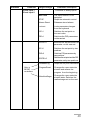
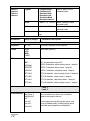
Submenu
Output 1
Output 2
Output 3
Output 4
Parameter
Assigned to
Range of changes1)
Loop1
(Out. 1 and 3)
Parameter description
Assignment of outputs
to the loop or input
Loop2
(Out. 2 and 4)
In. 1
In. 2
In. 3
In1+In2+Ine3
In.bin 1
(In3 appears only
in controllers with
an auxiliary input)
In.bin 2
In.bin 1 neg
In.bin 2 neg
Not used
Function
Definition of the output operation way:
Not defined
26
Heating
(Out.1 and 2)
Reverse control (in the valve
motorized control, valve
opening)
Cooling
Direct control (in the valve
motorized control, valve
closing)
Alarm
(Out.3 and 4)
Alarms (see menu: Alarms)
Event
Signalling in set point
programmer control (see
parameter: Sign.Source
in RE19P)
Retransmission
Retransmission of
continuous signals (See
parameter: Sign.Source)
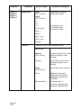
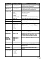
Submenu
Parameter
Source 3)
Range of changes1)
Set Point
ProcessValue
Deviation
Parameter description
Quantity retransmitted on
the continuous output
assigned for the loop.
(only when Function =
Retransmission)
Operation source of the
signalling output in
programming control
(only in RE19P, when
Function = Event)
Segment
EndedPrg
RunningPrg
HoldbackPrg
AnalogType
0-20 mA
4-20 mA
0-10 V
0-5 V
LowAnalog
HighAnalog
-999.9... 0 ...5553.6 4) Range of retransmitted
-999.9..100 ...5553.6 value [physical units]
For analog outputs,
selection of the linear signal
and definition of the range
Set points
SP1
SP2
SP3
SP4
-999.9... 0 ...5553.6
Set point 1
Set point 2
Set point 3
Set point 4
Programs
Program 1
ConfigPrg
Segment 1
,
.
Details in chapter 8
Segment 15
Program 15
ConfigPrg
Segment 1
.
Segment 15
PID parameters
PID1 set
PID2 set
PID3 set
PID4 set
XP
0.0...30.0...6500.0
Proportional band
[physical unit]
ti
0...300...9999
Integration time-constant [sec.]
td
0...60...3000.0
H
0.0...1.0...999.9
Differentiation
time-constant [sec.]
Hysteresis [physical units]
to
1...20...999
Pulse repetition period [sec.]
Y0
0.0...100.0
Correction of the control
signal for PD control [%]
27
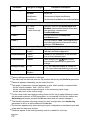
Alarms
Alarm 1
Alarm 2
Alarm 3
Alarm 4
TypeAl
FullScaleHigh
FullScaleLow
DeviationHigh
DeviationLow
DeviationBand
Deviationinband
SP.Al.
-999.9... 0 ...5553.6 Alarm operation value
[physical units]
0.0...1.0...999.9
Hysteresis for the alarm
[physical units]
Hi.Al.
Latch
Parameter
Range of changes
Yes,
no
Kind of alarm on the
indicated output
Alarm store
Parameter description
Modbus
Address
0...247
Controller address in the network
Baud
2400
4800
9600
19200
Baud rate [bit/sec.]
Transmission mode :
Mode
Off
off - transmission turned off
ASCII8n1
ASCII, 8 data bits, without parity check, 1 stop bit
ASCII7E1
ASCII, 7 data bits, parity check, 1 stop bit
ASCII7o1
ASCII, 7 data bits, odd parity check,1 stop bit
RTU 8n2
RTU, 8 data bits, without parity check, 2 stop bits,
RTU 8E1
RTU, 8 data bits, parity check, 1 stop bit,
RTU 8o1
RTU, 8 data bits, odd parity check, 1 stop bit
RTU 8n1
RTU, 8 data bits, without parity check, 1 stop bit
Loop 1
Loop 2
ProcessValue
28
In1 (loop I)
In2 (loop II)
In3
In1+In2
In1+In3
In2+Ine3
Input number from which the controlled
signal in the loop is read out.
For the signal comming from two inputs , one
must give additionally, coefficients by which
particular input signals are multiplied by.
Parameter
Range of changes
Parameter description
Multiplier A
-9.9...1.0...9.9
Coefficient, which the first component of the
controlled signal is multiplied by.
Multiplier B
-9.9...1.0...9.9
Coefficient, which the second component of
the controlled signal is multiplied by.
Kind of control realized in the loop:
ControlType
None
- the loop is not used
Heating
- reverse control
Cooling
- direct control
Heat-Cooling5)
- control with two lines (heating and cooling)
Valve Pos.
- three-stage step control (only in RE19V)
Ct1LowLimit
-999.9... 0....5553.62)
Ct1HighLimit
-999.9.. 100..5553.62)
These parameters define the control range
and the range of set point changes in the loop
(physical units)
SetPoint
SP1 (loop I)
SP2 (loop II)
SP3
SP4
REM
PRG5)
Set point assigned to the loop
(REM -from the auxiliary input; PRG - set
point from the program - Only in RE19P)
ProgramNr
1...15
The set point program number assigned to
the loop - only in RE19P
Ramp Rate
0.00...99..99
Accretion of the set point during the soft-start
(physical units /min) , only for SP1...SP4
0.0 means, that the soft-start is turned off
PID Set
PID(1) Set 8)
PID(2) Set 8)
PID1 (loop I)
PID2 (loop II)
PID3
PID4
Set of PID parameters assigned to the loop
Dead band
0.0..1.0..999.9
Displacement between two lines during the
control of heating+cooling type [physical units]
Dead band
0.0..1.0..999.9
Dead band in the valve type control
[physical units]
Feedback
no
yes
Event inputs
Not used
In.Log1
In.Log2
In.Log1+2
Algorythm for the valve control (only in
RE19V)
Allocation of logic inputs to the loop
29
Parameter
Range of changes
Parameter description
Algorythm of PID parameter selection
Autotuning
No use5)
turned off
Identification
On the base of object identification
Oscilllations
On the base of oscillations around the set point
Access codes
0...9999
0 means
a lack of security
Code 1
Security code for the Input/Output and
Modbus menu and the function of two-wire
line resistance measurement.
LineResistMeasur.
Code 2
Security code for PID Parameters
and Alarms menu
Code 3
Security code for Loop 1 and Loop 2 menu
and calling the function of automatic setting
selection - PID Selection
Special Functions
Loop 1
Loop 2
PID selection6)
LeadResistance
Input 1
Input 2
Default Values
Reset
Change of loop
0...20
Language
Polish
English
7)
Starts the algorythm of setting selection
defined in the loop configuration.
Measures the resistance of the two-wire
line on the indicated input.
push-button,
After pressing the
the controller restores factory parameter
settings.
0..2 - the alternate display is turned off
3..20 - time of the loop switching in seconds
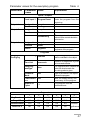
1)
Factory settings are printed in bold type
2)
The value has the decimal point on the position defined by the DecPoint parameter
3)
Parametr appears depending on the output function
4)
The range of parameter changes depends on that, what quantity is retransmitted:
- for the control deviation: from -100.0 to 100.0
- for the controlled and measured signal: in the measuring input range
- for the set point: in the control range
5)
For the control with two heating-cooling lines and for the program-following control,
the automatic selection of PID parameters is not possible, and for this reason the
Autotuning parameter accepts the No use value and one cannot change it.
6)
The function appears only when during the loop configuration, the Autotuning
parameter is set on a value different from No use
7)
The function appears only when during the input configuration a resistance input with
a two-wire line has been chosen
8)
Positions appear if the heating-cooling control is realized in the loop.
30
6. CONFIGURATION OF INPUTS AND OUTPUTS
6.1. CONFIGURATION OF INPUTS
The RE19 controller has as standard, two universal inputs, and
optionally an auxiliary linear and two logic inputs.
6.1.1 Main input
The RE19 controller has two universal inputs, which one can
connect any signal to - see table 9.
During the input configuration (Input/Output menu, AnalogInput 1
and AnalogInput 2 submenu), one must give what type of signal
is connected to the indicated input (Sensor parameter), and
next, parameters depending on the chosen signal type:
♦ for RTD inputs:
the type of the leading line - WireType parameter; in case
of a two-wire line give the LeadResist. line resistance
(or use the special function of line resistance measurement:
LeadResistance),
♦ for thermocouples:
the way of the cold junction temperature compensation - CJ
mode parameter,
- the Auto value means measurement and automatic
compensation,
- the Manual value means a constant temperature of cold
ends defined in the ExtTempCJC parameter,
♦ for linear inputs:
- the display resolution of the measured value - DecPoint
parameter,
- define the value of LowScale and HighScale parameters
corresponding suitably to the input signal range.
6.1.2. Auxiliary linear input
In the Input/Output menu, AnalogInput 3 submenu, one must give:
♦ the input type (Sensor parameter),
♦ the display resolution of the measured value (DecPoint parameter),
♦ values corresponding to the measuring range (HighScale and
LowScale parameters).
31
The auxiliary input can be used as:
♦ controlled signal for any loop (as an independent input or as
a constituent for a complex controlled signal, e.g. sum or
difference of signals),
♦ set point for an optional loop - then, set the Set point parameter
on In3 during the loop configuration,
♦ auxiliary measuring point - the value measured on the input can
be seen on the measuring screen,
♦ feddback from the valve, on the base of which the valve type
control algorythm is realized (only in RE19V).
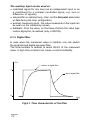
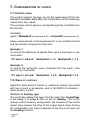
6.1.3. Digital filter
In case when the measured value is instable, one can switch
the programmed digital low-pass filter.
The time-constant is defined to reach 99.9% of the measured
value. A high time-constant can cause a control instability.
PV
without a digital filter
1
with a digital filter
0
t[s]
Fig.6.1. Time characteristic of the filter.
32
6.1.4. Logic inputs
Logic input functions are defined during the input configuration
(Input/Output menu) by Event Input 1 and Event Input 2
parameters. Next, in loop 1 and/or loop 2 menu, one must
assign logic inputs to particular control loops. One can allocate
one or both logic inputs to one loop.
Functions of logic inputs:
no used
the state of the logic input does not influence
the controller operation
Standby
the contact short-circuit means the turning
of controlled outputs and alarms off.
The input opening causes the return to the
automatic control.
AlarmsReset
the contact short-circuit causes the turning
of stored alarms off,
Lockout
the contact short-circuit causes the locking
of parameter changes during the controller
configuration - After pressing the
pushbutton, the ChangeLocking! message
appears. The holdback mode does not
concern SP1...SP4 set points.
SP+1
for fixed set point control - the short-circuit
of contact causes the switching of the set
point on the next from the value set {SP1, SP2,
SP3, SP4}. For the SP4 set point, the next set
point is SP1. The switching of the set point
takes into consideration the accretion rate of
the set point in the loop (soft-start).
The opening of contacts causes the return
to the previous set point.
33
PID+1
the contact short-circuit causes the switching
of the PID parameter set on the next set {PID1,
PID2, PID3, PID4}. For the PID4 set, PID1 is the
next. The switching between parameter sets
is percussiveless (the control signal changes
fluidly).
SPiPID+1
the contact short-circuit causes the switching
of the set point on the next and the PID
parameter set on the next.
SP+2
the contact short-circuit causes the switching
of the set point by two positions from the
value set {SP1, SP2, SP3, SP4}. E.g. SP1 will
be switched on SP3, SP4 on SP2, etc.
The contact opening causes the return to the
previous value.
PID+2
the contact short-circuit causes the switching
of the PID parameter set by two positions from
the {PID1, PID2, PID3, PID4} set.
SPiPID+2
the contact short-circuit causes the switching
of the set point and PID set by two positions
from suitable sets.
HoldbackPrg
the contact short-circuit causes the stoppage
of the set point counting. The control is
carried out acc. to the last counted value.
The contact opening causes the program
continuation (only in RE19P).
ProgramReset
The change of contact state, from opened to
short-circuited, causes the return of the
program to the initial state (only in RE19P).
GotoNextSegment The change of contact state, from opened to
short-circuited, causes the jump to the next
segment in the program (only in RE19P).
34
6.2. CONFIGURATION OF OUTPUTS
The RE19 controller has 4 outputs defined by a version code.
Outputs are configurable, i.e. for each output, one must define
the allocation and function. For continuous outputs, one must
additionally define the type of signal - voltage or current.
6.2.1. Control outputs
♦ The output with Heating function is a reverse output. It is an
output used in control during which the increase of the controlled
signal value causes the decrease of the output signal value.
The output of such a function will be assigned during the loop
configuration for the heating control type or for the heating line
in the control of heating+cooling control or for the valve
opening in the valve position control.
♦ The output with Cooling function is a non-reverse (direct)
function. It is an output used in control during which the increase
of the controlled signal causes the increase of the output
signal value. The output of such a function will be assigned
during the loop configuration for the control of cooling type, for
the cooling circuit in the control of heating-cooling type or for
the valve closing in the valve position control.
In the discontinuous control, in which relay or transistor outputs
are used to control actuators, the pulse repetition period is the
essential parameter.
This is the time which elapses between successive switchings
of the output during the proportional control. The duration of the
pulse repetition period can be matched depending on object
dynamic properties and suitably the output device. For quick
processes it is recommended to use SSR relays. The output relay
is used to control contactors in slow-changing processes.
The use of a high pulse repetition period to control quick-changing
processes can give undesirable effects in the shape of oscillations.
Theoretically, the smaller the pulse repetition period, the better
35
control is, however, for the relay control, the pulse repetition period should be as higher as possible in order to prolonge the relay
life.
The to pulse repetition parameter is given during the definition
of PID parameters in the PIDk Set menu.
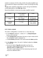
Recommendations concerning the pulse repetition period:
Output
Electromagnetic
relay
Pulse repetition
period to
recommended >20 sec
min. 10 sec
Transistor
output
Load
2 A/230 V a.c.
or contactor
min. 5 sec
1 A/230 V a.c.
1...3 sec
semiconductor
relay (SSR)
6.2.2. Alarm outputs
The alarm configuration is carried out in a two-step way:
1. In the Output k submenu - where k=1...4 (Outputs/Inputs
menu), one must set:
in the Assigned to parameter, the loop or input number which
the configured input is assigned to,
In the Function parameter, one must choose the Alarm position.
♦
♦
2. In the Alarms menu, for each of defined outputs as Alarm,
one must set:
♦
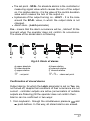
The kind of alarm (TypeAl parameter, see fig. 6.2.)
The alarm output assigned to the loop can act as an
absolute alarm or relative alarm.
The alarm output assigned to the measuring input can act
only as an absolute alarm.
36
The set point - SP.Al.- for absolute alarms is the controlled or
measuring signal value which causes the turn of the output
on. For relative alarms - it is the value of the control deviation
value which causes the turn of the output on.
♦ Hysteresis of the output turning on - Al.HY. - It is the zone
around the SP.Al. value, in which the output state is not
changed.
♦ Alarm store - (Latch parameter)
♦
Yes - means that the alarm occurrence will be latched till the
moment when the operator does not confirm its occurrence.
The diode of the stored alarm is flickering.
a)
b)
c)
d)
e)
f)
Fig.6.2. Kinds of alarms
a) upper absolute
b) lower absolute
c) upper relative
SP
- set point
d) lower relative
e) external relative
f) internal relative
SP.AL. - alarm set point
Confirmation of stored alarms
Output alarms, for which the Latch parameter is set on Yes, are
not turned off, despite that conditions of their occurrence are not
current - controller outputs are active (annunciators of suitable
outputs are flickering) till the operator does not confirm them.
Alarms can be confirmed in two ways:
1. from keyboard - through the simultaneous pressure
and
push-buttons. In this way, all stored alarms are erased.
37
2. by logic input - if one of the logic input is configured as
Reset.Alarms and assigned in the loop in the Event Inputs
parameter, then the short-circuit of this input causes the reset
of alarms related to this loop.
6.2.3. Retransmisssion outputs
Continuous outputs can be used to the retransmission of the
chosen quantity, e.g. in order to record the temperature in the
object or copy the set point in multi-zone furnaces. For this aim,
during the configuration of the continuous output, one must:
♦
♦
♦
♦
choose the Retransmis. value in the Function parameter,
choose the retransmitted signal in the Source parameter
for outputs assigned to the loop:
- ProcessValue - controlled signal,
- Deviation - control deviation,
- Set Point - set point,
choose the type and range of the continuous output:
0-20 mA, 4-20 mA, 0-10 V, 0-5 V
define controlled signal values corresponding to output
ranges - see fig. 6.3. This allows to retransmit the chosen
quantity in the interested range with a satisfied precision.
Fig.6.3. Calibration of the retransmission continuous output
38
6.2.4 Signalling outputs
Any optional outputs can be used in the RE19 controller to signal
measuring input damages or for the retransmission of the indicated logic input state.
For this aim, one must select following positions in the Assigned
to parameter:
- In1 - overflow of the input 1 range causes the output activity
- In2 - overflow of the input 2 range causes the output activity
- In3 - overflow of the input 3 range causes the output activity
- In1+In2+In3 - overflow of the range of any input causes
the output activity
- Logic 1 used - short-circuit of the logic input 1 causes
the output activity
- Logic 2 used -short-circuit of the logic input 2 causes
the output activity
- Logic 1 not used - opening of the logic input 1 causes
the output activity
- Logic 2 not used - opening of the logic input 2 causes
the output activity
In RE19P controllers, signalling outputs have auxiliary functions
used during the program-following control. One must choose
Loop 1 or Loop 2 in the Assigned to parameter, choose Event
value in the Function parameter, and next, define the output
action conditions in the Source parameter:
l
Segment Event - turned on in defined segments
in the program, see chapter 8,
l
Ended Prg - turned on after the program ending in the loop,
l
Running Prg - turned on during the program realization
in the loop,
l
Holdback Prg - turned on, when the active counted lockout
of the set point is in the program.
39
7. CONFIGURATION OF LOOPS
7.1. CONTROL SIGNAL
The control signal in the loop can be the measurement from the
indicated input (In1, In2, In3) or the combination of the measuring
values from two inputs.
The complex control signal is counted through the controller from
the formula:
Controlled
signal = MultiplierA*(measurement X) + MultiplierB*(measurement Y)
where measurement X and measurement Y, are suitably the first
and the second component of the sum.
Example 1
To control the difference of signals from input 2 and input 3, one
must write:
PV input = In2+In3;
MultiplierA = 1.0
MultiplierB = -1.0
Example 2
To control the arythmetic mean of signals from the input 1 and
input 2 one must write:
PV input = In1+In2;
MultiplierA = 0.5
MultiplierB = 0.5
7.2. KINDS OF CONTROLS
Apart from basic kinds of control i.e. heating or cooling, the control
with two circuits is accessible, and in the RE19V controllers valve position control.
Control of heating type
The controller realizes this type of control when the ControlType
in the Loop 1 or Loop 2 menu is set on Heating. That is the
reverse control (inverse), during which, the increase of the control
signal value causes the drop of the output signal value. During
the configuration, the output assigned to the loop must have set
the Heating function.
40
Control of cooling type
The controller realizes this type of control when the ControlType
in the Loop 1 or Loop 2 menu is set on Cooling. That is the
non-reverse control (direct), during which, the increase of the
control signal value causes the increase of the output signal
value. During the configuration, the output assigned to the loop
must have set the Cooling function.
Control with two circuits of heating-cooling type
The controller realizes this type of control when the ControlType
parameter is set on Heating-Cooling. For each control circuit,
one must assign the PID parameter set - PID Set (1) and PID Set (2)
parameters. Moreover, one must define the Deadband parameter
- parameter which defines the set point for the second circuit.
During the configuration, outputs assigned to the loop must have
set the Heating and Cooling functions.
Fig.7.1. Control with two heating-cooling circuits
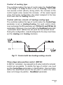
Three-stage valve position control (RE19V)
In RE19V controllers , two algorythms of valve control for actuator
control are accessible. To realize this type of control, one must
set the ControlType parameter on ValvePosition. One must also
define the dead band around the set point, in which the valve
does not change its position - DeadBand parameter.
41
Control
signal
100 %
circuit II-closure
circuit I-opening
SP
0%
XP
Dead band
XP
Controlled
quantity
Fig.7.2. Valve control
The valve opening is carried out through the output with Heating
function, and closing through the Cooling function. Two valve
control algorythms are at choice:
l
l
l
Without feedback signal from the valve - opening and closing
the valve is carried out on the base of PID parameters and
control deviation,
With feedback signal from the valve position device - opening
and closing the valve is carried out on the base of PID parameters,
control deviation and the valve position read out from the In3
auxiliary input. For this type of control, the counted position of
the valve U and the real position of the valve Z are displayed in
percentage on the information screen. The controller aims to
set the valve in the position U.
When the controller deviation is in the dead band, then instead
of the control signal, the inscription STOP is displayed.
7.3. CONTROL RANGE
The control range defined by Ct1LowLimit and Ct1HighLimit
defines the range of set point changes in the loop (i.e, during the
fast change of the set point) and start conditions of the object
identification algorythm.
7.4. SET
POINT IN THE LOOP
The set point in the loop can be one of four values defined under
SP1, SP2, SP3, SP4 names, the value read out from the In3
auxiliary input or one of the PRG programs (only in RE19P).
If the set point is not situated in the control range in the given loop,
then it is set on a suitable low and high range, and the set point
display is flickering.
42
Soft-start
If the value is controlled in the loop acc. to SP1, SP2, SP3 or SP4,
one can define the admissible rate of controlled signal changes
(so-called: soft-start) during the object start or during the set point
change. This allows to a mild access to the in-comming set point
without overshoots.
Instantaneous set point changes from the measuring value at the
moment of the counting start to the assigned set point to the loop
(or to the control threshold).
The accretion rate of the instantaneous set point is defined in the
RampRate parameter (in units/minute).
The ä symbol appears on the character display when the set
point value increases, and the æ symbol when the set point
value decreases.
7.5. PID
PARAMETERS
Four PID parameter sets: PID1,PID2, PID3 ,PID4 create the
parameter bank from which, one can profit during the loop configuration.
Control algorythms
Table 2
Algorythm
1)
2)
Parameter
XP
ti
td
Y01)
Histeresis
On/ Off
0.0
Without
significance
Without
significance
Without
significance
>=0.0
P
>0.0
0.0
0.0
>=0.02)
Without
significance
PI
>0.0
>0.0
0.0
Without
significance
Without
significance
PD
>0.0
0.0
>0.0
>=0.02)
Without
significance
PID
>0.0
>0.0
>0.0
Without
Without
significance
significance
The parameter is considered when ti=0
The parameter value is not taken into consideration for the valve control
without feedback signal from the valve .
The controller can automatically select PID parameters (see chapter 9.1.)
43
8. PROGRAM-FOLLOWING CONTROL
8.1. DEFINITION OF PROGRAMS
Programs of the set point are defined in the Programs menu.
Each program is composed of parameters concerning the whole
program and parameters concerning particular segments (no more
than 15). The table below presents parameters related to the
program definition
Table 3
Parameter name Ranges of changes
Explanation
ConfigPrg - program parameters
Definition of the value from which
the program begins from.
StartValuePrg
StartSP
Start from the set point in the
StartValuePrg parameter
StartWM
Start from the currently measured
value.
Time Unit
Time units for segments, for
which one must give the duration.
min:sec
hour:min
RampSegmType
Way to define segments in which
the set point is variable in.
Time
Ramp Rate
Duration of the segment
Accretion rate of the set point
Definition if there is a controlled
control deviation in the program.
After its overflow, the counting of the
set point is stopped.
HoldbackMode
No
Yes
44
minutes:seconds
hours:minutes
The program does not control the
deviations.
For each segment, one must give
the admissible deviation quantity
(HoldbackMode parameter)
Definition of control restart after
a supply decay.
PowerFailRecov
No
The controller waits for the operator
decision.
Yes
The program is continued1).
Number of cycles to carry out.
Initial set point value in the
program when the StartPrg
parameter is set on StartSPoint
Segment 1...15 - Parameters related to segments
NumberOfCycles
StartSPoint
1...99
-9999...
0.0...55536
RampRate (n)
n = 1...15
n = segment
number
SegDuration (n)
0.00...99.99
Target SP (n)
HoldBackVal (n)
Event outs (n):
Out State k
k=1...4
1)
Rate of set point changes [physical
units/minute]
0.00 means the segment with
a constant set point.
00:00...99:59 Segment duration in units given in
TimeUnit
-9999...55536 Set point on the segment end
Value of the control deviation in the
0...99.9
segment, after overflowing of which,
follows the deadlock of the set
point counting (when the
HoldBackVal parameter = Yes)2)
The 0 value means that the
control deviation in the segment
does not cause the deadlock of the
programmer.
During the review of the program, the output state
in the segment is signalled by symbols: for the
output turned off, and - for the output turned on.
Off
On
The output state k in the segment
(when outputs in the controller
are configured as signaling
and the Signal Source parameter
= Segment event.
- when the RampSegmentType parameter equal Time, then the program
continues from the set point and time which were at moment of supply decay.
- when the RampSegmentType parameter equal RampRate, then the program
continues from:
a) ccurrently measured value for segments with slope,
b) from set point and time which were at the moment of supply
decay for segment with holding.
45
2)
- for segments, which the set point increases in, the locking is realized from
the positive deviation (the object does not follow with the heating),
- for segments, which the set point decreases in, the locking is realized from
the negative deviation (the object does not follow with the cooling),
- for segments, which the set point is maintained on a constant level,
the locking in realized from the positive and negative deviation.
The program can have less than 15 segments. Then, after defining
the last used segment, one must give 0 for SegDuration and
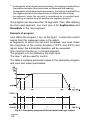
RampRate in the next segment.
Example of program
Lets define the program 1 acc. to the fig.8.1, in which the control
begins from the measured value in the object.
In segments, in which the set point increases, one must check
the magnitude of the control deviation (10.0oC and 5.0oC) and
signal, when the admissible deviation will be exceeded.
One must turn the fan on, in the last segment.
The program is to be started by the logic input.
The loop 1 will be used for control.
The table 4 contains parameter values in the examplary program
and input and output parameters.
Fig.8.1. Exemplary program of the set point and logic output
46
Parameter values for the exemplary program
Submenu
Parameter Value
name
Table 4
Explanation
Inputs / Outputs
Output 1
Event Input 1
Program Reset
Assigned to
Loop 1
Heating
Function
Output 2
Output 4
Assigned to
Loop 1
Function
Event
Source
HoldbackPrg
Assigned to
Function
Loop 1
Event
Source
Segment
The short-circuit of the input
starts the program from the
beginning
The output is active when the
lockout of the control deviation
is turned on
Output state in individual
segments of the program.
Programs
Program 1/
ConfigPrg
StartValuePrg
PVmode
Program begins from the current
value controlled in the object
Time Unit
hours:min
Duration of segments is given
in hours and minutes
RampSegmentType
time
For segments with variable set
point, the time to reach the
in-coming value is given
HoldBackMode
Yes
One must check if the object
follows the program
PowerFailRe- Yes
cov
After the supply decay, one
must carry on the program.
Number of
Cycles
1
The program must be
performed once
SegDuration
1
00:30
2
00:30
3
01:00
4
04:00
5
01:00
Segment
6
00:00
TargetSP
80.0
80.0
120.0
120.0
20.0
0.0
HoldBackValue
10.0
0.0
5.0
0.0
0.0
Without
State out 4
Off
Off
Off
Off
On
significance
47
Parametr name
Value
Explanation
Loop 1
PV input
Input 1
ControlType
Heating
SP Select
PRG
Program No
01
Event Inputs
Logic used
The acceptation of the program
number causes the control turn off
in the loop; the start of the program-following control is described in the
chapter 8.2. Control of programs.
During the program review, the output state in the segment is signalled by symbols: - for the output turned off, and - for the
output turned on.
8.2. PROGRAM - FOLLOWING CONTROL
During the program-following control , following information about
the chosen loop appears on the character display (called Loop
screen).
Program number acc. to which
the control in the loop is realized
State of the logic input
PID parameter set
Programmed
set point
PRG1
H=50.0%
Control signal:
H - heating, C- cooling
PID1
E= 0.6
Control deviation
Further information about the realized program are on the screen
(named: program screen) which is displayed after pressing the
.
48
Number of the
realized program
Number of the
realized segment
PRG1
sgm02 Lc1
00:30 15:39
Time expired from
the segment start
1)
Number of cycles which
remains to perform
Time remainded
to the cycle end1)
The time which remainded to the cycle end is displayed in units chosen in
the TimeUnit parameter. If a part of hours (minutes) exceed the value 99,
then only the component with the letter h (m), is displayed, e.g. 102 h means,
that 102 hours remained to the cycle end and the part with minutes is invisible.
Meaning of messages in the program status field
Table 5
Status field
Explanation
STOP
The control is turned off, e.g. after finishing
the program or by the operator through
and
. push-buttons. In this mode, the
control output is turned off.
E>Hlb
The control deviation is higher than the
admissible in the given object
EVHlb
The program is held the logic input
with function HoldbackPrg
rsHlb
The program is locked by the interface
Program in progress
During the program realization, beside the number of performed
segment, a symbol is displayed which informs how the set point
changes in the segment:
- when the set point increases
- when the set point decreases
_
- when the set point does not change
49
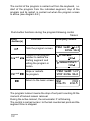
The control of the program is carried out from the keyboard, i.e.
start of the program from the indicated segment, stop of the
program and its restart, is carried out when the program screen
is active (see diagram 8.2.)
Push-button functions during the program-following control
Table 6
Push
-button(s)
Function
Calls the program screen.
and
and
Choice of the program
number to realize the
starting segment and
setting the program in
molion.
Stops or restarts
the program.
Exemplary screen
PRG1 Seg01
Lc1
04:06 90.0
ProgramNr
v01↵
SegmentStart
v01↵
PRG1 Seg01 Lc1
STOP 04:06 90.0
Return to the basic screen. PRG1
H=26.5%
PID1
E=0.5
The program lockout means the stop of set point counting till the
moment of lockout reason removal.
During the active lockout, the annunciator P is flickering,
The control is carried out acc. to the last counted set point and the
segment time is stopped.
50
Control - program-following control
Loop screen
PRG1
CONTROL
PID1
STOP
Program screen
PRG1
Seg01 Lc1
STOP 00:00 50.0
and
program start
PRG1 Seg01ä Lc1
00:01 50.1
and
program stop
PRG1 Seg01ä Lc1
STOP 01:51 75.0
PRG1
H=26.5%
PID1
E=0.5
and
ProgramNr
v01↵
and
program
restart
PRG1 Seg01ä Lc1
01:52 75.1
change of segment
SegmentStart
v05↵
PRG1 seg05- Lc1
01:52 150.0
program end
PRG1
seg01 Lc1
STOP 00:00 50.0
Fig.8.4. Example of program operation control
51
9. SPECIAL FUNCTIONS
One can call several functions from the Special Functions menu:
selection of settings, resistance measurement of two-wire lines,
return to factory settings, and loop switching.
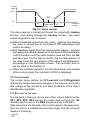
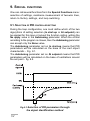
9.1. SELECTION OF PID CONTROLLER SETTING
During the loop configuration, one must define which of the two
algorythms of setting selection (In start-up or At setpoint) can
be applied for this loop or lockout the function calling, writing the
No apply value in the Autotuning parameter. When the control
according to the program is chosen, then the Autotuning parameter
can accept only the None value.
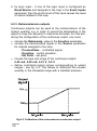
The Autotuning parameter set on In start-up means that PID
parameters will be calculated on the base of the inert object
characteristic - Fig. 9.1.
The Autotuning parameter set on At setpoint means that PID
parameters will be calculated on the base of oscillations around
the set point - fig. 9.2.
Fig.9.1.Selection of PID parameters through
the object identification method
52
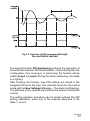
Fig.9.2. Selection of PID parameters through
the oscillation method
The special function PID Autotuning produces the algorythm of
the automatic selection of PID parameters, chosen during the loop
configuration. One must give, in which loop the function will be
called (Loop1 or Loop2). During the active autotuning , the diode
A is lighting.
After finishing the function, new PID settings are stored in the
assigned PID set to the loop. The controller returns to the control
mode with the New Settings! Message - The diode A is flickering.
The pressure of any optional key restores the screen of automatic
control.
The setting selection procedure can be broken without the PID
setting calculation, when one of the reasons described in the
table 7 occurs.
53
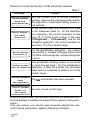
Reasons to break the function of PID parameter selection
Table 7
Message
Choice broken
from the
configuration
Choice broken.
Too small
deviation
Choice broken
Instability
Reason
For the chosen kind of control (heatingcooling, valve control or programmed control)
the algorythm of automatic setting choice is
not realized.
At the function start, the set point is to near
to the measured value i.e., for the identification algorythm, the control deviation is less
than 15 % of the control range in the loop
(Ct1HighLImit - Ct1LowLimit), and for the
oscillation algorythm, the control deviation is
less than 1% of the control range.
For the identification algorythm , the controlled quantity is instable (changes higher than
1% of the control range per minute) during over
2 hours.
The accessible heating power is too small
Choice broken to reach the set point - For the identification
Lack of reaction algorythm: if after 50 minutes the controlled
value has not increased at least by 3% of the
control range.
Choice broken
from
the keyboard
The
Choice broken
Error on
the input
An error occurs on the input
.push-button has been pressed.
In each of above case, the controller returns to the automatic control and displays a suitable message till the pressure of any pushbutton.
If for any reason, one cannot used proposed algorythms, one
must choose parameters applying following principles:
54
free answer
of the object
- decrease the proportional band,
the integration time-constant and
the differentiation time-constant,
overshoots
- increase the proportional band
and the differentiation time-constant,
oscillations
- increase the proportional band
and the integration time-constant,
decrease the differentiation time-constant,
instability
- increase the integration time-constant.
Symptoms of a wrong selection of PID settings
and recommended correction.
Table 5
55
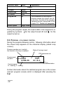
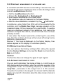
9.2. RESISTANCE MEASUREMENT OF A TWO-WIRE LINE .
In controllers with RTD sensors connected by a two-wire line, one
must introduce the line resistance value or take advantage of the
special LeadResistance function.
♦ Call the LeadResistance function
♦ Choose the AnalogInput1 or AnalogInput 2
♦ Short sensor terminals on the chosen input;
the resistance value is measured on the lower display,
♦ After the value stabilization, accepted it by the
push-button
A resistance o wires higher than 20 W will not be accepted by the
controller, and the Resist.Over High message appears on the
character display, till the pressure of any push-button. If question
marks are displayed instead of the resistance, that means the
resistance is higher than 420 W, sensor terminals have not been
probably shorted.
In case when the chosen input is the control input in one of the
loop, then the control in this loop will be turned off during the line
resistance measurement.
Morover, if this loop is displayed on the higher display, then
dashes appear on the display of controlled quantity.
9.3. RETURN TO FACTORY SETTINGS.
One can restore the factory settings after calling the special
function Factory Settings and accept the Reset command by the
push-button.
Caution!
The function does not change the type of input signals.
9.4. AUTOMATIC SWITCHING OF LOOPS
One can switch alternately the display of data on, in both loops on
LED displays and anunciators, when the controller operates in the
configuration mode. The switching frequency is defined in the
LoopTime parameter in the range from 3 to 20 seconds.
The write of a number in the range 0 to 2, means that the alternate
display is turned off - information about the lately chosen channel is
displayed.
56
9.5. CHANGE OF USER,S LANGUAGE
The Language parameter enables the change of language which
names of menu and parameters are displayed in, from Polish into
English or inversely.
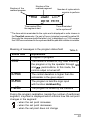
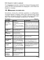
10. MESSAGES ON DISPLAYS
Sometimes, during the controller operation or configuration,
messages appear on displays, which inform about the way of loop
operation, emergency situation or conflict in the loop confirmation
way. A list of such messages is presented in the table 8.
Messages
Table 8
Message
Reason
error
- Check if the type of chosen sensor
Exceeding of
is compatible with the connected
the measuring range down
one.
and up.
Short-circuit in the sensor - Check if input signal values are
circuit or break in the sensor situated in the appropriate range.
- check if a short-circuit or break has
circuit.
not occurred in the sensor circuit.
CONTROL
STOP!
The automatic control
has been turned off
NO
CONTROL!
None of control
outputs has been
connected to the loop
Error in the
input
SP out of range The set point assigned to
No heating
output
the loop is not situated in
the loop control range
For the chosen type of
control in the loop, there
is no output with Heating
function
No cooling
output
For the chosen type of
control in the loop, there
is no output with Cooling
function
Lockout of
changes !
One of the logic input has
been defined as lockout of
parameter changes and is
shorted.
Incorrect
code of
changes
The given security code
does not correspond to the
previously set.
Procedure
Change the set point or the control
range of the loop
Check and if need be, correct
the assigned outputs and their
functions (Input/Output menu)
Check and if need be, correct the
assigned outputs and their functions
(Input/Output menu)
57
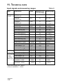
11. TECHNICAL DATA
Input signals and measuring ranges
Table 9
Input
Signal source
Symbol
Main input
1 and 2
Pt100 acc.
EN 60751+A2
Pt500 acc.
EN 60751+A2
Pt1000 acc.
EN 60751+A2
Ni100/1.617
Cu100/1.426
Termocouple FeCu-Ni
Termocouple Cu-CuNi
Termocouple NiCr-NiAl
Termocouple PtRh10-Pt
Pt100
0.1
-200...850oC
Pt500
0.1
-200...850oC
Pt1000
0.1
-200...850oC
Ni100
Cu100
J
T
K
S
0.2
0.2
0.2
0.2
0.1
0.2
Termocouple PtRh13-Pt
Termocouple PtRh30-PtRh16
Termocouple NiCr-CuNi
Termocouple NiCrSi-NiSi
Linear current 0...20 mA
Linear current 4...20 mA
Linear voltage 0...10 V2)
Linear voltage 0...5 V2)
Linear voltage 1...5 V2)
Linear current 0...20 mA
Linear current 4...20 mA
Linear voltage 0...10V
Linear voltage 0...5V
Linear voltage 1...5V
Potentiometric
transmitter 0...100 W
Potentiometric
transmitter0...1000 W
R
B
E
N
0...20 mA
4...20 mA
0...10 V
0...5 V
1...5 V
0...20 mA
4...20 mA
0...10 V
0...5 V
1...5 V
0.2
0.31)
0.1
0.1
0.05
0.05
0.05
0.05
0.05
0.05
0.05
0.05
0.05
0.05
-60...180oC
-50...180oC
-200..1200oC
-100...400oC
-200..1370oC
-50...1760oC
-50...1760oC
300...1820oC
-200..1000oC
-150..1300oC
0...20 mA
4...20 mA
0...10 V
0...5 V
1...5 V
0...20 mA
4...20 mA
0...10 V
0...5 V
1...5 V
0...100 W
0.1
0...100 W
0...1000 W
0.1
0...1000 W
Auxiliary
current input
Auxiliary
voltage
or potentiometric input
1)
2)
Error in the range: 500...1820oC
Source resistance: < 10 kW
58
Measurement error
in % of the range
Measuring range
Sampling period
Table 10
Type of signal on main inputs
Sampling period [sec]
Resistance thermometer in 3-wire line
1.0
Resistance thermometer in 2-wire line,
thermocouples
0.5
Way of output action:
♦ inverse (heating)
♦ direct (cooling)
Kind of set points:
♦ standard: (4 local SP1...SP4 at choice)
♦ external, from the auxiliary input
♦ programmed (15 programs of 15 segments each) in RE19P
controllers
Kind of outputs:
♦ relay
elecrtomagnetic relay,
contact load 230 V, 5 A,
♦ transistor
OC type, Umax = 24V, Imax = 20 mA
♦ transistor voltage
0/15 V, Imax = 20 mA
♦ voltage continuous
0...5 V, 0...10 V
at Rload ³ 500 W
♦ current continuous
0...20 mA, 4...20 mA
at Rload £ 500 W
Error of analog outputs
0.2% of the range
(0.3% for 0...5 V)
Serial Interface
♦ baud rate
♦ transmission orotocol
♦ modes
RS-485
2400, 4800, 9600, 19200 bit/s
MODBUS:
ASCII: 8N1, 7E1, 7O1;
RTU: 8N2, 8E1, 8O1, 8N1
1.5 sec.
♦ response time
59
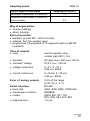
Reference and rated
working conditions
♦ supply voltage
♦ supply voltage frequency
♦ ambient temperature
♦ relative humidity
♦ external magnetic filed
♦ working position
85...253 V a.c/d.c
or 18...30 V d.c
40...400 Hz
5...23...40oC
< 85 % (without condensation)
< 400 A/m
any
♦ resistance of conductors
connecting the resistance
thermometer with
the controller
< 10 W/wire
Maximal power consumption < 9 VA
Weight
400 g
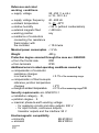
Protection degree ensured through the case acc. EN60529
♦ from the frontal side
IP40
♦ from terminals
IP20
Additional errors in rated operating conditions caused by:
♦ compensation of conductor
resistance changes
in a-3-wire line
< 0.1% of the measuring range
♦ compensation of thermocouple
reference junction temperature
changes
< 2oC
♦ change of ambient temperature
£ 0.1% of the measuring range/10K
Security requirements acc. EN61010-1
♦ installation category - III,
♦ pollution degree - 2.
♦ maximal phase-to-earth working voltage:
- for supplying circuits and relay outputs: 300 V
- for input circuits, continuous outputs,
transistor outputs and the interface: 50 V
Electromagnetic compatibility
♦ immunity
♦ emission
60
EN 61000-2
EN 61000-4
12. ORDERING
CODES
Table 11
Dual loop controller RE19
Version
Auxiliary
input
Outputs
X
X
X
X
X
X
for standard control ...................... S
for valve control ............................ V
for programmed control ................ P
on order* ....................................... X
without input ........................................... 0
current 0/4...20 mA ................................ 1
voltage 0...10 V, 0...5 V, 1...5 V
potentiometric transmitter 0...100 W
potentiometric transmitter 0...1000 W ... 2
on order* ............................................... X
4 relays ......................................................... 1
4 OC transistors ............................................ 2
1 transistors 0/15 V + 3 relays ..................... 3
2 transistors 0/15 V + 2 relays ..................... 4
1 continuous + 3 relays ................................ 5
1 continuous + 3 OC transistors ................... 6
2 continuous + 2 relays ................................ 7
2 continuous + 2 OC transistors ................... 8
1 continuous +1 transistors 0/15V+2 relays .... 9
on order* ....................................................... X
RS-485
Interface
without interface ..................................................... 0
with MODBUS protocol ........................................... 1
Supply
voltage
85...253 V a.c./d.c. .......................................................... 1
18...30 V d.c. ................................................................... 2
Additional
without extra requirements ........................................................ 8
testing
with an extra quality inspection certificate ................................ 7
requirements according customer,s requirements ** ...................................... X
* The version code is established by the manufacturer
** After agreement with the manufacturer
Ordering example:
The RE19 - S 1 5 1 1 8 code means:
S15118-
version for standard control
auxiliary input: 0/4...20 mA,
with 1 continuous output and three relays
with RS-485 interface
supply voltage: 85...253 V a.c./d.c.
without extra testing requirements
61
13. MAINTENANCE AND WARRANTY
The RE19 controller does not require any periodical
maintenance.
In case of some incorrect operations:
1. After the dispatch date within the period state
in the warranty card:
One should take the instrument down from the installation and
return it to the Manufacturers Quality Control Dept.
If the instrument has been used in compliance with the
instructions, the Manufacturer guarantees to repair it free of
charge.
2. After the warranty period:
One should send the instrument to repair it in an authorized
service workshop.
Spare parts are available for the period of ten years from the
date of purchase.
Our policy is one of continuous improvement
and we reserve the right to make changes in design
and specifications of any products as engineering
advances or necessity requires and revise the above
specification without notice.
62
63