1
WIFI-RS232
User Manual(v1.5)
1th page, 55 pages in all
TABLE OF CONTENTS
1.
2.
3.
4.
OVERVIEW......................................................................................................................4
1.1.
Main Function ...................................................................................................4
1.2.
Typical Applications..........................................................................................5
1.2.1. Wireless POS Machine.................................................................................5
1.2.2. Wirelsee Monitoring and Control System....................................................5
WORKING PRINCIPLE ..................................................................................................6
2.1.
Block Diagram ..................................................................................................6
2.2.
Parameter management .....................................................................................6
2.3.
Interconnection Model ......................................................................................8
2.3.1. Automatic Networking.................................................................................8
2.3.2. Manual Networking ...................................................................................10
2.4.
Encrpytion.......................................................................................................10
2.5.
Data transmission ............................................................................................11
2.5.1. RAW format ...............................................................................................11
2.5.2. UDP format ................................................................................................12
2.5.3. TCP format.................................................................................................13
TEST ENVIRONMENT GUIDE....................................................................................15
3.1.
Summary .........................................................................................................15
3.2.
Client Software................................................................................................17
3.3.
Server Software...............................................................................................18
3.4.
Parameter management ...................................................................................19
3.4.1. Parameter query/edit ..................................................................................19
3.4.2. Parameter Explanation ...............................................................................20
3.5.
Automatic networking.....................................................................................21
3.6.
Manual networking .........................................................................................22
3.7.
TCP Monitor Mode Test..................................................................................25
3.8.
Text Transfer Test............................................................................................27
3.9.
Document Trabsfer Test ..................................................................................28
3.10.
The Answers of Familiar Questions ................................................................30
SERIAL PROTOCOL.....................................................................................................33
4.1.
summarize .......................................................................................................33
4.2.
UART serial protocol ......................................................................................34
4.2.1. Data Format................................................................................................34
4.2.2. Transfer Mechanism...................................................................................35
4.2.3. Serial Configuration ...................................................................................36
4.3.
User Serial Control Protocol ...........................................................................36
4.3.1. Data Format................................................................................................36
4.3.2. Order of Starting to Scan Network.............................................................38
4.3.3. Message of Scanning Network Result........................................................38
4.3.4. Order of Starting to Connect to Network ...................................................39
4.3.5. Message of Network Connected ................................................................40
4.3.6. Order of Starting to Disconnect Network...................................................40
4.3.7. Message of Network Disconnected............................................................41
4.3.8. Setting Parameter Order .............................................................................41
4.3.9. Message of Setting Parameter Result.........................................................43
4.3.10. Inquiring Parameter Order .......................................................................43
4.3.11. Message of Inquiring Result.....................................................................44
2th page, 55 pages in all
4.3.12. Reset Order...............................................................................................44
4.3.13. Message of Finished Initialization ...........................................................45
4.3.14. TCP Connection order..............................................................................45
4.3.15. Message of TCP connection Status ..........................................................46
4.3.16. Message of TCP Failed Sending ..............................................................46
4.4.
Configuration parameters................................................................................46
4.4.1. System parameters .....................................................................................47
4.4.2. Network parameters ...................................................................................47
4.5.
Programme Guide ...........................................................................................50
4.5.1. The Example of Network Control..............................................................50
4.5.2. The Example of Parameters Setting ...........................................................51
4.5.3. The example of sending data......................................................................52
4.5.4. CRC-8 Algorithm Reference Implementation............................................53
4.6.
Modification Note of Serial Protocol ..............................................................54
3th page, 55 pages in all
1.
1.1.
Overview
Main Function
Support for UART data serial, four baud rate options: 19200 / 38400 / 57600 / 115200bps.
Wireless data rates support the 802.11b Standard, the maximum rate is 11Mbps.
Integrate the functions of 802.11 MAC protocol Softwares.
Support for the STA appliances in the Infrastructure Network.
Support for the OPEN/WEP mode authentication.
Support for the wep64/wep128/ccmp/wpi data encryption transmission in the
shared key mode
Support for the automatic networking mode and manual networking mode.
In the automatic networking mode,the module can automatically scan the
target network, and automatically connect when disconnection.
In the manual networking mode,operation of connect and disconnect is touched off by
order,this supports a flexible control space.
Suppport the network data transmission in RAW/UDP/TCP format.
Suppport seven groups of the basic parameters set,and can connect to seven target
networks the most.
Suppport to Config the parameters through user serial.
Suppport to upgrate the fireware on line by the internet.
4th page, 55 pages in all
1.2. Typical Applications
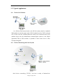
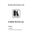
1.2.1. Wireless POS Machine
In a Wireless Bus System based on the WLAN technic,carheld or handheld
POS machine in each bus equips with a WLAN module based on UART serial,and
AP is fixed in the Bus Terminus.When bus reachs in the terminus,wireless POS
machine always does the indentification automaticly,then connects to the AP,and
Operational Data in POS mechines is uploaded to Data Center Server in Bus
Terminus through AP.
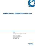
1.2.2. Wirelsee Monitoring and Control System
Serial devices networking( TCP/IP ) has been a trendy of Industrial-site
5th page, 55 pages in all
networking,but Field wiring and the following construction, transformation cost often
become a bottleneck of serial devices networking.WLAN modules embed in these
Monitoring and Control Terminals ,which support serial ,not only can absolves the
difficulty of wiring,but also reduces the construction cost,and it especially adapts to
the devices about Industrial Environment and Factory Automation Systems,Site
Monitoring System and etc.
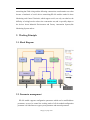
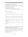
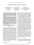
2. Working Principle
2.1. Block Diagram
2.2. Parameter management
WLAN module supports configuration parameters which can be modified,these
parameters are used to control the working mode of all the module.configuration
parameter is divided into two types:system parameter and network parameter.
6th page, 55 pages in all
System Parameter
It’s the parameter setting that used to control the work mode of the module,it
include:
Networking Mode
WLAN module supports two types mode:automatic networking and
manualnetworking.
Transparent Transfer Mode
WLAN module supports transparent transfer mode at serials, In need of special
note is that when it’s in the automatic networking and uses UDP protocol in Link Layer
at the same time,this mode can just be effective.
TCP Monitoring Mode
WLAN module supports the use of TCP listening mode when TCP protocol is used in
Link Layer, after this mode is used ,the WLAN module can be used as a TCP server,
waiting for client’s connection requests.
Baud Rate of Serial
WLAN module supports four kinds of baud rate:19200、38400、57600、
115200.
Device Physical Address
It’s the MAC address of WLAN module.
Network Parameter
It indicates the parameter that connecting to the target network needs to set,this
module supports to set seven target networks,so users can set seven groups of network
parameter.
Each group of network parameter include:
BSSID
The BSSID of target network,Its value is the MAC address of the AP used in
target network.Each AP owns their only and not repeated MAC address,then
this module uses BSSID to be the mark of different network.
Channel
It indicates the channel of the target network.This module supports Channel
1~14.
SSID
It indicates the SSID used by the target network.
Encryption Type
7th page, 55 pages in all
It indicates the encryption type used by the target network,the encryption
types this module supports include Non-encrypted,WEP,CCMP,WPI.
Key
It indicates the key used by the target network. According to different types
of encryption, key is not the same format.
Data format of the Link Layer
This module supports three data formats:RAW,UDP,TCP.
Physical Address of the Server
It indicates the MAC address of the Data Center Server(only used in RAW
format).
IP Address of the Device
It indicates WLAN module its own IP address(only used in UDP/TCP
format) .
IP Address of the Server
It indicates the IP address of the Data Center Server (only used in UDP/TCP
format).
Service Port
It indicates the server port number (only used in UDP/TCP format).
2.3. Connection Model
WLAN module supports automatic and manual this two modes for users to
choose.It should be regarded that,in the 1.3 and previous versions, when the WLAN
module is set to TCP Link Layer approach, the process of networking automatically
includes the process of networking with the TCP server.
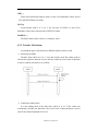
2.3.1. Automatic Networking
In automatic Networking mode, without any user intervention, WLAN module
automatically scan and connect to the network after the power-on reset.
If a situation occurred as the following, WLAN module will automatically
re-connect:
1、Connection is failed;
2、Network is disconnected;
8th page, 55 pages in all
3、The target network is rescanned.
4、Server disconnects the TCP connection when TCP Data format is used.
If a situation occurred as the following, WLAN module will automatically
scannetwork status:
1、The AP of the target network is off.
2、WLAN module leaves the signal coverage of AP.
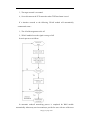
Its work processes as follows.
In automatic mode,all networking process is completed bu WAN module
automatically without any user intervention,to provide for users with one of the most
9th page, 55 pages in all
simple way.to success to connect the network,users only need to set at least one group
of basic parameters once at the first use.Then WLAN module will scan the network in
each power-on reset automatically, if the target network is Detected,networking will
be connected automatically,and user can receive the the message of success
networking after successful connection,then user can transport data normally.If the
network disconnected accidentally in the middle,the module can do automatic
connection.In the case the AP in the network is off or WLAN module has leaved from
the signal coverage of the network,WLAN module may do automatic scan until
scanning practicable network.
This module can set at most seven target network at the same time.When more
then one target networks in the current area,WLAN module may connect
automatically to the first practicable network.
2.3.2. Manual Networking
In the manual networking mode,users need to control connection and
disconnection of WLAN module by order.
2.4. Encrpytion
WLAN module supports WEP, WPI, CCMP these three data encypytion mode
and non-encryted OPEN mode.
WEP
In the encrpytion mode of WEP, user can set 4 groups of key,and choose one
group as tolerant sending key.the length of the key is divides into two styles:64
bit and 128 bit
64 bit key
Besides 24 bits stochastic data,the length of the key user needs to set is 40
bits,as 5 bytes.
128bit key
Besides 24 bits stochastic data,the length of the key user needs to set is 104
bits,as 13 bytes.
WPI
10th page, 55 pages in all
In the encrpytion mode of WPI,user needs to set 32 bytes key,broadcast is
achieved from AP automatically.
CCMP
In the encrpytion mode of WPI,user needs to set 16 bytes keybroadcast is
achieved from AP automatically.
2.5. Data transmission
In networking status,WLAN module transmit automatically the effective data that
has received between user serial (UART) and wireless network serial.
According to the user setting,the Data Link Layer of WLAN module can do the
data transmission in RAW, UDP and TCP data formats.
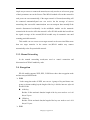
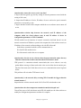
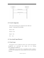
2.5.1. RAW format
It’s the raw data format,this format no longer do the additional encapsulation to
the user data in the transmission process of Link Layer, but directly change to 802.11
network frame to transmit.In this format,WLAN module uses the MAC address of the
server as the target address of data transmission.
Data transmission model is as follow:
11th page, 55 pages in all
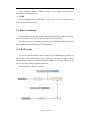
2.5.2. UDP format
UDP,that is User Data Protocol,It’s Connectionless Data Transmission Protocol
in TCP/IP protocal stack.UDP protocol supports unreliable data transfer,and does not
guarantee the integrity of the data.But UDP uses little network sourceand supports
quick data manage,therefore it’s suit for the occasions that the demand of
transmission real-time is strict ,but the demand of data integrity is low-rise,such as
Audio and video data transmission.In addition,using UDP format can achieve the
data broadcast.
When Link Layer of the WLAN module uses UDP format,the information
include device IP address, server IP address and service port number must set
accurately,if server and WLAN module are not in the same subnet,subnet mask and
gateway are must be set,otherwise they wouldn’t be able to communicate (the setting
of IP address and port number must accord with the provision of TCP/IP protocol).
Data transmission model is as follow:
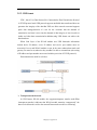
Transparent transfer mode
In UDP format ,WLAN module also supportstransparent transfer mode.What
istransparent transfer,it indicates that WLAN module transmite “transparently” the
data received from the serial to the network.Data transfer model is as following:
12th page, 55 pages in all
To get in transparent transfer status must fulfil the following conditions:
1、Using Automatic Networking mode;
2、Using UDP Link Layer data format;
3、WLAN module is in successful networking status;
What must need to notice,WLAN module gets in transparent transfer status,then
cannot receive user’s order from UART serial.(before using simulation environment
to do the testing and demonstration,please turn off the WLAN module client
software,and use general-purpose serial tools,such as Hyper Terminal,serial
debugging assistant,etc. to do the data transmission testting).
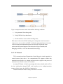
2.5.3. TCP format
TCP is connection-oriented Transmission Control Protocol,a virtual connection is
created between both sides of the communication.TCP supports reliable data
transmission,out-of-order, loss, damage and issues such as appear in the process of
transmission are all able to answer for comeback.
At using TCP format in Link Layer,strongly adviced,user should enable ACK at
the time sending data through UART serial, namely use the sending/responsion
manner to further ensure the reliability of transmission.
The data transmission midel of using TCP format is as follow:
13th page, 55 pages in all
TCP Monitoring mode
When Link layer is set to TCP format,WLAN module can not only be used as the
client to connect to the TCP server set in the network parameter,but also work as
TCP server after starting monitoring mode.To set system parameter can enable or
close TCP Monitoring mode,when the data format of Link Layer isn’t TCP,this
parameter can be neglected.According to the status of TCP monitoring mode,the
networking process of WLAN module is different:
Close TCP Monitoring
WLAN module has associated with AP successfully,then automatically
connect to the server contents with the network parameter setting,and returns the
message of successful networking to user side after building TCP connection with
the server,otherwise,return failed message.At the time,the process of the module
is the same with theWLAN module of 1.3 and previous versions which do not
support the TCP Monitoring mode.
Enable TCP Monitoring
WLAN module returns the message of successful networking to user side
after connect with AP successfully,then WLAN module get in TCP Monitoring
mode,it can accept extrinsic TCP connection requests.If user wish it works as the
client to connect to the server,you can use TCP Connection Order Control to
initiate the connection request.
This module does not support building multiple TCP connections at the same
time,if currently a TCP connection already exists,it can no longer receive or send new
connection requests.
14th page, 55 pages in all
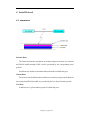
3. Test Environment Guide
WLAN module is as a functional unit,can only run during embedding in the
system.Therefore,we support the following simulation running environment for users
to do the module function testing.
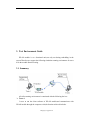
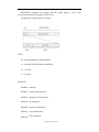
3.1. Summary
.
All of the running environment is constituted with the following devices:
Tester 1
It uses to run the client software of WLAN module,and communicates with
WLAN module through the computer serial,the function achieved includes:
15th page, 55 pages in all
1、Send control order to WLAN module;
2、Receive and analyse the message send by the WLAN module;
3、Set/demand the configuration parameters of WLAN module;
4、Cooperate with server software to run data transmission testing;
WLAN module
It’s composed by the STAU network card supports UART serial running this
software,the function achieved includes:
1、Wireless networking function;
2、Data transmission between serial and wireless network;
AP
It’s used to build a wireless network.
Tester 2
It’s used to run the server software of WLAN module,this computer must have
network connection,the function achieved includes:
1、Do the data transmission testing with client software;
2、Be the upgrating online server of WLAN module firmware.
16th page, 55 pages in all
3.2. Client Software
The client software connects to WLAN module through the computer serial,and
achieves the following functions:
Serial Configure
The choose of serial baud rate,includes 19200、38400、57600、115200.
Sending control order
Send control order to WLAN module by clicking the buttons,the order supports
include scanning network, join network,leave network,parameter configuretion, reset.
Receiving control message
Analyzing the control message received,and displaying the result in the export
window.
Parameters configuration
Analyzing and modifying the system parameters and the 7 groups of network
parameters of WLAN module.
In the status of networking,sending and receiving data including text data and
document through wireless network with server software.
17th page, 55 pages in all
Serial Data Detection
Be able to snatch at the data frames of serial communication,and can get the
dataframes of serial communication,be convenient for users to use UART serial
protocol to do the secondary development.
3.3. Server Software
Server software runs on the computer with the network connection
function.When the computer and WLAN module connect to the network built by the
same AP, then it can do the data transmission testing with the client software.
UDP Testing
Build a UDP server,set the Link Layer data format of WLAN module as
UDP,then you can do the data communication with it,including sending and receiving
text,receiving document.In this mode,the server does not support the function of
sending document.
TCP Testing
Build a TCP server, set the Link Layer data format of WLAN module as TCP,then
you can do the data communication with it,including sending and receiving text and
document.
Upgrate Online
18th page, 55 pages in all
Work as the online upgrate server,achieved remote firmware upgrade
functionality of WLAN module.
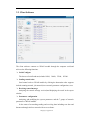
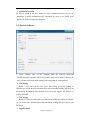
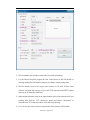
3.4. Parameter management
3.4.1. Parameter query/edit
Client software can be used to manage the parameter of WLAN module,the
following is to modify the encryption method of network parameters as an example to
illuminate the method of modifying parameter:
1、Click
the “parameter configuration” button(please don’t set the parameter during
transmission)
2、Choose parameter index
19th page, 55 pages in all
3、Select the choose box of encryption setting,and modify the encryption types.
4、Click the “parameter setting” button.
5、Modification is finished.
3.4.2. Parameter Explanation
Network parameter includes the parameter needed by connecting to AP and
server,this module supports 7 groups of network parameter setting,the meaning of
each parameter is that:
Parameter Index
The index number of the group of network parameter.
Channel、SSID、Encryption style、Key
These are all the configuration parameters,please refer to the setting of AP.
BSSID
It indicates the MAC address of the target AP.
The data format of Link Layer
It indicates the data format used by the transmission between WLAN module and
server,the setting here must be the same with the setting of the server which connects
to.(Note:the server software in this testing system can only support UDP and TCP
these two data formats)
Device ‘s IP address
It indicates the IP address of WLAN module,and it’s arbitrarily designated by
users,but it must be sure that the setting IP address is the legitimate IP address of the
tsrget AP and dosen’t be used.
What specially needs to explan,the address have nothing to do with the network
card’s IP address of the tester 1,which computer the client software run on.
Subnet Mask
It indicates the subnet mask of the network WLAN module exists in.
Gateway IP Address
20th page, 55 pages in all
It indicates the gateway IP address of the network WLAN module exists in.
Server IP Address
It indicates the IP address of the network card of tester 2.
Service Port
It indicates the monitor port of server,its setting must be the same with the server.
System parameter embodies one group,and it’s used to control the work mode of
WLAN module,the mode includes:
Networking mode
It indicates that users can choose auto and manual this two type in the parameters
of networking mode.
Transparent Transfer Mode
It indicates transfer format of serial data,and it’s able to be chose enableo or
close.What is needed to notice,transparent transfer function can only be effective
when networking mode is automatic and data format of server is UDP.Except this
instance,this parameter can be ignored.
Serial paud Rate
It indicates communication speed of serial,its configuration is the serial transfer
speed of the hardware of WLAN module,the serial speed setting of the client
software can refer to the serial setting column of the main window of the
software.The speed between both sides must be the same,otherwise the
communication between the client software and module can’t go along.
3.5. Automatic networking
In automatic mode,all process of networking is finished automatically by WLAN
module without user’s control,so that supports a most ordinary method.User only
needs to set at least one group of network parameter once,then WLAN module will
scan network automatically after power-on reset,if module has scaned the target
netwprk,then connects automatically,and sends the message of connection has
21th page, 55 pages in all
successed after successful connection,that is as follow.
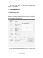
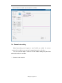
3.6. Manual networking
Manual networking mode supports a more flexible use method for user.user
cancontrol the module to scan, network, transport dataand etc. with order.
User can send all kinds of orders to WLAN module during using the client
software,the orders are as follow:
Connect to the network
22th page, 55 pages in all
1、Click the “Join” button;
2、Please choose the group network parameter what’s needed,then click “OK”;
3、Connect successfully;
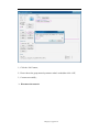
Disconnect the network
23th page, 55 pages in all
1、Click “Leave” button;
2、Disconnect successfully;
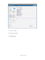
Scan the network
24th page, 55 pages in all
1、click “Scan” button;
2、return the scan result;
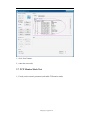
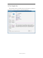
3.7. TCP Monitor Mode Test
1、Exactly set the network parameters,and enable TCP monitor mode;
25th page, 55 pages in all
2、WLAN module gets in monitor status after successful networking;
3、Use the Internet Explorer program in tester 2,and connect to WLAN module as
drawing method, fill in IP address and port according to actual setting value;
4、WLAN module receives the request and connects to IE with TCP,the client
software will show the message of successful TCP connection and HTTP request
data sent by IE from this connection;
5、Input random character string in the input window of the client software,click”text
sending”,then click the “TCP connection” button and choose “disconnect” to
disconnect the TCP connection,show as the following drawing;
6、User can see the content of the text input in the client software in IE window;
26th page, 55 pages in all
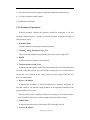
3.8. Text Transfer Test
WLAN module connects successfully, then use the client and server software at
the same time to do the text transfer test as the following drawing.
27th page, 55 pages in all
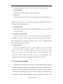
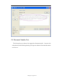
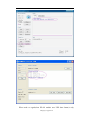
3.9. Document Trabsfer Test
The client and server software also support the document transfer between each
other,showed in the following drawing is the procees that the client sends document
to the server.
28th page, 55 pages in all
What needs to regard,when WLAN module uses UDP data format,it only
29th page, 55 pages in all
supports that document is sent by the client to the server,and UDP is
uncertaint,document transfer may be disconnected by network matter.to ensure the
transmission reliably,please use TCP format.
3.10. The Answers of Familiar Questions
Questions : Why the “ [Notice] Module disconnected ” message appeared at
thetime the client sends the control order?
Inspect that the serial setting of the client software is accurate or not;
Inspect that WLAN module is power-on or not;
Inspect that WLAN module is in transparent transmission mode;
Questions:Why the module may return failed connection?
The reason of failed connection is manifold possibility,
First,the target network can’t be used
a. Inspect that the power of AP is on and the configuration is accurate or not;
b. Scan network manuslly,be sure the target network can be scaned;
c. Inspect that the wireless mode of AP is be set to B or B/G mixed mode or not;
Second,parameter configuration about AP in network paramneter is not accurate
a. Inspect the configuration of WLAN module ,ensure channel,BSSID,SSID and
encryption setting is the same as the setting of AP;
Third,if Link Layer data format is TCP,the incorrectness of parameter configuration
about service in network paramnter also cause failed connection
a. Inspect that MAC address of server,IP address of device,IP address of server and
service port settting is accurate and legitimate or not,thereinto,
MAC address of server indicates the physical address of the network card in the
computer which the server software runs in.
IP address of server indicates the IP address of the computer which the server
software runs in.
Service port indicates the service port set in server software.
IP address of device indicates the IP address set for WLAN module,it must be in a
network sect with the IP of server.
30th page, 55 pages in all
Question:Why is my secret key always be incorrect?
The express method the client software of this system used may be different from
your AP and need to do the format conversion,the following is a example used 64bits
WEP key to express the conversion method:
The key of AP uses hexadecimal format:
In case the key of AP is 10 hexadecimal numbers: 1234567890
The after conversion express as 5 hexadecimal numbers:0x12, 0x34, 0x56, 0x78,
0x90
The key of AP uses ASCII format:
In case the key of AP is 5 ASCII bytes:abcde
The after conversion express as 5 hexadecimal numbers:0x61, 0x62, 0x63, 0x64,
0x65
(Please refer to the normal ACSII character set about the express of ASCII byte’s
hexadecimal, common christcross-row and number can use the following method to
count:
The hexadecimal number of character ‘A’ is 0x41,the charater ‘B’ is 0x42,and
reckon as this;
The hexadecimal number of character ‘a’ is 0x61,the charater ‘b’ is 0x62,and
reckon as this;
The hexadecimal number of character ‘0’ is 0x30,the charater ‘1’ is 0x31,and
reckon as this;
)
Question:why is that thing at using TCP format,failed connection or rapid
disconnection after successful connection always appear?
TCP connection is a imaginary connection,if the network connection disconnects
abnormally(such as power-off and manual reset),then the connection between WLAN
moduleand the srver can’t backout normally,and this causes reconnectd to the server
failed,the method of resolving the question is as follow:
a. restart the server software;
b. set different service port;
31th page, 55 pages in all
Question:why can not the server receive any data?
a. Inspect that encryption type and key setting in network parameters accord with the
setting of AP or not;
b. Inspect that IP address of device, IP address of server and service port in network
parameters set accurately or not;
c. Inspect that the firewall of the computer which the server software runs on turns off
or not;
Question:what relation ship between the network card IP address of the
computer which the client software runs in and IP address of device in
configuration parameters of WLAN module?
WLAN module has the function of network connection itself,and doesn’t use the
network connection of Windows system in the computer the client software runs in,so
IP address of the network card has nothing to do with WLAN modul.
In the demo system,the both sides of the communication is:
IP of the WLAN module device
IP of the network card in the server computer
Question:why does the server software show the non-connection status after my
client has returned successful connection,when UDP format is used?
UDP protocol is connection-oriented connectionless,the server software can only
getthe address message of data sender after it has received the data in monitor port,
thus the client must send a little data to the server as communication source beginner
at first.
This problem will exist when TCP format is used.
Question:why is the network delay at using WLAN module be bigger than the
normal instance.?
Inspect that the wireless network mode of AP is B or B/G mixed mode or not.
Question:how does the transparent transmission mode be droped out?
Turn off the power of AP, afresh turn on the WLAN module,use the client software to
modify the configuration parameters and then it’s complete.
32th page, 55 pages in all
4. Serial Protocol
4.1. summarize
Interface Data:
The format and transfer mechanism of the data transports between user terminal
and WALN module through UART serial,is prescribed by the corresponding serial
protocol.
Serial data may include control data and user data this two different types.
Control Data:
The control order definition and mechanism of control message transfer between
user terminal and WALN module, is prescribed by the User Serial Control protocol.
User Data
It indicates user’s private data,its protocol is defined by user.
33th page, 55 pages in all
4.2. UART serial protocol
4.2.1. Data Format
SYN:
Synchronized Field,it indicates the start of a data frame,the fixed value is ‘0xAA’.
CTL:
Control Field,its meaning is as follow,
TYPE:frame type,
000b,it indicates the control data
001b, it indicates the common data
010b,it indicates the ACK acknowledgement to the previous frame,LENGTH 表
field must be 0.
Others is reserved.
A this bit in data frame must be set as ‘1’,it indicates the data frame includes CRC
and the receiver needs to return ACK acknowledgement;it has nothing in ACK frame.
SN is the short of sequence number,the range of its value is 0~15,in data frame,if it
is the retry of the previous frame,then sequence number retain invariable,or the
sequence number rise 1 every time;In ACK acknowledgement frame,SN is equal to
the sequence number of the previous frame received.
LENGTH:
LENGTH field, it indicates the length of DATA field,the most longth is 1400
bytes.
34th page, 55 pages in all
CHK:
Frame Head Verification field,its count is 8 bits Circle Reundancy Check sum of
CTL and LENGTH this two fields.
DATA:
Actual transfer data,if ‘A’ is set ‘1’,the last byte of DATA is 8 bits Circle
Reundancy Check sum of the previous (LENGTH-1) datas.
PADDING:
Fill field of frame end,its value is 6 continuous ‘0x00’.
4.2.2. Transfer Mechanism
According the types of the frames,two different transfer mode are used.
Send/response Mode
The data frame which A is set ‘1’ uses this transfer mode.The sender needs to
wait for the responsion from the receiver after the sender has sent a frame of data,then
it starts to send the next frame,it is as follow.
Continuous sending mode
It is the sending mode of the data frame which A is set ‘0’.The sender can
continuously send the next data after it has sent a frame of data,and doesn’t need to
wait for the acknowledgement of receiver.
35th page, 55 pages in all
4.2.3. Serial Configuration
In this project,the following is the configuration of the UART serial.
Paud rate:19200/38400/57600/115200bps
Data bit:8bits
Parity bit:none
Stop bit:1bits
flow :none
4.3. User Serial Control Protocol
4.3.1. Data Format
This protocol is used to defined the format of the control data transported
throughUART
user
serial.Control
data
includes
the
two
following
types,COMMAND and MESSAGE.
COMMAND:the receiver must enforce corresponding operation according to
thecontent of the command,in this system,command can only be emitted by the
mainframe.
36th page, 55 pages in all
MESSAGE:it indicates the message that the sender needs to send to the
receiver,and need not the response of the receiver.
The definition of data format is as follow.
TYPE:
00:order,mainframe to WLAN module
01:message,WLAN module to mainframe
10:reserved
11:reserved
SUBTYPE:
000000b:scanning
000001b:connect to the network
000010b:disconnect to the network
000011b:set parameters
000100b:inquire the parameters
000101b:reset/ initialization
000110b:TCP connection
37th page, 55 pages in all
000111b:TCP failed sending
Others:reserved
PARAMETERS:
They are defined according to the difference of TYPE and SUBTYPE.
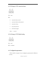
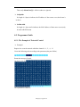
4.3.2. Order of Starting to Scan Network
FLG:0x00
PORTMASK:channel mask,the first byte represents 1~8 channels, therein Bit0
represents Channel 1,Bit1 represents Channel 2,and others calculate as this in
turn.The low 6 bits represent 9~14 channels.
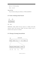
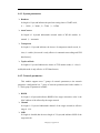
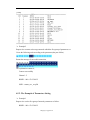
4.3.3. Message of Scanning Network Result
38th page, 55 pages in all
FLG:0x40
IDX:In the firmware of which the version is less than or equal to 1.51, it
indicates network number, and used to return the index number of result of scanning
network,the number begins from 1,each network number rises 1.
Beginning from the Version 1.53 firmware,this parameter is indicated to intension
of signal,and used to return the intension of signal of the target network,the range of
its value is 0~255, ‘0’ indicates the best intension, ‘255’ indicates the lest intension.
CH:Channel number
BSSID:BSSID of network
LEN:the length of SSID
SSID:SSID of network
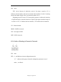
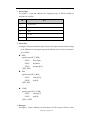
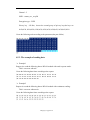
4.3.4. Order of Starting to Connect to Network
FLG:0x01
IDX:0,and indicates tolerant configuration network
1∼7,indicate which group of network configuration parameters is used
others,no defined
39th page, 55 pages in all
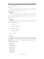
4.3.5. Message of Network Connected
FLG:0x41
RES:0,indicates connection is successful
Others,connection is failed,and the latter fields after RES are insignificant
CH:channel number
BSSID:BSSID of network
LEN:the length of SSID
SSID:SSID of network
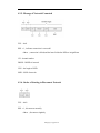
4.3.6. Order of Starting to Disconnect Network
FLG:0x02
RES:0,disconnects normally
Others,disconnect singularly
40th page, 55 pages in all
4.3.7. Message of Network Disconnected
FLG:0x42
RES:0,disconnects normally
Others,disconnect singularly
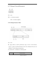
4.3.8. Setting Parameter Order
FLG:0x03
PB:group number of network parameter,the range of value is 0xb1~0xb7,they
express1~7 group of parameters.Parameter PB is choice field,this field can be not
included if it’s only setting system parameters.
M:Parameter ID,its definition is as following table.
Para ID
Parameter Meaning
41th page, 55 pages in all
0x00
Reserved
0x01
BSSID
0x02
Channel
0x03
SSID
0x04
Encryption Type
0x05
Secret Key
0x06
Data format of Link Layer
0x07
Service Port
0x08
IP address of device
0x09
IP address of server
0x0a
MAC address of server
0x0b
Subnet Mask
0x0c
IP address of gateway
0x0d
Reserved
~
0xa0
0xa1
* Serial type
0xa2
Serial paud rate
0xa3
* B/G mode
0xa4
* Tiptop speed
0xa5
* Send power
0xa6
* MAC address of device
0xa7
Networking mode
0xa8
* the degree of automatic connection after failness
0xa9
Transparent transmission mode
0xaa
TCP monitor mode
…
Reserved
(* the parameters set by the manufacturer can only be read by user)
42th page, 55 pages in all
LEN:length of INFO field
INFO:parameter content
4.3.9. Message of Setting Parameter Result
FLG:0x43
RES:0,successed
others,failed
4.3.10. Inquiring Parameter Order
FLG:0x04
PB:group number of network parameter, and its definition is same as setting
parameter order.
M:parameter ID, and its definition is same as setting parameter order
43th page, 55 pages in all
4.3.11. Message of Inquiring Result
FLG:0x44
PB:group number of network parameter
M:parameter ID,and its definition is same as setting parameter
LEN:length of INFO field
INFO:parameter content
4.3.12. Reset Order
FLG:0x05
RES:no defined
44th page, 55 pages in all
4.3.13. Message of Finished Initialization
FLG:0x45
TYP:reset type,0−hardware reset,1−software reset,others−no defined.
V:version expression,and mixed value 0x76
INFO:character strings of firmware version message
4.3.14. TCP Connection order
FLG:0x06
RES:
0 − connection is built
1 − disconnected
Other − reserved
45th page, 55 pages in all
4.3.15. Message of TCP connection Status
FLG:0x46
RES:
0 − connection has successed
1 − connection has been disconnected
2 − connection is busy
3 − not join the network
4 − orders don’t support
others − reserved
4.3.16. Message of TCP Failed Sending
FLG:0x47
RES:no defined
4.4. Configuration parameters
WLAN module can support for user configuration parameters,their definition is
as follow:
46th page, 55 pages in all
4.4.1. System parameters
Baudrate
Its length is 1 byte,and indicates the paud rate setting chose of UART serial,
0 − 19200,1−38400,2−57600,3−115200
AutoConnect
Its length is 1 byte,and indicatesthe network mode of WLAN module, 0−
manual,1−automatic.
Transparent
Its length is 1 byte,and indicates the choose of transparent transfer mode, 0−
close,1−enable(this mode is omly effective in automatic networking and UDP
data format).
TcpServerMode
Its length is 1 byte,and indicates the choose of TCP monitor mode, 0−close,1−
enable(this mode is only effective in TCP data format).
4.4.2. Network parameters
This module supports most 7 groups of network parameters,so the network
parameters configuration has 7 group of network parameters,and index number is
1~7.Each group of parameters includes:
BSSID
Its length is 6 bytes,and indicates BSSID of the target network,its value is the
MAC address of the AP used by the target network.
Channel
Its length is 1 byte,and indicatesthe channel of the target network,its effective
range is 1~14.
SSID
Its length is alterable,but the most length is 32 bytes,and indicates SSID of the
target network.
47th page, 55 pages in all
PrivacyType
Its length is 1 byte,and indicates the encryption type of WLAN module,its
definition is as follow.
值
意义
0
No Encrypted
1
WEP
2
WPI
3
CCMP
…
Reserved
PrivacyKey
Its lengh is 54 bytes,it indicates the privacy key the target network used,according
to the difference of encryption types,the definitions of privacy key framework
are as follow:
WEP
typedef struct KEY_WEP{
INT8U
KeyLength;
INT8U
KeyIndex;
INT8U
Groups[4][13];
}KEY_WEP;
WPI
typedef struct KEY_WPI{
INT8U
Unicast[32];
INT8U
pad[22];
}KEY_WPI;
CCMP
typedef struct KEY_CCMP{
INT8U
Unicast[16];
INT8U
pad[38];
}KEY_CCMP;
Datatype
Its length is 1 byte,it indicates the data format of Link Layer,its effective value
48th page, 55 pages in all
are,0−RAW,1−UDP,2 − TCP.
Port
Its length is 2 bytes,it indicates service port, the order of its bytes uses BigEndian,
namely the port number 6000 indicates 0x17,0x70.
StaIpAddr
Its length is 4 bytes,ansd indicates the IP address of WLAN module itself,the
order of its bytes uses BigEndian, namely the address 192.168.1.1 indicates 0xC0,
0xA8,0x01,0x01.
SubnetMask
Its length is 1 byte,it indicates the subnet mask of the network which WLAN
module is in,its effective value is,
0 − no setting
1 − subnet mask 255.255.255.0
2 − subnet mask 255.255.0.0
3 − subnet mask 255.0.0.0
others − reserved
SubnetGate
Its length is 4 bytes,it indicates subnet gate IP address of the network which
WLAN module is in,and its format is as above.It needs to note that ,according to the
SubnetMask value, the value of SubnetMask chooses different sffective
field,others are ignored.such as
SubnetMask=1,
SubnetGate[0]=192
SubnetGate[1]=168
SubnetGate[2]=1
SubnetGate[3]=1
49th page, 55 pages in all
Then ,only SubnetGate[3] is effective,others are ignored.
SerIpAddr
Its length is 4 bytes,it indicates the IP address of data center server,the format is
as above.
SerMacAddr
Its length is 6 bytes,and it indicates the MAC address of data center server(only
be used at RAW format).
4.5. Programme Guide
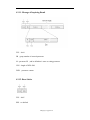
4.5.1. The Example of Network Control
Example 1
Request is to scan the network which the channel is 1、5、6、11
Create the following order according to the parameters(the part of blue).
Return the message of result,
The explaination content is,
50th page, 55 pages in all
Example 2
Request is to connect to the target network which the first group of parameters set.
Create the following order according to the parameters(the part of blue).
Return the message of successful connection,
The explaination content is,
Connect successfully
Channel:5
BSSID:00-1a-70-35-b9-32
SSID:stauart_wrv_wep128
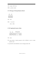
4.5.2. The Example of Parameters Setting
Example 1
Request is to set the first group of network parameters as follow:
BSSID:00-1a-70-35-b9-32
51th page, 55 pages in all
Channel:5
SSID:stauart_wrv_wep128
Encryption type:WEP
Privacy key:128 bits、choose the second group of privacy keys,the keys are
0x30,0x30, 0x30,0x30, 0x30,0x30, 0x30,0x30, 0x30,0x30, 0x30,0x30,0x30
Create the following order according to the parameters(the part of blue).
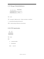
4.5.3. The example of sending data
Example 1
Request is to send the following data to WLAN module with send /response mode:
This is a test text with ack.
Create the following data frame according to the request.
Example 2
Request is to send the following data to WLAN module with continuous sending:.
This is a test text without ack.
Create the following data frame according to the request.
52th page, 55 pages in all
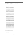
4.5.4. CRC-8 Algorithm Reference Implementation
INT8U __crc8_tbl[256]=
{
0x00,0x91,0xe3,0x72,0x07,0x96,0xe4,0x75,
0x0e,0x9f,0xed,0x7c,0x09,0x98,0xea,0x7b,
0x1c,0x8d,0xff,0x6e,0x1b,0x8a,0xf8,0x69,
0x12,0x83,0xf1,0x60,0x15,0x84,0xf6,0x67,
0x38,0xa9,0xdb,0x4a,0x3f,0xae,0xdc,0x4d,
0x36,0xa7,0xd5,0x44,0x31,0xa0,0xd2,0x43,
0x24,0xb5,0xc7,0x56,0x23,0xb2,0xc0,0x51,
0x2a,0xbb,0xc9,0x58,0x2d,0xbc,0xce,0x5f,
0x70,0xe1,0x93,0x02,0x77,0xe6,0x94,0x05,
0x7e,0xef,0x9d,0x0c,0x79,0xe8,0x9a,0x0b,
0x6c,0xfd,0x8f,0x1e,0x6b,0xfa,0x88,0x19,
0x62,0xf3,0x81,0x10,0x65,0xf4,0x86,0x17,
0x48,0xd9,0xab,0x3a,0x4f,0xde,0xac,0x3d,
0x46,0xd7,0xa5,0x34,0x41,0xd0,0xa2,0x33,
0x54,0xc5,0xb7,0x26,0x53,0xc2,0xb0,0x21,
0x5a,0xcb,0xb9,0x28,0x5d,0xcc,0xbe,0x2f,
0xe0,0x71,0x03,0x92,0xe7,0x76,0x04,0x95,
0xee,0x7f,0x0d,0x9c,0xe9,0x78,0x0a,0x9b,
0xfc,0x6d,0x1f,0x8e,0xfb,0x6a,0x18,0x89,
0xf2,0x63,0x11,0x80,0xf5,0x64,0x16,0x87,
0xd8,0x49,0x3b,0xaa,0xdf,0x4e,0x3c,0xad,
0xd6,0x47,0x35,0xa4,0xd1,0x40,0x32,0xa3,
0xc4,0x55,0x27,0xb6,0xc3,0x52,0x20,0xb1,
0xca,0x5b,0x29,0xb8,0xcd,0x5c,0x2e,0xbf,
0x90,0x01,0x73,0xe2,0x97,0x06,0x74,0xe5,
0x9e,0x0f,0x7d,0xec,0x99,0x08,0x7a,0xeb,
0x8c,0x1d,0x6f,0xfe,0x8b,0x1a,0x68,0xf9,
0x82,0x13,0x61,0xf0,0x85,0x14,0x66,0xf7,
0xa8,0x39,0x4b,0xda,0xaf,0x3e,0x4c,0xdd,
0xa6,0x37,0x45,0xd4,0xa1,0x30,0x42,0xd3,
0xb4,0x25,0x57,0xc6,0xb3,0x22,0x50,0xc1,
0xba,0x2b,0x59,0xc8,0xbd,0x2c,0x5e,0xcf
};
INT32S ChkCrc8(INT8U *ptr, INT32U len)
{
INT8U crc8,data;
crc8=0;
53th page, 55 pages in all
while(len--!=0)
{
data = *ptr++;
crc8=__crc8_tbl[crc8^data];
}
if(crc8==0x00)
return 0;
else
return -1;
}
INT8U GetCrc8(INT8U *ptr, INT32U len)
{
INT8U crc8,data;
crc8=0;
while(len--!=0)
{
data = *ptr++;
crc8=__crc8_tbl[crc8^data];
}
return crc8;
}
4.6. Modification Note of Serial Protocol
Version 1.3 modifies as follow based on version 1.0
1、The most length of LENGTH field in data format definition of UART serial
protocol modifies to 1400;
2、Data format definition of user serial protocol is increased TCP failed sending
message;
3、The definition of the IDX parameter which is the start connection order is
modified to the index number of network parameters group;
4、parameter setting order/parameter inquiry order/parameter inquiry message of user
serial protocol is increased PB field;
5、Parameter ID value M field expresses in parameter setting order/parameter inquiry
54th page, 55 pages in all
order/parameter inquiry message of user serial protocol is afresh defined.
6、The initialization completion message of user serial protocol is increased the
definition of TYP, V and INFO field;
Version 1.4 modifies as follow based on version 1.3
1、Data format definition of user serial protocol is increased TCP connection
order/status message;
2、System parameter setting is increased the TcpServerMode parameter;
Version 1.5 modifies as follow based on version 1.4
1、Network parameters configuration is increased the subnet mask and subnet gate
parameters;
2、The length of the wireless privacy key in network parameter is changed to 54
bytes from 64 bytes.
3、Beginning from Version 1.53,IDX parameter in the message of scanning network
result is modified to the denotation of network signal intension.
55th page, 55 pages in all