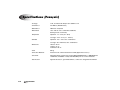
1
®
®
Infinity
Medical Image
Expansion Module
User’s Manual
Codonics® Catalog Number INFEM-MNLU
August 22, 2012
Version 1.1
Codonics, Inc.
17991 Englewood Drive
Middleburg Heights, OH 44130 USA
440-243-1198 Phone
440-243-1334 Fax
E-mail [email protected]
www.codonics.com
Copyright © 2010 – 2012 by Codonics, Inc. All rights reserved, worldwide. Printed in the
U.S.A. Part Number 905-061-101.
No part of this document may be copied or reproduced in any form by any means without
prior written consent of Codonics, Inc., 17991 Englewood Dr., Middleburg Heights, Ohio
44130 U.S.A.
Although every effort has been made to ensure the accuracy of this document, Codonics,
Inc. assumes no responsibility for any errors that may appear. Codonics, Inc. makes no
commitment to update nor to keep current the information contained in this document.
Patent Pending: All Rights Reserved.
Codonics, the Codonics logo, Infinity, and “We bring the future into focus” are registered
trademarks of Codonics, Inc.
All other registered and unregistered trademarks are the property of their respective
owners.
Contents
Preface
Conventions Used in This Manual ....................................................................................................... vii
Bulleted Lists................................................................................................................................. vii
Numbered Steps ........................................................................................................................... vii
Notes............................................................................................................................................ viii
Cautions and Warnings................................................................................................................ viii
Important Information and Filenames .......................................................................................... viii
Purpose and Scope .............................................................................................................................. ix
Product Information .............................................................................................................................. ix
Warnings and Limitations of Use .......................................................................................................... x
Safety and Compliance Label ........................................................................................................ x
Voltage Warning............................................................................................................................ xii
Dangers électriques ..................................................................................................................... xiii
Serial Number, Configuration Number, Date Code, and Modification Codes ............................... xv
Potential for Radio Frequency Interference on Device Operation................................................ xvi
Potential for Radio and Television Interference ........................................................................... xvi
Safety Precautions ....................................................................................................................... xvi
Précaution d’Emploi .................................................................................................................... xvii
Location Precautions.................................................................................................................. xviii
Environnement de Fonctionnement .............................................................................................. xx
Cleaning Precautions .................................................................................................................. xxii
Codonics Infinity Expansion Module User’s Manual
iii
Précautions d’Entretien ............................................................................................................... xxii
Maintenance Precaution ............................................................................................................ xxiii
Précaution d’Entretien................................................................................................................ xxiii
Disposal Requirements .................................................................................................................... xxiv
Conditions et Règles d’Utilisation............................................................................................... xxiv
European Disposal Requirements ............................................................................................. xxiv
Indications for Use ............................................................................................................................. xxv
Chapter 1: Introduction
Welcome and Congratulations .......................................................................................................... 1-1
Product Features ............................................................................................................................... 1-2
Chapter 2: Setting Up the Expansion Module
Finding a Location ............................................................................................................................. 2-1
Components ...................................................................................................................................... 2-3
Unpacked Components............................................................................................................... 2-3
Infinity Expansion Module Front Components ............................................................................ 2-5
Infinity Expansion Module Rear Components ............................................................................. 2-6
Installing Infinity Software .................................................................................................................. 2-7
Adding the Expansion Feature Key ................................................................................................... 2-8
Installing the Hardware .................................................................................................................... 2-14
Starting Up the Infinity System ........................................................................................................ 2-22
Shutting Down and Rebooting ......................................................................................................... 2-24
iv
Contents
Chapter 3: Maintenance
Cleaning the Enclosure ..................................................................................................................... 3-1
Replacement Procedures .................................................................................................................. 3-2
Replacing a Hard Drive ............................................................................................................... 3-2
Replacing the AC Power Adapter ............................................................................................. 3-10
Replacing the Expansion Module Chassis................................................................................ 3-13
Ordering Parts ................................................................................................................................. 3-22
Preparing for Shipping ..................................................................................................................... 3-22
Chapter 4: Status Indicators and Troubleshooting
Front Panel Status Lights .................................................................................................................. 4-2
System Status User Interface ............................................................................................................ 4-4
Status Indicators ......................................................................................................................... 4-6
Navigating Detailed Status Information....................................................................................... 4-9
Detailed Status in Information Panels ....................................................................................... 4-11
Troubleshooting Common Problems ............................................................................................... 4-13
Appendix A: Hazardous Material Information
Materials of Construction ................................................................................................................... A-1
Matériaux de Construction .......................................................................................................... A-2
Manufacturing .................................................................................................................................... A-3
Fabrication .................................................................................................................................. A-3
Codonics Infinity Expansion Module User’s Manual
v
Appendix B: Specifications
Specifications (English) ..................................................................................................................... B-1
Spécifications (Français) ................................................................................................................... B-2
Index
vi
Contents
Preface
Conventions Used in This Manual
Bulleted Lists
Bullets are used to display a list of nonprocedural items. For example:
When finding a suitable location for the Infinity Expansion Module, use the following
guidelines:
•
Do not block ventilation on the front, rear, top, bottom, and sides of the Infinity
Expansion Module.
•
Make sure that the countertop or work surface will not vibrate or shake when the
Infinity Expansion Module is operating.
Numbered Steps
8
The
icon indicates the beginning of a procedure. The steps in a procedure are
numbered. For example:
8
To replace the
chassis
1. Unpack the Infinity Expansion Module replacement chassis.
2. Place the replacement chassis on a flat, solid surface near the original chassis.
3. Remove the tape securing the front cover.
Codonics Infinity Expansion Module User’s Manual
vii
Notes
Notes contain additional information related to a topic or procedure. For example:
3
NOTE: This will power up the main chassis and all expansion modules.
Cautions and Warnings
Cautions alert you to actions or situations that could cause harm to equipment or data.
For example:
CAUTION Only trained users should install and configure the system.
Warnings alert you to actions or situations that could result in personal injury. For
example:
WARNING Grounding reliability can be achieved only when the Infinity Expansion Module or any
externally powered accessory (UPS) is connected to an equivalent receptacle marked “Hospital Only”
(that is, “Hospital Grade”).
Important Information and Filenames
Bold type is used for emphasis, command names, and paths or filenames. For example:
• When you have completed entering the system configuration parameters, click the
Save button and close the window.
• In Windows, navigate to and run the Configurator.exe file, which is stored at the root
level of the SmartDrive.
viii
Preface
Purpose and Scope
Refer to this User’s Manual for procedures on how to perform the Infinity Expansion
Module user operations, including:
• Setting up the hardware and software
• Maintaining the Infinity Expansion Module
• Monitoring system status and troubleshooting common problems
Product Information
For technical assistance with the Infinity Expansion Module, call Codonics Technical
Support at the following number:
Phone:
Toll Free:
+1-440-243-1198
800-444-1198 (USA only)
Codonics Customer Service is available weekdays from 8:30 AM to 5:30 PM EST (U.S.
holidays excluded). Technical Support is also available online via e-mail and the Codonics
web site:
E-mail:
Web site:
[email protected]
www.codonics.com
General product information can also be requested by sending e-mail to:
E-mail:
[email protected]
Codonics Infinity Expansion Module User’s Manual
ix
Please include your postal mailing address and telephone number in the e-mail message.
Basic product information is returned via e-mail. Complete product literature is sent by
postal mail.
Warnings and Limitations of Use
Safety and Compliance Label
The product is in compliance with various regulations, details of which are listed in
Appendix B.
The Infinity Expansion Module safety and compliance label is located on the left side of
the chassis (shown on the following page).
x
Preface
This product satisfies the Class B limits of
EN 60601-1-2 and CISPR 11.
Infinity Medical Image
Expansion Module
Made in the U.S.A.
All Rights Reserved
Safety and compliance
label location
ETL CLASSIFIED
CONFORMS TO
UL STD 60601-1
CERTIFIED TO
CAN/CSA STD C22.2 NO. 601.1
3125782
MODEL / MODELE
INFINITY-2X
Infinity Expansion Module safety and compliance label, located on left side of chassis
Codonics Infinity Expansion Module User’s Manual
xi
Voltage Warning
The exclamation point within a triangle is intended to alert the user to the presence of
important operating and maintenance (servicing) instructions in the literature
accompanying this device.
REFER SERVICING TO QUALIFIED SERVICE PERSONNEL. REMOVAL OF LABELS,
COVERS, OR ENCASEMENT FASTENERS MAY VOID THE WARRANTY.
THIS APPARATUS MUST BE ELECTRICALLY GROUNDED.
TO PREVENT FIRE OR SHOCK HAZARD, DO NOT EXPOSE THIS DEVICE TO RAIN OR
MOISTURE.
EQUIPMENT IS NOT TO BE USED AS A COMPONENT OF A LIFE SUPPORT SYSTEM.
Life support devices or systems are devices or systems that support or sustain life, and
whose failure to perform can be reasonably expected to result in a significant injury or
death to a person. A critical component is any component of a life support device or
system whose failure to perform can be reasonably expected to cause the failure of the
life support device or system, or to affect its safety or effectiveness.
WARNING The power cord plugs at the rear panels of the main chassis and expansion modules are the
main disconnects for the Infinity system.
WARNING To disconnect power to the Infinity Expansion Module prior to servicing it, shut down the
system (refer to “Shutting Down and Rebooting” on page 2-24) and then disconnect the power cord plug
at the rear panel of the module.
xii
Preface
WARNING Grounding reliability can be achieved only when the Infinity Expansion Module or any
externally powered accessory (UPS) is connected to an equivalent receptacle marked “Hospital Only”
(that is, “Hospital Grade”).
WARNING External equipment intended for connection to signal input, signal output, or other
connectors, shall comply with relevant IEC standard (e.g., IEC 60950 for IT equipment and the IEC 60601
series for medical equipment). In addition, all such combinations - systems - shall comply with the IEC
60601-1-1 standard, safety requirements for medical electrical systems. Equipment not complying to IEC
60601 shall be kept outside the patient environment, as defined in the standard. Any person who connects
external equipment to signal input, signal output, or other connectors has formed a system and is
therefore responsible for the system to comply with the requirements of IEC 60601-1-1. If in doubt, contact
a qualified technician or Codonics Technical Support for approved configurations.
Dangers Électriques
Le point d'exclamation situé à l'intérieur d'un triangle équilatéral représente un point
d'instruction important dans l'utilisation de cette appareil.
ADRESSEZ-VOUS AU PERSONNEL QUALIFIE. LE FAIT DE RETIRER LES ETIQUETTES OU DE
DEMONTER LE COVERCLE ANNULENT LA GARANTIE.
CET APPAREIL DOIT ETRE RELIE A LA TERRE.
N’EXPOSEZ PAS CET APPAREIL À LA PLUIE OU L’HUMIDITÉ, EN RAISON DU RISQUE DE
FEU OU DE DÉCHARGES ÉLECTRIQUES.
Codonics Infinity Expansion Module User’s Manual
xiii
Cet appareil ne doit pas être utilisé comme composant d’un système d'assistance vitale. Cet
appareil ne doit pas être utilisé dans des conditions où la défaillance de l’appareil
pourrait entrainer blessure ou mort d’homme.
ATTENTION Les fiches d'alimentation à l'arrière de l'appareil et les extensions de mémoire sont le
système principal de coupure de l'appareil.
ATTENTION Avant d'intervenir sur l'extension de mémoire Infinity, veuillez à toujours l'arrêter (veuillez
référer à “Shutting Down and Rebooting” on page 2-24) et n'oublier de débrancher le fiche d'alimentation
à l'arrière de la machine.
ATTENTION Une mise à la terre fiable est possible seulement pendant quel'Infinity ou l'accessoire
d'alimentation externe (UPS) est relié aux appareils aussi “ Hospital Only “ (de qualité hospitalière).
ATTENTION Toute intention de connections externe d'equipement vers le signal d'entrée ou de sortie ou
autre connecteur, doit être compatible avec la norme IEC standard (IEC 60950 pour les équipements IT et
IEC 60601 pour les équipements médicaux).Tout les combinaisons de systèmes doivent être compatible
avec IEC60601-1-1- standard, sécurité requise pour les équipements électriques médicaux.
Tout équipement non compatible avec IEC 60601 doit être mis a l'écart de l'environnement patient, comme
définis dans le standard.Toute personne qui connecte un équipement externe vers une entrée signal, ou
sortie signal ou autres connecteur, est responsable de la compatibilité avec IEC 60601-1-1.Si vous avez
un doute,contacter un technicien qualifie ou le support technique de Codonics pour l'approbation des
configurations.
xiv
Preface
Serial Number, Configuration Number, Date Code, and
Modification Codes
The serial number, configuration number, date code, and modification codes are located
on the safety and compliance label, which is on the left side of the chassis.
• The serial number (SN) uniquely identifies the unit.
• The configuration number (CN) details the build configuration.
• The modification codes are to the right of the CN number and are a series of 20
numbers. When any of these numbers are blocked out, that identifies a modification
that was made to the unit.
• The date code is in YYYY-MM format below the factory date code symbol.
Serial number
Configuration
number
Date code
Modification
codes
Serial number, configuration number, date code, and modification codes
Codonics Infinity Expansion Module User’s Manual
xv
Potential for Radio Frequency Interference on Device
Operation
Both portable and mobile RF communications equipment can affect medical electrical
equipment, including the Codonics Infinity Expansion Module. Keep such RF
communications equipment out of the immediate area.
Potential for Radio and Television Interference
This product is in conformity with the protection requirements of EC Council directive
89/336/EEC on the approximation of the laws of the Member States relating to
electromagnetic compatibility. This product satisfies the Class B limits of EN55011. A
declaration of conformity with the requirements of the Directive has been signed by the
Director of Quality Assurance and Regulatory Affairs.
Safety Precautions
• Never connect the Infinity Expansion Module power adapter to any outlet or power
supply that has a voltage or frequency different than that specified (100 – 240 VAC,
50/60 Hz).
• Use only the external AC power adapter provided with the Infinity Expansion Module
(Codonics part number SP-00448).
• When replacing the chassis, always shut down the Infinity system (refer to “Shutting
Down and Rebooting” on page 2-24) and disconnect the AC power cords from the
main chassis and any expansion modules prior to servicing it.
• Damage to a power cord is a fire and shock hazard. When unplugging a power cord,
hold it by the plug only and remove the plug carefully.
xvi
Preface
• If a power cord or power adapter needs to be replaced, replace it only with another
Codonics power cord or Codonics power adapter. Alternatively, replace it with a power
cord or power adapter manufactured specifically for your power configuration.
• If the device is smoking or making unusual sounds, power off and unplug the device
immediately (refer to “Shutting Down and Rebooting” on page 2-24).
• Do not insert foreign objects of any kind into the device; doing so can constitute a
safety hazard and cause extensive damage.
• Do not place any liquid containers on the device. If, for some reason, liquid seeps into
the device, power off the device and unplug the power cord from the source outlet. If
used without taking corrective measures, the device may be damaged.
• Do not use the device near flammable gases.
Précaution d’Emploi
• Ne jamais brancher cet appareil sur une source d’alimentation électrique dont la
tension ou la fréquence diffèrent des valeurs indiquées (100 – 240 VAC, 50/60 Hz).
• Utiliser uniquement le bloc d’alimentation fourni avec l’appareil (numero de piéce
Codonics SP-00448).
• Avant de remplacer le bloc d’alimentation ou le châssis principal, veuillez à toujours
éteindre l’appareil puis l’interrupteur situé à l’arrière et enfin, n’oubliez pas de
débrancher le câble secteur.
• Un cordon d’alimentation endommagé est une cause d’incendie ou de décharge
électrique. En déconnectant le cordon d’alimentation, tenez-le seulement par la prise
et retirez la prise soigneusement.
• Si le cordon d'alimentation ou le bloc d'alimentation doit être remplacé, utilisez un
cordon d'alimentation ou un bloc d'alimentation Codonics fabriqué spécifiquement
pour votre appareil.
Codonics Infinity Expansion Module User’s Manual
xvii
• Si l’appareil fume ou émet des bruits inhabituels arrêtez-le immédiatement et
débranchez le câble secteur.
• N’introduisez aucun objet étranger dans l’appareil, cela peut être une source de danger
et peut causer de graves dommages.
• Ne déposez aucun récipient à coté de l’appareil. Si pour une raison quelconque un
liquide est renversé à l’intérieur, arrêtez immédiatement l’appareil et débranchez le
câble secteur. Toute nouvelle utilisation de l’appareil sans intervention peut causer de
graves dommages.
• Ne pas utiliser l’appareil à coté d’une source de gaz inflammable.
Location Precautions
• The device’s operating ambient temperature range is 15–30ºC
(59–86ºF), with a relative humidity of 20%–80%.
• If the device is moved quickly from an extremely cold place to a warmer one,
condensation is likely to form. Do not use the device if condensation has formed. Wait
until the condensation has evaporated. You can speed up the evaporation time by
moving the device to a drier location.
• Ventilation slots and holes are provided on the front, rear, top, bottom, and sides of
the device. Place the device on a level, stable surface and locate it at least 5 cm (2 in.)
between chassis and other chassis or wall to ensure proper ventilation.
• Do not stack the main chassis and/or expansion modules on top of one another.
CAUTION Adequate ventilation is required for proper operation of the device.
xviii
Preface
• When installed with a UPS, the system should not be located in patient care
environments unless the UPS used or an appropriate isolation device meets local
regulatory requirements.
WARNING Grounding reliability can be achieved only when the Infinity system or its uninterruptable
power supply (UPS) is connected to an equivalent receptacle marked “Hospital Only” (that is, “Hospital
Grade”).
WARNING Customers should consider using an appropriate isolation transformer or a medical grade
UPS in environments that require less than 300 μA chassis leakage. Please check local/regional and
hospital-specific ordinances to determine the applicability of any/all standards based on the intended use
and placement of the Infinity system.
• Do not place objects on top of the device.
• Do not place device in a high humidity or high dust area. Airborne dirt particles can
cause interference with the operation of the device. Avoid placing the device in areas
where ventilation ducts, open doors, or frequent passers-by might expose the device
to high levels of debris.
• Do not locate the device in hot-springs areas where hydrogen sulfide and acidic ions
are likely to be generated.
• Do not locate the device where there are oily fumes and vapors.
• Do not locate device near sources of high RF energy, high magnetic fields, or ionizing
radiation.
• Do not place the Infinity Expansion Module near heat sources such as radiators or air
ducts, or in a location subject to direct sunlight, excessive dust, mechanical vibration,
or shock.
Codonics Infinity Expansion Module User’s Manual
xix
• Make sure that the countertop or work surface will not vibrate or shake when the
Infinity Expansion Module is operating.
Environnement de Fonctionnement
• Les conditions normales d’utilisation de l’appareil sont : une température de 15 à 30ºC
(59 à 86ºF) et une humidité relative
de 20 % à 80 %.
• Une variation rapide de température risque de provoquer de la condensation. Dans ce
cas n’utilisez pas l’appareil, attendre la condensation se soit évaporée. Vous pouvez
accélérer cette évaporation en déplacant l’appareil dans un endroit sec.
• Les fentes de ventilation se trouvent à l’avant et à l’arrière de l’appareil. Placez
l’appareil sur une surface stable et au moins 5 cm (2 in.) des murs et d’autres objets
pour assurer une ventilation correcte.
• Ne placez pas le châssis principal et/ou des appareils d’expansion, l’un sur l’autre.
ATTENTION Une ventilation correcte est nécessaire au bon fonctionnement de l’appareil.
• En installation avec un onduleur (UPS), le système doit être mis à l’écart de
l'environnement patient sauf en connexion avec un UPS ou un transformateur
d’isolement qui respecte les ordonnances spécifiques locale/régionale.
ATTENTION Une mise à la terre fiable est possible seulement pendant que Infinity ou son onduleur (UPS)
s'est connecté aux appareils marqué “Hospital Only” (de qualité hositalière).
xx
Preface
ATTENTION L’utilisateur doit considérer l’utilisation d’un transformateur d’isolement ou un UPS médical
dans un environnement qui nécessite un courant de fuite de moins de 300 μA. Merci de vérifier les
ordonnance spécifiques locale/régionale et hôpitaux afin de déterminer l’application de n'importe
quel/touts standard lie au placement et a l'utilisation du produit Infinity.
• Ne pas poser d’objets sur l’appareil. Ils risquent de bloquer la ventilation ou de fendre
le couvercle.
• Ne placez pas l’appareil dans une zone propre et non-humide. Des particules de
poussières peuvent causer des disfonctionnements. Évitez de placer l’appareil à
proximité d’une bouche de ventilation, d’une porte, ou d’un lieu très fréquenté car cela
pourrait exposer l’appareil à la poussière.
• Ne placez pas l’appareil à proximité d’une source de chaleur ou de substances acides.
• Ne placez pas l’appareil dans une pièce où il y a des vapeurs huileuses et grasses.
• Ne placez pas l’appareil près des sources d'énergie RF, des champs hauts-magnetiques,
ou du rayonnement ionisant.
• Ne placez pas l’appareil d'expansion à proximité des sources de chaleur comme des
radiateurs ou des conduits d'air. A proteger contre les rayons solaires, du poussière et
des vibrations méchaniques.
• Assurez-vous que le plan de travail soit calme pendant que l’appareil d'expansion est
allumé.
Codonics Infinity Expansion Module User’s Manual
xxi
Cleaning Precautions
• Plastic components are used in the device’s construction. Coat flecking and
deformation are likely to occur if the device is wiped with chemical dusters, benzene,
thinners, insecticides, or other solvents. Rubber and PVC materials left in contact with
the device for extended times will cause damage. Never use petroleum-based solutions
or abrasive cleaners.
• To clean the chassis enclosure, first shutdown and disconnect power to the Infinity
main chassis and any expansion modules (refer to “Shutting Down and Rebooting” on
page 2-24). Clean the enclosure with a soft cloth slightly moistened with a mild soap
and water solution. Allow the enclosure to completely dry before operating the device
again.
Précautions d’Entretien
• Cet appareil comporte plusieurs pièces en plastique. Des taches et des déformations
peuvent être provoquées par l’utilisation de chiffon imbibé de benzène, d’essences,
d’insecticides, ou d’autres solvants. N’utilisez jamais solution à base de pétrole.
• Pour nettoyer le baie de châssis, veuillez l’éteindre et débrancher le cordon
d’alimentation pour l’Infinity et tous les appareils d’expansion (voir sur “Shutting
Down and Rebooting” on page 2-24). Nettoyez la baie avec un tissu doux légèrement
humidifié avec une solution à base d’eau et de savon non corrosif. Laissez sécher avant
de remettre en fonction le système.
xxii
Preface
Maintenance Precaution
The Infinity Expansion Module includes a robust user warning system to decrease the
likelihood of permanent data loss. It is imperative that users act to prevent permanent
data loss when the Infinity Expansion Module indicates that there is a problem. Failure
to do so may invalidate the system warranty and will jeopardize system data.
Précaution d’Entretien
L’appareil the Infinity Expansion Module comprend un système d'utilisateur renforcé
avec des avertissements afin de réduire le risque de la perte des données. L’inactivité en
cas d'avertissement risque d’endommager la base de données.
Codonics Infinity Expansion Module User’s Manual
xxiii
Disposal Requirements
Disposal of this product and consumables shall be in accordance with all applicable laws
and regulations in effect at the locality at the time of disposal. For additional information,
refer to Appendix A, Hazardous Material Information.
Conditions et Règles d’Utilisation
L’utilisation de ce produit doit être conforme à toutes les lois et règlements applicables sur
le lieu d’utilisation.
European Disposal Requirements
Codonics products and electronic accessory devices are not to be discarded or recycled;
rather they are to be returned to the manufacturer. Contact Codonics directly or by the email link provided for the latest information concerning:
• Identification of the country-specific Importer/Distributor/Producer
• Product return and treatment of our electronic products
Manufacturer: Codonics Incorporated
17991 Englewood Drive
Middleburg Heights, OH 44130 USA
Phone: +1-440-243-1198
Fax: +1-440-243-1334
E-mail: [email protected]
www.codonics.com/weee
xxiv
Preface
Codonics products and electronic accessory devices bearing the following symbol are
subject to European Directive on Waste Electrical and Electronic Equipment (WEEE)
2002/96/EC, amended by Directive 2003/108/EC. The EN 50419 symbol indicates
separate collection and return required.
EN 50419 symbol
Indications for Use
The Infinity Expansion Module is an accessory that provides storage expansion for the
Infinity Medical Image Server. The Infinity Series of Medical Image Servers are Class 1
FDA 892.2020 medical image communications and storage appliances. The Infinity
product integrates software and server hardware to provide DICOM digital images and
data storage and retrieval from various sources including but not limited to CT, MR, US,
NM/PET, CR/DR, secondary capture, film digitizers, workstations, and import gateways.
Data can be stored, managed, and forwarded via software provided on the appliance,
including non-diagnostic review/management of images on the server, and via optional
web-enabled JPEG and web DICOM image delivery.
Codonics Infinity Expansion Module User’s Manual
xxv
Users of this system are trained medical professionals, including but not limited to
physicians, nurses, and radiological technicians. Those users responsible for the setup,
operation, and maintenance of the system may include radiology technologists, PACS
administrators and IT personnel. Primary applications include temporary and quarantine
storage of large DICOM data sets directly from any modality and permanent storage of
digital images in a pre-PACS environment with security and transaction logs to support
patient confidentiality audit compliance.
xxvi
Preface
1
Introduction
Welcome and Congratulations
Congratulations on your purchase of the Codonics® Infinity® Expansion Module!
Codonics Infinity Expansion Module User’s Manual
1-1
We are pleased you chose the Infinity Expansion Module. We are confident that it will
provide fast, reliable storage of medical images for your demanding data storage and
distribution applications.
Product Features
The Infinity system is a DICOM storage device that provides a simple solution for storing
and retrieving medical images. Applications such as direct modality storage of large
DICOM data sets or storage of digital images in an environment without a centralized
image server are ideal for an Infinity system.
Three Infinity Expansion Modules, each with up to four hard drives, can be connected to
an Infinity main chassis, providing up to 9 TB of additional storage.
The expansion module is easily connected to the Infinity main chassis and to other
expansion modules using a single SAS [Serial Attached SCSI (Small Computer System
Interface)] cable.
1-2
Introduction
2
Setting Up the Expansion
Module
Finding a Location
When finding a suitable location for the Infinity Expansion Module, use the following
guidelines:
•
Place the Infinity Expansion Module on a flat, hard surface and in a location with
adequate air circulation to prevent internal heat build up.
•
Place the Infinity Expansion Module close enough to the Infinity main chassis or
expansion module to which it will be connected so that the SAS cable can be
connected between the two devices.
Codonics Infinity Expansion Module User’s Manual
2-1
•
Do not place the Infinity Expansion Module near heat sources such as radiators or air
ducts, or in a location subject to direct sunlight, excessive dust, mechanical vibration,
or shock.
•
Do not block ventilation on the front, rear, top, bottom, or sides of the Infinity
Expansion Module.
•
Make sure that the countertop or work surface will not vibrate or shake when the
Infinity Expansion Module is operating.
For additional location precautions, refer to “Location Precautions” on page xviii.
2-2
Setting Up the Expansion Module
Components
Unpacked Components
The Infinity Expansion Module is shipped in one carton and contains the components
shown in the following illustration.
Expansion
module
AC power adapter
1
2
!
1
AC power cord
Key
1
2
!
Expansion module
numbered labels
1 2 3
Documentation
SAS cable
Software Installation
and User’s Manual discs
Unpacked Infinity Expansion Module components
Codonics Infinity Expansion Module User’s Manual
2-3
Inspect the carton for damage that might have occurred during shipping. Report any
damage to the shipping company.
Save the carton and packing materials, in case you ever need to transport the Infinity
Expansion Module later.
2-4
Setting Up the Expansion Module
Infinity Expansion Module Front Components
The following illustration is provided for reference as you perform the installation tasks
in this chapter. It shows the components at the front of the Infinity Expansion Module,
with the hard drives installed.
Hard drives
Use Only
CodonicsParts
Removing more than
one hard drive may cause
permanent data loss.
Contact technical
support before servicing.
Failure to comply may
void warranty.
Power button on Main
Chassis controls power
for all Expansion Modules.
Front door
1
1
2
3
4
Status lights
2
3
Expansion ON
Infinity Expansion Module front panel components
•
Opening the Front door provides access to the front panel components.
•
The Status lights indicate Expansion status.
•
The Hard drives are housed in the hard drive slots.
Codonics Infinity Expansion Module User’s Manual
2-5
Infinity Expansion Module Rear Components
OUT
The following illustration is provided for reference as you perform the installation tasks
in this chapter. It shows the input/output ports at the rear of the Infinity Expansion
Module.
IN
SAS
connectors
Infinity Expansion Module rear panel components
2-6
Setting Up the Expansion Module
Power
connector
Installing Infinity Software
To support expansion modules, the Infinity software must be at v1.4.0 or later. If you
have to upgrade the Infinity software, use the following general procedure.
CAUTION Only trained users should install the system software.
CAUTION The Infinity system is designed to run only authorized Infinity software. Do not install other software
applications. This includes unauthorized anti-virus software. Installation of unauthorized software applications can
affect system performance or interfere with system operation.
CAUTION Do not perform a full Infinity software installation or reinstallation unless directed to do so by Codonics
Technical Support (+1 440-243-1198). A full installation removes all files, including all Windows files, all Infinity
application files (except the Infinity configuration files), and the studies database.
8
To install
Infinity
software
1. Load the Operating Software disc in the disc drive on the front panel of the main
chassis.
2. Reboot the Infinity system, as described in “Shutting Down and Rebooting” on
page 2-24.
After rebooting, software installation begins. The Operating System disc will eject
after approximately 20 minutes.
3. Wait 30 to 60 minutes for the installation to complete.
Six audible beeps indicate when software installation is complete, and the Infinity
user interface will be accessible remotely.
Codonics Infinity Expansion Module User’s Manual
2-7
Adding the Expansion Feature Key
Before using the Infinity Expansion Module for the first time, the Expansion Module
feature key must be added to the system configuration on the main chassis SmartDrive.
If you do not have the feature key for your expansion module, contact Codonics Technical
Support (+1 440-243-1198) for the key.
CAUTION Only trained users should configure the system.
CAUTION Do not reconfigure or modify the software except as described in configuration tasks documented in
this manual.
8
To add the
Expansion
Module
feature key
2-8
1. Remove the SmartDrive from the main chassis and insert it to a USB port on a PC.
The SmartDrive will appear as a standard USB flash drive.
Setting Up the Expansion Module
2. In Windows, navigate to and run the Configurator.exe file, which is stored at the root
level of the SmartDrive.
Configurator.exe
The Configurator application opens.
Codonics Infinity Expansion Module User’s Manual
2-9
3. Click the Advanced tab.
Advanced tab
2-10
Setting Up the Expansion Module
4. Click the Feature Keys subtab.
Add New Feature subtab
5. Click the Add button.
Codonics Infinity Expansion Module User’s Manual
2-11
6. The Add New Feature dialog box displays.
7. Enter the Expansion Module feature key.
8. Click the OK button.
9. Make any other configuration changes that might be needed. For more information
about the other configuration settings, refer to the Infinity User’s Manual or Reference
Guide.
10. When you have completed entering the system configuration parameters, click the
Save button and close the window.
11. Unmount and remove the SmartDrive from the PC.
2-12
Setting Up the Expansion Module
HDMI
DVI
12. Insert the SmartDrive into its USB port on the Infinity main chassis (the USB port at
the rear of an Infinity C is shown below).
Codonics Infinity Expansion Module User’s Manual
2-13
Installing the Hardware
CAUTION Only trained users should install and configure the system.
3
8
To install the
hardware
NOTE: Infinity software version 1.4.0 or later must be installed on the Infinity main chassis before installing the expansion
module hardware. For more information, refer to “Installing Infinity Software” on page 2-7. Also, the Expansion Module
feature key must be added; refer to “Adding the Expansion Feature Key” on page 2-8.
1. Shut down the Infinity system (refer to “Shutting Down and Rebooting” on
page 2-24).
2. Unpack the hardware and remove any packing material.
3. Place the Infinity Expansion Module on a solid level surface.
2-14
Setting Up the Expansion Module
IN
OUT
4. Connect the power cord from the AC adapter.
3
NOTE: The power cord plug at the rear panel of the chassis is the main disconnect for the Infinity Expansion Module.
Codonics Infinity Expansion Module User’s Manual
2-15
5. Secure the power cord with the attached retaining clip.
Retaining clip
6. Connect the AC power cord to the AC adapter.
3
2-16
NOTE: It is highly recommended that a UPS be used with the Infinity Expansion Module.
Setting Up the Expansion Module
7. If not using a UPS, connect the AC power cord to a wall outlet (shown above).
CAUTION When installing the Infinity Expansion Module as part of a system such as the Infinity Medical Image
Server, all attached system components must be connected to the same AC line power circuit.
CAUTION A UPS is highly recommended to reduce the risk of data loss due to power failures. An EN60950 UPS
is not suitable for installation in a patient care area. Please check local/regional and hospital-specific ordinances
to determine the applicability of any/all standards based on the intended use and placement of the Infinity system.
If not using a UPS, a multiple portable socket outlet (MPSO) can be used for powering
the system.
WARNING Use of MPSOs to connect the equipment to the power outlet must be used as specified in IEC
60601-1-1. MPSOs used within the U.S. must contain “Hospital Grade” outlet sockets and be fitted with a
Mains plug marked as being “Hospital Grade.”
WARNING When using an MPSO, do not connect items that are not specified as part of the system. An
additional MPSO or extension cord must not be connected to the system.
WARNING MPSOs must not be placed on the floor.
WARNING An MPSO’s maximum permitted load must exceed 1000 VA.
Codonics Infinity Expansion Module User’s Manual
2-17
If using a UPS, connect the AC power cord to the UPS (shown below).
CAUTION Connect the Infinity Expansion Module to only high-quality electrical power. Do not expose the Infinity
Expansion Module to suboptimal power conditions, including but not limited to power spikes or over- or undervoltage conditions.
WARNING To disconnect overall power to the Infinity Expansion Module prior to servicing it, shut down
the system (refer to “Shutting Down and Rebooting” on page 2-24) and then disconnect the power cord
plug at the rear panel of the chassis.
2-18
Setting Up the Expansion Module
8. Connect the expansion module’s SAS cable(s).
IN
HDMI
DVI
OUT
When connecting a SAS cable between the main chassis and the first expansion
module in a chain, the cable connects to the main chassis’ SAS connector and to the
first expansion module’s SAS IN connector, as shown in the following illustration.
Codonics Infinity Expansion Module User’s Manual
2-19
OUT
OUT
OUT
IN
IN
IN
HDMI
DVI
When connecting a SAS cable between expansion modules in the chain, the cable
connects to the previous module’s SAS OUT connector and the next module’s SAS IN
connector, as shown in the following illustration.
CAUTION Properly connect the SAS cables. Make sure that they are secure. Do not disconnect a SAS cable
during system operation, as data could be lost.
9. Start up the Infinity system (refer to “Starting Up the Infinity System” on page 2-22).
10. Observe the expansion module identification lights on the expansion module front
panel. This will indicate which number has been permanently assigned to the
expansion module.
3
2-20
NOTE: Expansion module 1 powers on about one minute after the main chassis has powered on. The other expansion
modules in the chain power on in sequence according to their assigned module number.
Setting Up the Expansion Module
If the system includes multiple expansion modules, you might want to rearrange the
expansion modules so that their physical order matches their assigned numbers.
Power button on Main
Chassis controls power
for all Expansion Modules.
1
Expansion module
identification lights
2
3
Expansion ON
11. Once you know the expansion module’s assigned number, remove the appropriate
number label from the Infinity Expansion Module numbers sticker and apply it to the
nameplate on the front door.
Number label
Codonics Infinity Expansion Module User’s Manual
2-21
Starting Up the Infinity System
3
8
NOTE: The main chassis controls power to the expansion modules.
1. If a monitor is installed, press the monitor power button.
To start up the
Infinity system
Power button
2. If there is a UPS, power on the UPS.
2-22
Setting Up the Expansion Module
3. Momentarily press the Power button at the front of the Infinity main chassis (the
Infinity C Power button is shown below).
1
2
Power button
!
This will power up the main chassis and all expansion modules.
3
NOTE: Expansion module 1 powers on about one minute after the main chassis has powered on. The other expansion
modules in the chain power on in sequence according to their assigned module number.
4. Wait approximately 5 minutes for startup to complete.
Codonics Infinity Expansion Module User’s Manual
2-23
Shutting Down and Rebooting
Use the following procedure to shut down or reboot the Infinity system from a Remote
Desktop Connection or from a monitor, keyboard, and mouse connected directly to the
Infinity main chassis.
3
8
To shut down
or reboot the
system
NOTE: The main chassis controls power to the expansion modules.
1. Before attempting to shut down or reboot the system, make sure that all jobs have
finished and all applications (for example, the Administration tool or Study Manager)
are closed.
2. On the Start menu, click System Shutdown.
Click System Shutdown
2-24
Setting Up the Expansion Module
You are prompted to confirm the shutdown.
3. Click the Shutdown or Reboot button.
Click Shutdown or
Reboot
Codonics Infinity Expansion Module User’s Manual
2-25
The Power lights at the front of the main chassis and any expansion modules turn off
when shutdown is complete.
Main chassis
Power light
1
2
!
Power button on Main
Chassis controls power
for all Expansion Modules.
1
2
3
Expansion ON
Expansion module
Power light
2-26
Setting Up the Expansion Module
3
Maintenance
Cleaning the Enclosure
To clean the Infinity Expansion Module enclosure, log out, and shut down the system
(refer to “Shutting Down and Rebooting” on page 2-24). When it is powered off, unplug
the Infinity Expansion Module power cord.
Clean the enclosure with a clean soft cloth or towel slightly moistened with a mild soap
and water solution. Allow the enclosure to completely dry before operating the Infinity
Expansion Module again.
CAUTION Always power off the Infinity Expansion Module and disconnect its power cord before cleaning.
Resume operation only after the surfaces are completely dry.
Codonics Infinity Expansion Module User’s Manual
3-1
Replacement Procedures
CAUTION The Infinity system includes a robust user warning system to decrease the likelihood of permanent
data loss. It is imperative that users act to prevent permanent data loss when the Infinity system indicates that
there is a problem. Failure to do so may invalidate the system warranty and will jeopardize system data.
Replacing a Hard Drive
If a hard drive fails, it should be replaced immediately.
CAUTION Do not remove more than one hard drive at a time. This could cause permanent data loss. Failure to
comply with this caution may void the Infinity Expansion Module warranty.
CAUTION To avoid data loss, make sure that you are replacing the failed drive. To identify the failed drive, the
drive’s status light will be red.
8
To replace a
failed hard
drive
3-2
1. Do not shut down the Infinity system.
2. Open the expansion module door.
Maintenance
3. Make sure that you properly identify the failed hard drive. Its activity light will be red.
U
Cod
Remo
one har
perma
Con
support
Failure
vo
Power
Chass
for all Ex
1
Hard drive
activity light
Codonics Infinity Expansion Module User’s Manual
3-3
If you cannot find the hard drive with a red activity light, use the System Status user
interface to locate the failed hard drive.
Location of
failed drive
CAUTION If it is not apparent which hard drive has failed, DO NOT remove any hard drives. Removing the wrong
drive may result in data loss. Contact Codonics Technical Support for assistance (+1 440-243-1198).
4. Open the failed hard drive’s lever by pulling up on the blue tab to about 45º.
3-4
Maintenance
This disconnects the hard drive from the internal connector.
Blue tab
5. Wait 10 seconds for the hard drive to spin down.
Codonics Infinity Expansion Module User’s Manual
3-5
6. Slide the failed hard drive out of the chassis.
7. Mark the word FAILED on the failed hard drive to prevent accidental reuse.
CAUTION Electronic patient health care information may still be accessible on failed hard drives. Dispose of
failed hard drives in an appropriate manner to protect patient health care information.
3-6
Maintenance
8. The replacement hard drive is shipped in a protective anti-static bag. Open the antistatic bag and carefully remove the replacement hard drive.
CAUTION Use care when unpacking and handling hard drives. You should be properly grounded and observe
anti-static procedures before removing the replacement hard drive from the anti-static bag. Do not drop the hard
drive. Handle only the front, side edges, and face with the label. Do not handle the underside or the backplane of
the drive. Do not touch any exposed electronics.
9. Locate the drive number labels in the replacement hard drive kit. Peel off the number
that corresponds to the failed hard drive and attach the label to the new hard drive.
1
1
10. Pull up on the blue tab to open the replacement drive lever to about 45º.
Codonics Infinity Expansion Module User’s Manual
3-7
11. Slide the hard drive fully into its slot in the chassis.
CAUTION When installing the hard drive, it is important to install it all the way into its slot. Push the drive as far
into the slot as it will go (it should be flush with the neighboring drives). There is some resistance when the back
of the drive is seated in the cage. It is possible to latch the lever without having the drive fully installed.
3-8
Maintenance
12. Close the hard drive lever to lock the drive in place. The lever will click into position
when it is fully closed and locked.
3
NOTE: After installing a new hard drive, its status light might be red for about a minute. This is because it takes some
time for the RAID controller to recognize the new drive.
The RAID controller will begin to rebuild the new hard drive. The Infinity system is fully
functional during this process, which takes approximately 8 hours.
Codonics Infinity Expansion Module User’s Manual
3-9
The System Status user interface will show the progress of the rebuild operation.
System performance will be slower during the rebuild operation. When the RAID rebuild
is complete, the system will operate at normal performance levels.
Replacing the AC Power Adapter
8
To replace the
AC power
adapter
3-10
1. Shut down the Infinity system. Refer to “Shutting Down and Rebooting” on page 2-24.
2. Unplug the power adapter’s AC power cord from the power outlet or UPS.
3. Unplug the AC power cord from the old power adapter.
Maintenance
4. Release the retaining clip and disconnect the power adapter’s connector from the
power plug on the rear of the chassis.
Retaining clip
5. Dispose of the old power adapter in accordance with local regulations.
6. Remove the new power adapter from its shipping material.
7. Connect the AC power cord to the new power adapter.
8. Connect the power cord to the power connector on the rear of the chassis.
9. Secure the power cord with the attached retaining clip.
10. Plug the AC power cord into the power outlet or UPS.
Codonics Infinity Expansion Module User’s Manual
3-11
11. Momentarily press the Power button at the front of the main chassis to start up the
Infinity system.
1
2
Power button
!
3-12
Maintenance
Replacing the Expansion Module Chassis
8
To replace the
chassis
1. Unpack the Infinity Expansion Module replacement chassis.
2. Place the replacement chassis on a flat, solid surface near the original chassis.
3. Remove the tape securing the front cover.
The interior of the replacement chassis has four empty hard drive slots. The hard
drives and the AC power adapter will be transferred from the failed chassis.
4. Shut down the Infinity system. Refer to “Shutting Down and Rebooting” on page 2-24.
5. If there is a UPS, power it off.
6. Disconnect the chassis’ AC power cord from the power outlet or UPS.
7. Open the front door of the failed chassis.
8. For each hard drive in the old chassis:
a. Open the hard drive’s lever by pulling up on the blue tab to open the lever to
about 45º.
Codonics Infinity Expansion Module User’s Manual
3-13
This disconnects the hard drive from the internal connector.
Blue tab
3-14
Maintenance
b. Slide the hard drive out of the old chassis.
CAUTION Use care when handling hard drives. Do not drop the hard drive. Handle only the front, side edges,
and face with the label. Do not handle the underside or the backplane of the drive. Do not touch any exposed
electronics.
Codonics Infinity Expansion Module User’s Manual
3-15
c. Slide the hard drive fully into the corresponding slot in the replacement chassis.
CAUTION When installing the hard drive, it is important to insert it all the way into its slot. Push the drive as far
into the slot as it will go (it should be flush with the neighboring drives). There is some resistance when the back
of the drive is seated in the cage. It is possible to latch the lever without having the drive fully installed. It is critical
that all drives are properly installed prior to the initial system startup of the replacement chassis.
3-16
Maintenance
CAUTION Make sure that each hard drive is installed in the corresponding slot in the replacement chassis.
Use Only
CodonicsParts
Removing more than
one hard drive may cause
permanent data loss.
1
3
1
2
3
4
Contact technical
support before servicing.
Failure to comply may
void warranty.
Power button on Main
Chassis controls power
for all Expansion Modules.
1
2
3
Expansion ON
2
4
Codonics Infinity Expansion Module User’s Manual
3-17
d. Close the hard drive lever to lock the drive in place. The lever will click into
position when it is fully closed and locked.
9. Release the retaining clip and disconnect the power adapter’s connector from the
power plug on the rear of the failed chassis.
Retaining clip
3-18
Maintenance
10. Connect the power cord to the power connector on the rear of the replacement
chassis.
11. Secure the power cord with the retaining clip.
12. Disconnect the SAS cable(s) from the rear of the failed chassis and connect them to
the corresponding SAS IN and SAS OUT connectors of the replacement chassis.
IN
HDMI
DVI
OUT
When connecting a SAS cable between the main chassis and the first expansion
module in a chain, the cable connects to the main chassis’ SAS connector and to the
first expansion module’s SAS IN connector, as shown in the following illustration.
Codonics Infinity Expansion Module User’s Manual
3-19
OUT
OUT
OUT
IN
IN
IN
HDMI
DVI
When connecting a SAS cable between expansion modules in the chain, the cable
connects to the previous module’s SAS OUT connector and the next module’s SAS IN
connector, as shown in the following illustration.
CAUTION Properly connect the SAS cables. Make sure that they are secure. Do not disconnect a SAS cable
during system operation, as data could be lost.
13. Plug the chassis’ AC power cord into the power outlet or UPS.
3-20
Maintenance
14. Momentarily press the Power button at the front of the Infinity main chassis to start
up the system.
1
2
Power button
!
Codonics Infinity Expansion Module User’s Manual
3-21
Ordering Parts
The following table lists the replacement parts that can be ordered from Codonics:
Supplies
Catalog Number
Infinity hard drive (1 TB)
SP00447
Infinity power adapter
SP00449
Infinity Expansion Module
replacement chassis
SP00495
To order parts in the U.S.A., contact Codonics Customer Service at:
Phone:
Fax:
Toll Free:
Web:
440-243-1198
440-243-1334
800-444-1198
www.codonics.com
To order parts outside of the U.S.A., contact your Codonics representative.
Preparing for Shipping
If you have to ship the Infinity Expansion Module for any reason (for example, to return
it to Codonics for service), you must use the original box and packing materials. If you
do not have the original box and packing materials, contact your Codonics representative
for instructions on how to return it.
3-22
Maintenance
4
Status Indicators and
Troubleshooting
This chapter covers status indicators and troubleshooting for the Infinity Expansion
Module.
For a complete description of the Infinity main chassis status indicators and general
system troubleshooting, refer to the Infinity User’s Manual.
CAUTION The Infinity system includes a robust user warning system to decrease the likelihood of permanent
data loss. It is imperative that users act to prevent permanent data loss when the Infinity system indicates that
there is a problem. Failure to do so may invalidate the system warranty and will jeopardize system data.
Codonics Infinity Expansion Module User’s Manual
4-1
Front Panel Status Lights
LED status lights are located on the expansion module front panel.
Power button on Main
Chassis controls power
for all Expansion Modules.
Expansion module 1
Identification light
1
2
Expansion module 2
Identification light
3
Expansion module 3
Identification light
Expansion ON
This expansion
module’s Power light
U
Cod
Remo
one har
perma
Con
support
Failure
vo
Power
Chass
for all Ex
1
Hard drive
activity light
4-2
Status Indicators and Troubleshooting
Hard drive
power light
The following table explains how to interpret the state of the front panel status lights.
Table 4-1. Front Panel Status Light Indications
Status Light
Indications
Expansion power
Blue: Power on.
Expansion module
identification
Identification of each expansion module.
Green: On.
Hard drive power
Blue: Power on.
Hard drive activity
Off: No disk activity.
Green: Disk activity.
Red: Hard drive fault.
Codonics Infinity Expansion Module User’s Manual
4-3
System Status User Interface
Detailed status information about the Infinity system is available in the System Status user
interface.
8
To view status
information
using the
System Status
user interface
From a web browser running on a PC on the same network as the Infinity system,
enter the Infinity IP address or host name as the URL address.
OR
If connected to the Infinity system by a Remote Desktop Connection or a local
monitor, keyboard, and mouse, locate and open the System Status user interface icon
on the Infinity desktop.
System Status
user interface icon
4-4
Status Indicators and Troubleshooting
The System Status user interface’s main screen displays. The following figure
identifies the major areas of the tool. The following topics provide information about
using each of these areas.
Navigation tree
Dashboard
Information panels
Codonics Infinity Expansion Module User’s Manual
4-5
Status Indicators
The Dashboard and navigation tree include the following status indicators:
•
Status icons. Icons that provide basic information about the Infinity system’s
operating state.
Hard drive
storage status
UPS battery
status
Network/system
status
•
CPU
temperature
Hard drive
operating status
LED status indicators. The three LED-style lights indicate the overall status of the
Infinity system.
Alert condition: The Infinity system can still
process jobs but requires user attention.
Ready: The Infinity system is
ready to process requests.
4-6
Status Indicators and Troubleshooting
Critical or fault
condition: The Infinity
system may or may not
process jobs. The system
requires immediate user
attention.
•
Navigation tree icons. Icons that provide basic information about Infinity’s operating
state.
The following tables explain how to interpret the state of the status and navigation tree
icons and of the LED indicators.
Table 4-2. Status and Navigation Tree Icons
Status Icon
Description
A green checkmark in a status icon indicates a normal operating condition.
A yellow triangle in a status icon and next to a navigation tree entry indicates an alert
condition. An alert condition occurs when the Infinity main chassis or any expansion
module requires user attention but can still process storage and retrieval requests. The
specific alert condition is displayed in the Dashboard status message area and in the
information panel area.
Examples include the CPU temperature of the main chassis exceeding the alert threshold,
a hard drive being rebuilt, or storage space is nearly full.
Codonics Infinity Expansion Module User’s Manual
4-7
Table 4-2. Status and Navigation Tree Icons
Status Icon
Description
The combination of a red cross in a status icon and a red cross flashing next to a navigation
tree entry indicates a critical condition. A critical condition occurs when the Infinity main
chassis or any expansion module is at risk of entering a fault condition. The specific critical
condition is displayed in the Dashboard status message area and in the information panel
area.
An example is one hard drive in a RAID array has failed.
The combination of a red cross in a status icon and a steady red cross next to a navigation
tree entry indicates a fault condition. A fault condition occurs when the Infinity main chassis
or any expansion module requires immediate attention due to hardware failure and/or
cannot process storage and retrieval requests. The specific fault condition is displayed in
the Dashboard status message area and in the information panel area.
Examples are two hard drive failures in the RAID array or no network connection.
Table 4-3. LED Status Indicators
Status Icon
Description
Green: On
Ready condition.
The ready condition indicates that the Infinity system is properly configured and can
process storage and retrieval requests. The message “Ready” also displays in the
Dashboard status message area.
Yellow: On
Alert condition.
An alert condition occurs when the Infinity system requires user attention but can still
process storage and retrieval requests. The specific alert condition is displayed in the
Dashboard status message area and in the information panel area.
4-8
Status Indicators and Troubleshooting
Table 4-3. LED Status Indicators (Continued)
Status Icon
Description
Red: On
Critical or fault condition.
A critical condition occurs when the Infinity system is at risk of entering a fault condition.
A fault condition occurs when the Infinity system requires immediate attention due to
hardware failure and/or cannot process storage and retrieval requests.
The specific critical or fault condition is displayed in the Dashboard status message area
and in the information panel area.
Navigating Detailed Status Information
To view detailed status information, click on an entry in the navigation tree, on one of
the status icons in the Dashboard, or in an information panel.
Click a navigation
tree entry
Click a
status icon
Click in an information
panel
Codonics Infinity Expansion Module User’s Manual
4-9
The following sample screen shows the Drives information selected.
Drives status information selected and displayed in
the information panels
4-10
Status Indicators and Troubleshooting
Detailed Status in Information Panels
Detailed information is displayed in the information panels.
Note that, when in an alert, critical, or fault state, the panel border color indicates the
status of the related area: yellow for alert and red for critical or fault.
Codonics Infinity Expansion Module User’s Manual
4-11
When the Drives navigation tree entry is selected, a Drives Legend displays in the
navigation panel. The legend describes what drive states are indicated by the drive slot
colors.
Table 4-4 describes the drive states listed in the Drives Legend.
Table 4-4. RAID Operating Modes
Drive State
Description
Action Required
Ready
The drive is operating normally.
Rebuilding
The system is rebuilding information on the No user action is required specific to this
drive. The rebuild operation can take up to drive. If the drive is replacing a failed drive,
12 hours.
the cause of the failed drive may need to be
investigated.
Failed
The drive has failed.
No user action is required.
The failed drive must be replaced
immediately.
For complete replacement instructions, refer
to “Replacing a Hard Drive” on page 3-2.
Missing
The slot contained an installed drive that
was in use, but is now missing.
Insert the missing drive or another working
drive immediately.
For complete replacement instructions, refer
to “Replacing a Hard Drive” on page 3-2.
Empty
4-12
The slot is not being used.
Status Indicators and Troubleshooting
No user action is required.
.
Troubleshooting Common Problems
The following table lists common problems, their possible causes, and how to solve them.
Table 4-5. Troubleshooting
Problem
Possible Causes
Solutions
The AC power adapter failed.
The AC power adapter failed.
Replace the AC power adapter; refer to
“Replacing the AC Power Adapter” on
page 3-10.
The expansion module startup
fails.
The main chassis is not powered on.
Verify that the main chassis is powered
on.
The expansion module does not have
power.
Verify that the AC power adapter is
connected at the rear panel of the
expansion module.
General System
Verify that the AC power cable is
connected to the power adapter, and
that the power adapter is connected to
an AC outlet or the UPS.
Verify that the AC power adapter LED is
on.
The SAS cable is not connected.
Verify that the SAS cable is connected
to both the expansion module and
either the main chassis or another
expansion module.
Codonics Infinity Expansion Module User’s Manual
4-13
Table 4-5. Troubleshooting (Continued)
Problem
Possible Causes
The expansion module shuts down Power was removed from the main
unexpectedly.
chassis.
The expansion module does not have
power.
Solutions
Verify that the main chassis is powered
on.
Verify that the AC power adapter is
connected at the rear panel of the
expansion module.
Verify that the AC power cable is
connected to the power adapter, and
that the power adapter is connected to
an AC outlet or the UPS.
Verify that the AC power adapter LED is
on.
The main chassis does not
recognize the expansion module.
The SAS cable is not connected.
Verify that the SAS cable is connected
to both the expansion module and
either the main chassis or another
expansion module.
The SAS cable is not connected.
Verify that the SAS cable is connected
to both the expansion module and main
chassis.
The Expansion Module feature key has Verify that the correct key for the
not been added.
expansion module was added in the
Configurator tool; refer to “Adding the
Expansion Feature Key” on page 2-8.
The network is not responding.
The network settings are not configured Refer to the Infinity User’s Manual.
properly.
The network cable is not connected.
The SmartDrive has been removed.
4-14
Status Indicators and Troubleshooting
Table 4-5. Troubleshooting (Continued)
Problem
Possible Causes
Login fails.
The wrong user name or password was Refer to the Infinity User’s Manual.
entered.
The System Status user interface
indicates that one or more
expansion modules are missing.
The SAS cable is not connected.
Verify that all expansion modules are
present, and that the SAS cables are
properly connected between the main
chassis and expansion modules in the
chain.
The expansion module(s) are not
powered on.
Verify that the expansion module(s) are
powered on.
A hard drive in the expansion
The drive has either failed or is not
module array is in a fault state (the installed properly.
hard drive activity light is red).
Solutions
Replace or reinstall the failed hard
drive; refer to “Replacing a Hard Drive”
on page 3-2.
CAUTION: Do not remove any other
hard drives from the expansion
module or shut down the system
until the failed/faulted hard drive has
been replaced or reinstalled, and
fully rebuilt. Remove only one hard
drive per module at a time.
The expansion module’s entire
RAID array is in a fault state (all
hard drive activity lights are red).
Multiple hard drives in the array have
Stop sending studies to the Infinity
failed or are missing, or data corruption system, and contact Codonics
in the array has occurred.
Technical Support (+1 440-243-1198).
The Infinity system indicates that
the RAID battery needs to be
replaced.
The RAID battery has exceeded its
The RAID battery needs to be replaced.
rated lifespan. If a power outage occurs, Contact Codonics Technical Support
data on the RAID array could become (+1 440-243-1198).
corrupted.
Codonics Infinity Expansion Module User’s Manual
4-15
A
Hazardous Material Information
Materials of Construction
The Infinity Expansion Module unit is RoHS compliant.
Codonics has set very stringent standards for evaluating products to ensure the marketing
of regulatory compliant products worldwide.
We do not intentionally add, nor are we aware, that the products or packaging contain
the following materials:
• Bioavailable arsenic (small amounts of arsenic used in glass, LEDs, and semiconductors
are not considered to be bioavailable).
• Bioavailable crystalline silica (small amounts of crystalline silica are used in certain
paints, coatings, and filler materials).
• Polychlorinated biphenyls (PCBs).
• Asbestos.
• Organic tin (not used in tin lead solder applications).
Codonics Infinity Expansion Module User’s Manual
A-1
• Ozone-depleting substances such as chlorofluorocarbons, methyl chloroform, and
carbon tetrachloride.
Matériaux de Construction
L’appareil Infinity est conforme à la norme RoHS et par conséquent ne contient aucun des
composants suivants:
Afin d’obtenir les certificats de conformité de ses produits dans le monde entier, Codonics
utilise les standards d’évaluation les plus contraignants pour tester ses produits.
Codonics assure notamment n’avoir ajouté ou avoir été informé que soit ajouté les
composants suivants dans son produit et son emballage:
• Arsenic (en faible quantité sont présents dans le verre, les LEDs et les semi-conducteurs
sans portée atteinte à l’organisme).
• Cristaux de silicium.
• Biphenyls polychlorés.
• Amiante.
• Matières organiques.
• Substances portant atteinte à la couche d’ozone tels que des carbones chlorofluorés du
chloroforme et des tétrachlorures de carbone.
A-2
Hazardous Material Information
Manufacturing
During manufacturing operations that produce Codonics products (including packaging),
no ozone depleting substances (such as chlorofluorocarbons, methyl chloroform, and
carbon tetrachloride) are used.
Fabrication
Aucun composant susceptible de détruire la couche d’ozone ne sont utilisés lors de la
fabrication (emballage inclus) des produits Codonics.
Codonics Infinity Expansion Module User’s Manual
A-3
B
Specifications
Specifications (English)
Storage:
3 TB per each expansion module, using SATA II 3.5-in. hard drives for data
Performance:
25+ MB/sec (DICOM Store)
Redundancy:
RAID 5 for study data
Power:
100 – 240 Vac auto-switching, 50/60 Hz,
68 VA (rated Power)
Temperature:
Operating: 15 – 30°C (59 – 86°F)
Storage: -22.2 – 51°C (-8 – 123.8°F)
Humidity:
Operating: 20% – 80% noncondensing
Storage: 85% maximum, noncondensing
Dimensions:
Height: 10.2 in. (26 cm)
Width: 5.5 in. (14 cm)
Depth: 10.2 in. (26 cm)
Weight:
19 lbs (8.6 kg) per each expansion module
Medical Compliance:
FDA cleared to market (Class 1 device)
Regulatory:
Full medical device compliance including FDA and MDD CE Class I, GMP/QSR
ISO 13485-2003, and 60601-1 Safety and EMC/EMI for Healthcare Facilities
Classification:
Class 1 equipment, type ordinary IPX0, continuous with intermittent loading
Codonics Infinity Expansion Module User’s Manual
B-1
Spécifications (Français)
Stockage
3 TB, en utilisant des disques durs SATA II 3.5-in.
Performance:
25+ MB/sec (DICOM Store)
Redondance:
RAID 5 for study data
Alimentation
100 – 240 Vac auto-commutation, 50/60 Hz,
68 VA (puissance nominale)
Temperature
Opération : 15 – 30°C (59 – 86°F)
Stockage : -22.2 – 51°C (-8 – 123.8°F)
Humidité
Opération : 20% – 80% sans condensation
Stockage : 85% maximum, sans condensation
B-2
Dimensions
Hauteur: 26 cm
Largeur: 14 cm
Profondeur: 26 cm
Poids
8.6 kg
Cerification Médicale:
Autorisation de commercialisation de la FDA (Appareil de classe 1)
Conformite:
Appareil medical conforme aux normes FDA and MDD CE Class I, GMP/QSR ISO
13485-2003, and 60601-1 Safety and EMC/EMI pour les societes medicales
Classification:
Appareil de Classe I, type IPXO ordinaire, continu avec chargement intermittent
Specifications
Index
A
conventions used in this manual, vii to viii
Customer Service, contact information, 3-22
AC power adapter
ordering, 3-22
replacing, 3-10
D
C
chassis
cleaning, 3-1
ordering, 3-22
replacing, 3-13
cleaning precautions, xxii
Codonics
e-mail address, ix
phone numbers, ix
product information, ix
website, ix
compliance label
location, x
configuration number, xv
Configurator application, 2-9
Configurator.exe file, 2-9
connector panel location, 2-6
Dashboard, 4-6
disposal requirements, xxiv
E
Ethernet cable, installing, 2-14
European disposal requirements, xxiv
F
feature key
Expansion Module, adding, 2-8 to 2-13
front door, 2-5
G
general problems, 4-13
Codonics Infinity Expansion Module User’s Manual
I-1
H
hard drive slots
location, 2-5
hard drives
activity light, 4-3
ordering, 3-22
power status light, 4-3
replacing, 3-2
hardware installation, 2-14 to 2-21
hazardous material information, A-1 to A-3
I
indications for use, xxv
Infinity
indications for use, xxv
installing software, 2-7
reboot from local monitor, 2-24
reboot from Remote Desktop Connection, 2-24
shutdown from local monitor, 2-24
shutdown from Remote Desktop Connection, 2-24
starting up, 2-22
Infinity Expansion Module
AC power adapter, replacing, 3-10
chassis, cleaning, 3-1
chassis, replacing, 3-13
cleaning precautions, xxii
components, front, 2-5
components, rear, 2-6
disposal requirements, xxiv
features, 1-2
hard drives, replacing, 3-2
hazardous material information, A-1 to A-3
identification lights, 4-3
I-2
Index
Infinity Expansion Module (cont.)
installing, 2-14 to 2-21
location precautions, xviii
location, finding, 2-1
maintenance, 3-1 to 3-22
maintenance precautions, xxiii
power status light, 4-3
radio and television interference, xvi
radio frequency interference, xvi
safety and compliance label locations, x
safety precautions, xvi to xviii
serial number label, xv
shipment, 3-22
specifications, B-1 to B-2
status information, viewing, 4-4
troubleshooting, 4-13 to 4-15
unpacked components, 2-3
voltage warning, xii
install hardware, 2-14 to 2-21
installing Infinity software, 2-7
interference‚ radio and television, xvi
L
LED status lights
interpreting, 4-2
location for Infinity Expansion Module, 2-1
location precautions, xviii
M
maintenance, 3-1 to 3-22
precautions, xxiii
P
S
power adapter
installing, 2-14
ordering, 3-22
replacing, 3-10
power connector location, 2-6
power status light
expansion module, 4-3
precautions
cleaning, xxii
location, xviii
maintenance, xxiii
safety, xvi to xviii
printing, troubleshooting, 4-13
purpose of User’s Manual, ix
safety
location of labels, x
precautions, xvi to xviii
SAS port location, 2-6
serial number label, xv
shipping Infinity Expansion Module, 3-22
shutdown
from local monitor, 2-24
from Remote Desktop Connection, 2-24
SmartDrive
installing, 2-14
specifications, B-1 to B-2
starting up Infinity, 2-22
startup, troubleshooting, 4-13
status lights
interpreting, 4-2
status lights location, 2-5
system problems, 4-13
System Status user interface, 4-4 to 4-12
detailed information, 4-11
Drives Legend, 4-12
navigating detailed status information, 4-9
navigation tree icons, 4-7
starting, 4-4
status indicators, 4-6
R
radio frequency interference, xvi
radio interference, xvi
RAID
operating modes, 4-12
reboot
from local monitor, 2-24
from Remote Desktop Connection, 2-24
reinstalling Infinity software, 2-7
restart
from local monitor, 2-24
from Remote Desktop Connection, 2-24
T
television interference, xvi
troubleshooting, 4-13 to 4-15
general system problems, 4-13
print jobs, 4-13
startup, 4-13
Codonics Infinity Expansion Module User’s Manual
I-3
U
W
User’s Manual‚ purpose, ix
warnings
voltage, xii
WEEE (Waste Electrical and Electronic Equipment) disposal
directive, xxv
V
voltage warning, xii
I-4
Index