1
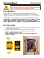
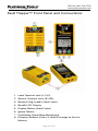
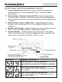
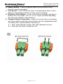
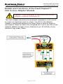
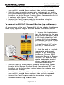
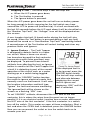
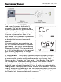
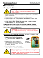
Transient Fault Location for Energized Dedicated Circuit Breakers
TFT100 User Manual
Toll Free: 800-749-5783
www.platinumtools.com
Toll Free: 800-749-5783
www.platinumtools.com
This product should only be used by and connected/
disconnected from a circuit to be tested by qualified
service personnel or certified electricians
Introduction
Fault Trapper™ is a new class of tester intended to locate the
distance to a circuit anomaly that is either intermittently causing a
change in the circuit’s characteristics or blowing the circuit breaker.
Fault Trapper™ can capture and save up to two events (open and/
or short) per test session and save them separately. If the circuit
breaker trips, the backup battery powers the Fault Trapper™ to allow
for an orderly shutdown. The last faults can be viewed using the
battery power. An In-Line Adapter is used to isolate the circuit being
monitored from the breaker panel and all other breakers.
Key Features
• Unattended in-line monitoring of energized dedicated circuits up
to 300 VAC and 40 amps
• Fault Location reported as distance from Fault Trapper™
• Detects a fault whether or not it trips the circuit breaker
• Timer logs elapsed time of tests
• Back-up battery allows capture of breaker trips/Unpowered
display of results
Page 2 of 24
Toll Free: 800-749-5783
www.platinumtools.com
Safety Alert
Symbols
Definition
Warning: Potential for personal injury
Caution: Potential for damage to or destruction of
equipment
Conformité Européenne.
Conforms to European Economic Area directives.
Disposal Information
Warning: Electricity - High Voltage
Warning: Hot Surface
Safety Information
To ensure safe operations of the Fault Trapper™, follow instructions
carefully when using the unit and observe warning and caution
messages listed in this manual. Failure to observe warnings can
result in severe injury or death and can damage the unit.
• Fault Trapper™ is for use only by persons qualified to work in
and around breaker panels.
• Do not use the Fault Trapper™ or cables if they appear damaged
or the unit is not working properly.
• Do not use with voltages and currents higher than what the Fault
Trapper™ is rated for. The Fault Trapper is rated for 110/120VAC
to 230/240VAC branch circuits at a maximum of 40 amps.
• Turn off circuit breaker prior to attaching Fault Trapper™ and
inline adapter to circuit to be monitored.
• Do not use around explosive or flammable gas.
• Use only test leads provided for connecting the Fault Trapper™
to the 40A In-Line Adapter Module.
• Before opening the battery door, remove cables from Fault
Trapper™.
• Always wear personal protective equipment when working with
the Fault Trapper™
• Do not open case of either the Fault Trapper of the In-Line
Adapter (when changing the fuse) with any cables connected to
it.
Page 3 of 24
Toll Free: 800-749-5783
www.platinumtools.com
Contents:
40 Amp In-Line
Adapter
Fault Trapper
Main Unit
Two Plug-in 2-Wire
Terminal Block
Connectors - 8 to 24
AWG (0.2 to 10 mm)
Banana Plug Leader Cable
Page 4 of 24
Toll Free: 800-749-5783
www.platinumtools.com
Insulated 1/8” Screwdriver
(1000V Rated)
Contents (cont.):
• Duracell® 9 Volt Alkaline Battery. (Note - Do not use “Heavy
Duty” Carbon batteries or generic budget batteries.)
• User Instruction Sheet
• Warranty Card
Orderable Accessories and Replacement Parts:
Part Number Description
6075
Spare Plug-in 2-Wire Terminal Blocks (Set of 2)
6076
Replacement Banana Plug Leader Cable
19202
Insulated 1/8” Screwdriver (1000V Rated)
TCA007
Micro-USB Cable
TCA008
Hanging Strap with Carabineer
Page 5 of 24
Toll Free: 800-749-5783
www.platinumtools.com
Fault Trapper™ Front Panel and Connections:
1.
2.
3.
4.
5.
6.
7.
8.
Load Terminal Jack (L1/L2)
Source Terminal Jack (S1/S2)
Banana Plug Leader Cable Jacks
Backlit LCD Display
Display Button (View Faults)
Ignore Button
Test Button (Start/Stop Monitoring)
Distance Buttons (Press & Hold to change to Feet or
Meters)
Page 6 of 24
Toll Free: 800-749-5783
www.platinumtools.com
Front Panel and Connections (Cont.):
1. Load Terminal Jack (L1/L2) - Wire or wires removed from
load attaches here using supplied Plug-in Termninal Block
Connectors
2. Power Source Terminal Jack (S1/S2) - Usually attached to
circuit breaker terminal or terminals, using the supplied plug-in
terminal blocks. Screw on terminal block should be tightened to
7 in/lbs.
3. Banana Plug Leader Cable Jacks - Supplied Banana Plug
Leader Cable connectos 40A In-Line Adaper Module to Fault
Trapper™.
4. Backlit LCD Display - Shows Distance to Fault, Elapsed Time to
Fault, Fault Type (Short/Open), and Battery Status
5. Display Button - Used to power unit on briefly to view faults
when not powered by AC and to toggle between a breaker trip
fault and a non-breaker trip fault, if there is one.
Displayed
Elapsed Time of Test
From the first 0.1 min to 59.9 mins:
The elapsed time will be displayed in minutes
and tenths of a minute (0.1 equals 6 seconds)
From the first hour until 23 hours:
The elapsed time will be displayed as hours
(1h to 23h)
From the first day until the 99th day:
The elapsed time will be displayed as time in
days (1d to 99d)
Page 7 of 24
Toll Free: 800-749-5783
www.platinumtools.com
6. Ignore Button - Press to ignore events that are part of the
circuit’s normal operation.
7. Test Button - Press Button to start a monitoring session. Press
during a monitoring session to stop a test if running.
8. Distance/Units Button - Press and hold the Display and Ignore
buttons for 3 seconds. The “ft” or “m” icons will flash denoting
the new unit used for measurement.
9. Terminal Block Connectors - Insert the circuit wires or jumpers
into these blocks and insert the blocks into the designated jacks.
To remove the Terminal Block Connectors:
a.) push and hold the orange side tabs towards the jack
b.) then pull the block connector out.
Page 8 of 24
Toll Free: 800-749-5783
www.platinumtools.com
Details and Functions of the Fault Trapper™
40A In-Line Adapter Module
Caution - Turn off power to the circuit the In-Line
Adapter is being connected to!
The Fault Trapper measures the wired pair impedance in the circuit
to sense an electrical event as a fault. The 40A In-line Adapter
Module is positioned between the Power Source and the Load on
the breaker. Power for Main Unit is tapped off a coil in the 40A In-line
Adapter Module through a fuse (Littelfuse® p/n 0215.250) via the
Banana Plug Leader Cable.
Page 9 of 24
Toll Free: 800-749-5783
www.platinumtools.com
40A In-Line Adapter Module Connections
VOLTAGE
NEUTRAL/GND BUS BAR SOURCE (CIRCUIT BREAKER)
L1
L2
S1
S2
110/120
VAC
BLACK
WHITE
BLACK
NO
CONNECTION
230/240
VAC
BLACK
RED
BLACK
RED
GFI/AFCI
BLACK
WHITE
BLACK
WHITE
Page 10 of 24
Toll Free: 800-749-5783
www.platinumtools.com
Note! Use only on Energized Dedicated Circuits, Max 40 Amps.
Caution - Turn off power to the circuit the InLine Adapter is being connected to!
Connecting the Fault Trapper 40A In-Line Adapter
Module to Circuit Breakers (USA)
To connect to a 120VAC Standard Breaker (up to 40 Amps)
All connections to the Fault Trapper 40A In-Line Adapter Module are
made using plug-in terminal block connectors; torque screws to 7inlbs:
1. Noting the alignment of the Terminal Block Connector relative
to the Load Terminal Jack on the 40A In-Line Adapter Module,
remove the hot wire from the breaker being tested and insert it
into the Terminal Block Connector so that it is matched with Load
Terminal “L1”. Torque down the fastening screw to 7 in-lbs.
2. Strip the ends off a white jumper wire and connect one end
to the neutral/ground bus bar and insert the other end into
the Load Terminal Block Connector so that it is matched with
Terminal “L2”. Torque down the fastening screw to 7 in-lbs.
Page 11 of 24
Toll Free: 800-749-5783
www.platinumtools.com
3. Insert the Load Terminal Block Connector into the Load Terminal
Jack until it is seated firmly and lock tabs are fully engaged.
4. Strip the ends of another jumper wire and connect one end to
the Circuit Breaker (where the wire was removed in Step 1) and
the other end to the Source Terminal Block Connector so that it
is matched with Source Terminal “S2”.
5. Connect the Fault Trapper meter to the module using the
included Banana Plug Leader Cable.
To connect to 220VAC Standard Breaker (up to 40amps):
All connections to the Fault Trapper 40A In-Line Adapter Module are
made using supplied Plug-in Terminal Blocks Connectors, torque
screws to 7in-lbs:
1. Remove the two hot wires
from the breakers for the load
being tested and attach them
to the Load side of the Fault
Trapper 40A In-Line Adapter
Module with the black in Load
Terminal “L1” and the red wire
in Load Terminal “L2” using
the Plug-in Terminal Block
Connector.
2. Strip the ends of a black
jumper wire and connect
one end of the wire using
the Source Terminal Block
Connector Source at Source
Terminal “S1” and the other
end to the breaker terminal
where the black wire was
removed from in Step 1.
3. Strip the ends of a red jumper wire and connect one end of
the wire to the Source Terminal Block Connector at “S2” and
the other end to the breaker terminal where the red wire was
removed from in Step 1.
4. Insert the Load Terminal Block Connector into the Load Terminal
Jack until it is seated firmly and lock tabs are fully engaged.
5. Connect the Fault Trapper meter to the module using the
included Banana Plug Leader Cable.
Page 12 of 24
Toll Free: 800-749-5783
www.platinumtools.com
To connect to a 120VAC GFI or AFCI breaker (up to
40amps):
All connections to the Fault Trapper 40A In-Line Adapter Module are
made using supplied Plug-in Terminal Blocks Connectors, torque
screws to 7in-lbs:
1. Remove the hot and neutral from the neutral bus bar and attach
them to the load side of the Fault Trapper 40Amp Adapter
Module with the black wire at “L1” and white neutral at “L2”.
2. Keep the curly pigtail neutral white wire from the GFI/AFCI
breaker connected to the Neutral/GND Bus bar.
3. Connect a black jumper wire from the HOT port of the GFI/AFCI
breaker to the Source Terminal “S1”
4. Connect a white jumper wire from the NEUTRAL port of the GFI/
AFCI breaker to the Source Terminal “S2” and connect the Fault
Trapper meter to the module using the included Banana Plug
Leader Cable.
Page 13 of 24
Toll Free: 800-749-5783
www.platinumtools.com
Instructions for Use
After Connecting in one of the configurations above and switching
on the breaker(s).
1. Powering on Unit – Once the unit is powered by the AC power
connection the battery level will be shown
on the display. The unit will be ready at this
point to run a test.
If there is no AC power connection the
Display button can be used to power the
unit on using battery power to show the
results from a previous test.
2. Starting a Test
– While powered by the AC power connection press the Test
button. The Fault Trapper will not run a test under battery power.
The velocity of propagation used for distance measurement is 70%
the speed of light, a nominal value for power wiring, and is not
configurable.
Before you start, note the time.
The Fault Trapper record the elapsed time from when you start
the monitoring to when the fault occurs. You will need to know
the starting time to determine when the fault occurred.
3. Test Running – When a test is started “zero’s” will be scrolling
left to right in the test results area and the up down arrows on the
left side will be flashing until a fault is shown.
Once a fault is found the up down arrows will continue to flash while
the test is running while the distance to the last fault found is shown.
The lower left portion of the screen denotes the time. Before a
fault is found the time will show how long it has been since the test
started. Once a fault is found the last fault will be shown and the time
will show how long the time was between the beginning of the test
and the last fault found.
Page 14 of 24
Toll Free: 800-749-5783
www.platinumtools.com
4. Stopping a Test – The three ways a test can stop are:
a. When the A/C power goes down,
b. The Test button is pressed
c. The Ignore button is pressed.
When the A/C power goes down the unit will run on battery power
for long enough to finish scanning for the fault which may have
caused the A/C to power off (breaker trip). If a fault occurred with
the last 30 seconds before the A/C went down it will be classified as
the “Breaker Trip Fault”, the “Voltage!” icon will be displayed when
this occurs.
A non- breaker trip fault (if found earlier during the test) will also
be saved. When the Test button is pressed during a test any fault
found will be saved as a “Non-Breaker Trip Fault” and testing halted.
A second press of the Test button will restart testing and clear any
previous faults and Ignores.
5. Ignore Feature – The Fault Trapper
is designed to detects faults in a home
run circuit. When a home run circuit
has branches beyond the first contactor
inaccurate results (false positives) may
be displayed. To prevent these branch
artifacts from affecting the test, an Ignore
button is used to tell the Fault Trapper that
a fault it is detecting is part of the normal
operation of the circuit such as a motor
starting up or a switch being toggled.
Pressing the “IGNORE” button teaches
the meter to ignore electrical events that
normally occur on that branch. It will save
the location information and fault type,
“ignore” the fault and resume monitoring.
The ignored fault will be shown on the
screen as a flashing “IGN” icon.
If the displayed fault is
to be ignored, press the
IGNORE button briefly. The test will stop running
and alternate between
displaying the current
fault to ignore and
displaying “IGN” until the
test is restarted.
To set “IGNORE” artifacts, disconnect the HOT wire at the first
contactor, this is where the wires from the panel are no longer
parallel. If it is an electrical outlet, junction box or motor, disconnect
the HOT wire at the first contactor. If the first contactor is a switch,
turn off the switch. This creates an open at these contactors. Start a
test and when the OPEN fault is detected, press the IGNORE button.
Now you can reconnect the outlet or turn the switch back on to
resume your test.
Page 15 of 24
Toll Free: 800-749-5783
www.platinumtools.com
To clear any saved “IGNORE” events
hold down the ignore button for 3
seconds. “Clr” will be shown on the
screen to indicate the ignore fault was
cleared. If the Ignore button is pressed
while testing the test will be stopped.
If ignore is pressed and there is no
fault saved from a previous test dashes
will be shown in the test result area
to denote that no event is currently
ignored.
If the ignored fault occurs during the
last 30 seconds before the A/C power
goes down it will still be shown as the
“Breaker Trip Fault”. The ignored fault
is +/- 3% of the distance to the ignored
fault location (regardless of being a
Short or an Open event).
6. Test Results - The Display button is used to show test results.
If the AC power connection is off the unit will use the 9 volt battery
to power on the display and show the results from the last test.
There can be a “Breaker Trip” fault and a “Non-Breaker Trip” fault.
The voltage icon will flash indicating that the fault shown caused
the breaker to trip. Tap the Display button to cycle between the two
faults (if there are more than one). Ft and M units can be toggled by
holding down the Display and Ignore buttons for 3 seconds. Tap the
Display button to cycle between the two faults (if there are more than
one). Feet (Ft) and Meters (M) units can be toggled by holding down
the Display and Ignore buttons for 3 seconds.
Page 16 of 24
Toll Free: 800-749-5783
www.platinumtools.com
7. Battery Remaining – In the lower right portion of the screen is a
battery icon with bars showing how much remains for the 9V battery.
Three bars shows a full battery, two bars is between 33% and 66%,
one bar is between 33% and 10%. A flashing battery outline icon
shows that there is less than 10% battery life remaining.
Since the test runs for a short time after the A/C power shuts off it is
recommended to replace the 9V battery (with no A/C power present)
once the battery indicator shows one bar or a flashing battery
outline icon.
Page 17 of 24
Toll Free: 800-749-5783
www.platinumtools.com
Maintenance
Changing the Battery
Warning! Remove any cables attached to the
Fault Trapper™ before opening any battery
compartment!
1. Remove screw on rear of unit near the middle with a #1 Philips
head screwdriver.
2. Remove battery and disconnect from battery snaps.
3. Attach a new 9 volt alkaline battery to the battery snaps and
return to battery compartment.
4. Place battery cover in slot and rotate shut. Fasten shut with
screw removed. Do not over tighten!
Replacing the Fuse in the 40A In-Line Adapter Module
The 40A In-Line Adapter Module contains a fuse used to protect
Fault Trapper cabling and circuitry.
Warning! To avoid electrical shock, remove
any cables attached to the 40A In-Line Adapter
Module before opening the case!
Replace fuse with same type and rating! The fuse is a special type
capable of interrupting high current circuits.
1. Remove four case screws using
a T-15 Torx® driver and open the
case.
2. Remove Fuse cover and fuse.
Replacement fuse is Littelfuse®
p/n 0215.250, 5x20 mm, time-lag,
0.25Amp, 250VAC.
3. Replace fuse cover, reassemble
case, replace 4 screws and tighten.
Warning! Never operate 40A In-Line Adapter
Module without the connector side panel being
installed! After servicing the fuse, verify safe state
of case and operation of unit.
Page 18 of 24
Toll Free: 800-749-5783
www.platinumtools.com
Specifications
Physical Dimensions
Fault Trapper Main Unit
Size: 15.25 x 7.6 x 3.8 cm (6.0 x 3.0 x 1.5 inches)
Weight: 255 grams (9 oz.) with battery
40A In-Line Adapter Module
Size: 11.5 x 7.6 x 5.85 cm (4.5 x 3.0 x 2.3 inches)
Weight: 312 grams (11 oz.)
Input Rating:
Fault Trapper Main Unit: 90 to 265 Volts AC RMS 50/60 Hz,
4 Watts max.
40amp In-Line Adapter: 300 Volts AC RMS, 40 amp circuits
maximum, supplies power to main unit
Measurement Method: Spread Spectrum Time Domain Reflectometry
(SSTDR)
Accuracy: Up to 97%
Maximum Length: 300 ft on NM-B or Wire in Conduit
Battery is used to review results when not AC powered
Battery Low Level: Approximately 5.5 volts
Battery Life (9 Volt Alkaline battery, typical)
Standby: 2 years
Active: 4 hours typical
Environmental
Temperature
Operating: 0° to 50°C (32° to 122°F)
Storage temperature: -20° to 60°C (-4° to 140°F)
Long Term Storage w/ battery: 35°C maximum (95°F)
Humidity: 10% to 90%, Non-Condensing
Altitude: 2,000 meters (6,561ft) maximum
Page 19 of 24
Toll Free: 800-749-5783
www.platinumtools.com
Fault Trapper™ FAQ
Does the Fault Trapper Require Batteries?
- Yes, the Fault Trapper requires a 9V battery in the event of Power
Loss from the wires under test. The Fault Trapper requires a
high quality welded cell 9V battery such as Duracell®. Generic
budget batteries may not be sufficient to power the Fault Trapper.
The Fault Trapper main unit does not power up when it is
connected to AC power.
- Check that the Fault Trapper is connected correctly.
- Check the fuse in the 40A Adapter Module. If the fuse is blown, a
replacement can be ordered from Digi-Key® at www.digikey.com,
P/N F4603-ND.
The Fault Trapper does not see a fault when I short the wires to
trip the breaker intentionally.
- If the ignore button has been pressed, the Fault Trapper will
ignore the fault. Press and hold the Ignore button until the LCD
displays “clr”, this clears the ignore feature.
Does the Fault Trapper and 40 Amp Adapter Module work in wet
environments?
- No, the Fault Trapper and 40 Amp Adapter module must be
operated in dry environments.
Can I use my own longer or shorter Banana Jack leader cable
between the Isolation module and main unit?
- No. The impedance, length and voltage rating is critical to safe
and correct operation of the unit.
My unit seems to work fine, but doesn’t save the last event
detected.
- The battery must have enough energy to run the unit for 5
seconds on battery power alone. If your battery is low or poor
quality, the unit may not be powered on long enough to save the
results.
The Fault Trapper doesn’t report the breaker tripping because
of sustained over-current loads; I thought it would tell me where
the fault is.
- The Fault Trapper does not measure current. The Fault Trapper is
designed to locate actual wiring faults. If the over-current event is
Page 20 of 24
Toll Free: 800-749-5783
www.platinumtools.com
from a wiring short (not just the load at the end of the run) it will
be detected as a short at the event distance.
Can I update the Fault Trapper firmware?
- Yes, the Fault Trapper is field updatable using a micro USB
cable and a PC. The 9V battery must be removed to access the
micro-USB connector before updating. Instructions and any
firmware updates are posted at the Fault Trapper page at www.
platinumtools.com.
Will the Fault Trapper detect series and or Parallel arc faults?
- It depends on the nature of the connection/parallel arc
event. When the Fault Trapper detects an open or loose wire
connection for 5 half AC cycles in a row (33mS) it will be
reported as an open fault. Parallel arc detection takes 5 half AC
cycles with low impedance to be detected as a short fault. In
the case of parallel arcing, if the shorting material is blown out,
blown apart, vaporized or someway removed before the 5 half
cycles, it may not be detected as a fault.
How far down a daisy-chained branch circuit would the Fault
Trapper be able to detect faults?
- The Fault Trapper is optimized for monitoring homerun circuits.
Using it to monitor circuits that extend beyond a homerun may
detect a fault but the accuracy of displayed distance to the fault
maybe affected.
Sometimes the circuit breakers are due to ground faults, will the
Fault Trapper detect this?
- The Fault Trapper is capable of detecting electrical events due to
shorts and opens between hot and neutral lines. It will not detect
events due to ground-faults.
Most circuits in a breaker box use dedicated neutrals for each
line, however, there are cases where two hot wires may share
a common neutral. Would this compromise the Fault Trappers
ability to detect a fault?
- The two hot wires have to be different phases, effectively a 240V
line using 120V to the neutral from each phase instead of using
the 240 available across the two hot wires. This should not be a
problem for Fault Trapper; it is effectively the same as a 240 volt
line going to a stove or other appliance.
Page 21 of 24
Toll Free: 800-749-5783
www.platinumtools.com
Notes
Page 22 of 24
Toll Free: 800-749-5783
www.platinumtools.com
Notes
Page 23 of 24
Toll Free: 800-749-5783
www.platinumtools.com
Toll Free: 800-749-5783
www.platinumtools.com
IS TFT100 REV A 11/15


![TECNARE DPA 28X OWNER [Ingles]](http://vs1.manualzilla.com/store/data/005945802_1-b9e6af5d2577bc9a733b6f858960f622-150x150.png)