1
Taylor™ Programmable Controller Interface User’s Guide
Chapter 1 Interface Techniques
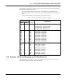
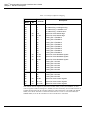
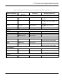
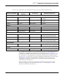
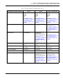
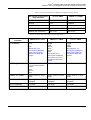
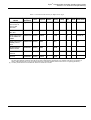
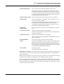
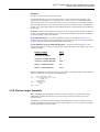
Table 1-2. Example of Effective Mapping
PC Address
Word
Bit
CCF
Channel
Description
700
700
700
700
700
701
702
702
702
702
0
1
2
3
4-15
0-15
0
1
2
3
1
2
3
4
5-6
17-32
33
34
35
36
PC Status Flag - run/program mode
PC Status Flag - booting/running
PC Status Flag - hardware error
PC Status Flag - software error
Spares for future status flags
Spares for future status flags
Cooling Fan 1 Feedback
Cooling Fan 2 Feedback
Cooling Fan 3 Feedback
Cooling Fan 4 Feedback
702
702
702
702
702
703
704
705
705
705
705
705
4
5
6
7
8-15
0-15
0-15
0
1
2
3
4
37
38
39
40
41-48
49-64
49-64
81
82
83
84
85
Cooling Fan 5 Feedback
Cooling Fan 6 Feedback
Cooling Fan 7 Feedback
Cooling Fan 8 Feedback
Spares for future feedback signals
Spares for future feedback signals
Spares for future feedback signals
Cooling Fan 1 Control
Cooling Fan 2 Control
Cooling Fan 3 Control
Cooling Fan 4 Control
Cooling Fan 5 Control
705
705
705
705
706
5
6
7
8-15
0-15
86
87
88
89-96
97-112
Cooling Fan 6 Control
Cooling Fan 7 Control
Cooling Fan 8 Control
Spares for future control signals
Spares for future control signals
707
0-15
113-128
Spares for future control signals
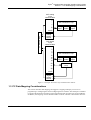
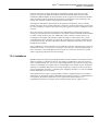
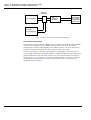
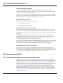
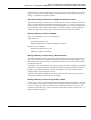
This method does not require any alteration of where status, control, and feedback, or other
coils or registers reside in existing PCs. Instead, two areas of memory are set aside in the PC as
a buffer through which the PC interface and the PC share information. One buffer (the READ
buffer) is for the PC interface to read from and for the PC to write to. The other buffer (the
WRITE buffer) is for the PC interface to write to and the PC to read from.
1-6
3BUR 000 254R0201