1
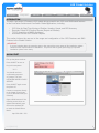
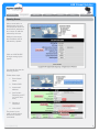
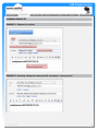
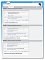
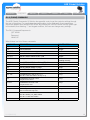
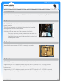
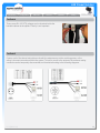
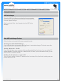
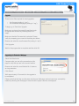
ASE Citadel Solution
Where to Buy:
1-919-850-3100
[email protected]
Introduction
Configuration
SIM Card
Antenna
Installation
Testing
Troubleshooting
Contacts
For additional information about this Product warranty, please contact your Service Provider or Pointof-Sale. For additional information about ASE products and services, please contact ASE as follows:
Mail:
Telephone:
Facsimile:
Website:
E-mail:
Applied Satellite Engineering, Inc.
16559 North 92nd Street, Suite 101
Scottsdale, Arizona 85260 USA
480.443.1424
480.452.0971
www.ase-corp.com
[email protected]
Mail:
Telephone:
International Branch
Applied Satellite Engineering, Intl.
93 An Creagan
Barna, County Galway
Republic of Ireland
353 85 761 5506
Table of Contents
Introduction..........................................................................................................................................................................................2
Introduction...................................................................................................................................................2
Overview .......................................................................................................................................................................................3
Life Cycle ....................................................................................................................................................................................3
Configuration ............................................................................................................................................................................5
Introduction...................................................................................................................................................5
Quick-Start
....................................................................................................................................................5
Remote Configuration and Query...............................................................................................................................................9
ASE Commands.........................................................................................................................................................................9
Command Examples................................................................................................................................................................11
Phone Commands....................................................................................................................................................................13
Warnings and Limitations.........................................................................................................................................................14
SIMCard.................................................................................................................................................................................................15
Introduction...................................................................................................................................................15
Standard SIM Card...................................................................................................................................................................15
Captain’s SIM Card...................................................................................................................................................................17
Antenna .........................................................................................................................................................................................19
Introduction..........................................................................................................................................................................19
Installation Tips/Troubleshooting..............................................................................................................................................20
Installation.........................................................................................................................................................................................23
Introduction..........................................................................................................................................................................23
Connecting Power, Phone, and Internet....................................................................................................................................24
Testing .........................................................................................................................................................................................25
Introduction...........................................................................................................................................................................25
Installation Check Sheet...........................................................................................................................................................26
Tests.............................................................................................................................................................................27
Maintenance.............................................................................................................................................................................28
Troubleshooting..................................................................................................................................................................................29
Cable Diagram..........................................................................................................................................................................29
Phone Buttons and Features....................................................................................................................................................30
Error Tones ..............................................................................................................................................................................30
Wiring Test Points................ ..................................................................................................................................................32
Firmware Upgrade....................................................................................................................................................................34
Internet Connection..................................................................................................................................................................36
V1.2 [2012-7-6]
1
ASE Citadel Solution
Where to Buy:
1-919-850-3100
[email protected]
Introduction
Introduction
Configuration
SIM Card
Antenna
Installation
Testing
Troubleshooting
Introduction
The ASE Citadel (Safe-Room) Solution is a powerful telephony and positioning reporting solution that
operates over the Iridium network, which enables it to provide truly global coverage.
Within the safe room, the ASE Citadel Solution features voice communications and GPS-position
reporting. This solution may also be remotely polled securely from the ship’s offices or company
headquarters. Furthermore, configuration may be performed remotely as well.
The safe-room solution solves antenna run problems by combining the transceiver and the antenna
into one small, discreet enclosure that may be concealed when mounted since antenna distance is not
an issue. A corded phone, mounted in a lockable wall-mounted cabinet, may be easily installed in the
Citadel with only one cable running to the outdoor unit. An additional phone can be installed on the
bridge from the same system to ensure a complete emergency communications system.
NOTE
The Citadel Solution may be referred to as the “Citadel”, the “Antenna”, or the “ComCenter”
interchangeably as the antenna, transceiver, and receiver are all contained within the same
enclosure. You may also refer to the ComCenter Outdoor User’s manual for more detailed
information.
QUESTIONS
If at any time, you have questions or concerns about either the installation or operation of your
Citadel, please visit www.ase-corp.com or contact us using the information located on the cover
of this manual.
V1.2 [2012-7-6]
2
ASE Citadel Solution
Where to Buy:
1-919-850-3100
[email protected]
Introduction
Introduction
Configuration
SIM Card
Antenna
Installation
Testing
Troubleshooting
PRECAUTIONS
Please read and understand this User’s Manual before installing your Citadel Solution. Careless
or incorrect installation can degrade performance, damage both new and existing equipment, and
incur unexpected network airtime charges.
OVERVIEW
The following table contains the steps required to configure, install, test, and maintain the ASE Citadel
Solution. Additionally, descriptions of the persons who might be involved in placing the solution in
service as well as solution maintenance may be included.
STEPS
PERSONS RESPONSIBLE
NOTES
Configuration
Ship’s IT personnel
Configures email alerts, reporting, etc.,
prior to deployment
SIM activation
Ship’s IT personnel
Ensures that activation occurs with the
Iridium network
Antenna installation
survey
Ship’s owners/engineers
Optimizes satellite coverage while
addressing thermal concerns
Solution installation
survey
Ship’s owners/engineers
Identifies cable run length(s) and the
location of the junction boxes and phone
cabinet
Physical installation
Ship’s engineers and other
installers
Instructions for mounting and
installation
Testing after installation
Crew/ship’s engineers
Verifies whether solution is
operating correctly
In-service testing
Crew and/or IT personnel
Ensures solution is operating properly
while in service
Maintenance
Crew/ship’s engineers
Proper maintenance ensures
functionality and extends life
LIFE CYCLE
Cabling Distance Assessment
Conducting a site survey reveals the cable length(s) required for installation.
Antenna Site Survey
The antenna site survey evaluates where the antenna should optimally be located. This involves
considering the following tradeoffs:
The antenna is often “hidden”, which might bring inherent blockages.
Tradeoffs between the visibility to the satellites and the line-of-sight to the satellites.
Verify Usage of Current Firmware
Ensure that Citadel Solution is using the most current firmware version.
V1.2 [2012-7-6]
3
ASE Citadel Solution
Where to Buy:
1-919-850-3100
[email protected]
Introduction
Introduction
Configuration
SIM Card
Antenna
Installation
Testing
Troubleshooting
Life Cycle (Continued)
Upgrade If Needed
If the firmware version of Citadel Solution currently being used is not the most current one, upgrade it.
Configure Settings
The Citadel requires configuration prior to its deployment. This is done via the embedded webpage,
as explained in CONFIGURATION.
Activate SIM Card
Activate the phone’s SIM card. Follow the directions included in SIM CARD ACTIVATION.
Test Outgoing Call/Outgoing GPS
After installation, the solution requires testing. This includes an outgoing voice call. It may also
include a test-GPS report sent via the Handset. ASE recommends testing at least one in-bound call
as well as trying the remote polling feature if the user plans to rely on this aspect of its design.
Install Antenna (ComCenter)
The antenna is installed using the V-Bolts.
Route Cable
The antenna’s associated cabling is routed throughout the ship.
Mount/Install Phone Cabinet
The phone cabinet must be mounted and connected appropriately. An optional Uninterrupted Power
Supply (UPS) or battery backup may be installed for emergencies.
Test Voice Out/Voice in GPS Reporting
Weekly Voice Call Test
To ensure continuing viability of the Citadel Solution, it should be tested weekly.
Test Daily in HRA
In addition to testing daily while in High-Risk Areas (HRAs), it is recommended that testing be
performed just prior to entering these zones.
Maintenance
Limited maintenance is required to keep the Citadel operating at peak performance.
Where to Buy:
Mackay Communications, Inc.
3691 Trust Drive
Raleigh, NC 27616 USA
Tel: 1-919-850-3100
US Toll: 1-877-4-MACKAY
Fax: 919-954-1707
Email: [email protected]
www.mackaysatellite.com
V1.2 [2012-7-6]
For Government buyers or contractors,
contact Mackay Government at:
[email protected]
or 904-880-4633
4
ASE Citadel Solution
Introduction
Configuration
Configuration
SIM Card
Antenna
Installation
Testing
Troubleshooting
INTRODUCTION
The ASE ComCenter II Firmware v2.25 update brings powerful new GPS- and SMS-based features
to the ComCenter Outdoor and ComCenter Citadel applications, including:
•
•
•
•
GPS View for Real-Time Viewing of Position, Heading, Speed, and GPS Accuracy
Remotely Polled GPS Position Reports (Report on Demand)
TCP/IP acquisition of NMEA Sentences
Automatic Periodic GPS Position Reports
This section informs the user as to the usage and configuration of the GPS Features and SMS
Features in the Citadel Solution.
IMPORTANT
If you are in doubt about the mounting steps or the connectivity at any stage of this installation, please
contact an ASE representative for assistance. They will be able to guide you through your specific
installation options more clearly.
QUICK-START
Pick up the phone receiver.
Press ON/OFF to turn on.
Key in this sequence:
*612
You should receive a
confirmation sequence
of 2 beeps. This sets
NETWORK MODE to DHCP
SERVER.
Press ON/OFF again to turn
the phone off.
Connect a computer directly
to the Citadel (ComCenter
II) via an Ethernet cable (not
included).
Open a Web browser. If the
following screen does not
appear automatically, type
this into the address bar
to reach the Citadel Direct
Mode:
http://198.168.1.100
V1.2 [2012-7-6]
5
ASE Citadel Solution
Introduction
Configuration
Configuration
SIM Card
Antenna
Installation
Testing
Troubleshooting
Opening Screen
When connected to a
Web browser, the local
is displayed as shown at
the default IP address or
at a custom IP address
selected by the user.
Within this document,
this IP address will be
indicated by <ipadd>.
Click on CONFIGURE
to begin setting up the
system.
You should then see the
following screen:
Follow these steps:
1. Enter Vessel
Name
2. Enable SMS
3. Insert email
address
4. Set Periodic
Reporting to OFF
(or some other
time)
5. Choose a
Password
6. Click SAVE
The phone is now
ready to send reports
and receive remote
commands.
V1.2 [2012-7-6]
6
ASE Citadel Solution
Introduction
Configuration
Configuration
SIM Card
Antenna
Installation
Testing
Troubleshooting
GPS View for Real-Time Viewing of Position, Heading, Speed, and GPS Accuracy
When connected to a
Web browser, the GPS
information is displayed
as shown at the GPS
page of the user-created
IP address, or <ipadd>/
gps.htm:
PARAMETERS
DESCRIPTION
Latitude
Degrees and Decimal Minutes
Latitude
Degrees and Decimal Minutes
Heading
True Track in Degrees
Speed
Nautical Miles
HDOP
Horizontal Dilution of Precision provides information about the
accuracy of the position report
>3.0 Error > +/- 10 meters, Invalid Position report
<2.0 Error +/- 5 meters
<1.0 Error +/- 2 meters
Num Sat
Number of Satellites in view
UTC Date, Time
Date, Time of Displayed Fix
V1.2 [2012-7-6]
7
ASE Citadel Solution
Introduction
Configuration
SIM Card
Antenna
Installation
Testing
Troubleshooting
TCP/IP acquisition of NMEA Sentences
In addition to having the MEA Sentences viewable in the GPS View, they are also accessible at any
time using AT commands over the TCP/IP socket.
Connect to socket at <ip addr>:23 and execute the following AT commands:
AT+INMEA_GPGGA?
AT+iNMEA_GPVTG?
AT+iNMEA_GPRMC?
returns the GPGGA sentence
returns the GPVTG sentence
returns the GPRMC sentence
Emergency Reporting (*911)
An emergency alert can be transmitted by pressing *911 on the connected Analogue/RJ11 Phone.
A triple-beep tone on the Analogue/RJ11 phone provides an indication that the message was
transmitted. The following instructions must be followed for an emergency report to be transmitted
successfully:
•
•
•
•
•
The emergency alert will be sent as an SMS email to the email address entered into the
“Send Message To” field.
The “from” field in the received email will include the phone number of the device.
The “body” in the received email will have the message:
ºº “Emergency Alert sent from <vessel_name> at location <gps position>”
Vessel Name and Send Message To email address must be configured by the user.
The alert will NOT be sent if:
ºº an email address has not be configured.
ºº the ComCenter link to the satellites is not available.
Automatic Periodic Reporting
An automatic periodic report can be transmitted at pre-configured intervals.
The following instructions must be followed for an automatic periodic report to be transmitted
successfully:
•
•
•
•
•
•
The report must be sent as an SMS email to the email address entered into the “Send Message
To” field.
The “from” field in the received email will include the phone number of the device.
The “body” in the received email will have the message as entered by the user.
The keyword “$GPS_POS” in the message will be replaced with the current location.
The keyword “$VESSEL” in the message will be replaced with the vessel name.
Vessel Name and Send Message To email address must be configured by the user.
V1.2 [2012-7-6]
8
ASE Citadel Solution
Introduction
Configuration
Configuration
SIM Card
Antenna
Installation
Testing
Troubleshooting
Report On-Demand
A position report can be sent on demand from a remote site. The request must be an (SMS)
email message with a valid password and valid message format. The replied report will be to the
requester email address.
For details on request format and methodology, see Remote Configuration and Query below.
REMOTE CONFIGURATION AND QUERY
Some configuration parameters can be set from a remote site. The request must be an SMS email
message with a valid password and valid message format. The replied query or configuration
update status will be to the requester email address.
To execute the remote configuration successfully, the email fields must be formatted in accordance
with the following parameters:
From: Returned email
To: The Iridium Phone [email protected]
Subject: Can be anything
Body: ASE Commands only
Other points that must be considered include:
• ase#password#field:data#field2:data# ..... #
• password must match and must be >= 4 characters
• For parameters also configurable via Web page, Web should be updated with new information
upon browser REFRESH
• password is CASE SENSITIVE
• all others are NOT case sensitive
• “:?” sends the value of the field as a report
• responses and reports are only sent if a valid email address has been set up previously
ASE COMMANDS
Remotely Enable/Disable Automatic Reporting
ASE#<password>#PSMS:<value># ON | OFF
Remotely Setting New Email For Reports
ase#password#PSMSTO<email>:?#
Remotely Request Current Position
ASE#<password>#POSITION:?#
Returns the current location information. See Example 1.
V1.2 [2012-7-6]
9
ASE Citadel Solution
Introduction
Configuration
Configuration
SIM Card
Antenna
Installation
Testing
Troubleshooting
Remotely Set Automatic Reporting Rate: OFF To 1 Week Interval
ASE#<password>#PSMSRATE:<value># 0:8
VALUE for Periodic Reporting
RATE of Periodic Report
0
OFF
1
30 minutes
2
1 hour
3
4 hours
4
8 hours
5
12 hours
6
24 hours
7
48 hours
8
1 week
Sets the Automatic Reporting Rate. See Example 2.
Remotely Set Reporting Email Destination
ASE#<password>#PSMSTO:<value># emailaddr
Sets the Automatic Reporting Destination. See Example 3.
Remotely Setting Vessel Name
ase#password#VESSEL:name#
See Example 4.
Remotely Changing Password
ase#password#PASSWORD:newpassword#
See Example 5.
V1.2 [2012-7-6]
10
ASE Citadel Solution
Introduction
Configuration
SIM Card
Antenna
Installation
Testing
Troubleshooting
COMMAND EXAMPLES
EXAMPLE 1: Request for position
EXAMPLE 2: Remotely setting the remote periodic reporting to “once per hour”
V1.2 [2012-7-6]
11
ASE Citadel Solution
Introduction
Configuration
SIM Card
Antenna
Installation
Testing
Troubleshooting
EXAMPLE 3: Remotely changing the email address
EXAMPLE 4: Remotely setting the vessel name
EXAMPLE 5: Remotely setting a new password
V1.2 [2012-7-6]
12
ASE Citadel Solution
Introduction
Configuration
SIM Card
Antenna
Installation
Testing
Troubleshooting
RJ-11 (PHONE) COMMANDS
The ASE Citadel (Comcenter II) Solution has powerful control over the system’s settings through
the use of the phone. For parameters also configurable via the Web page, these parameters
should be updated upon browser REFRESH. By pressing the ON/OFF button until the green light
is illuminated, then entering “*” and keypad numbers, the user can change many settings.
The RJ11 Command Sequence is:
OFF HOOK
‘*’
command
HANG UP
What follows is a list of these commands:
COMMAND
DESCRIPTION
CONFIRMATION
12345
restores defaults
3 beeps
1111
unlocks SIM PIN
3 beeps
201 - 205
sets volume level
NONE
500 | 501
sets USA911 feature to OFF | ON
3 beeps
510 | 511
sets NET ALERT feature to OFF | ON
3 beeps
520 - 523
Not Applicable
Verifies whether solution is
operating correctly
530 | 531
sets CAPTAIN CARD SmartDial to OFF | ON
3 beeps
540 | 541
sets PBX SIGNALING feature to OFF | ON
3 beeps
610
sets NETWORK MODE to FIXED
1 beep
611
612
640 - 648
sets NETWORK MODE to DHCP Client
sets NETWORK MODE to DHCP Server
sets PSMS RATE to OFF or rate 1 to 7
must have valid email address already set up
sets REMOTE ACCESS to OFF
sets password to NULL
sets REMOTE ACCESS to ON
sets password to xxxx
reboots system
dials from phone book entry xxx
does not work with Capt Card
sends EMERGENCY MESSAGE
must have SEND_VIA_SMS enabled
must have a valid email address
query network mode
2 beeps
3 beeps
3 beeps
650
651xxxx
666
7xxx
911
994
V1.2 [2012-7-6]
3 beeps
3 beeps
NONE
dialing tones
3 beeps
1 to 3 beeps
13
ASE Citadel Solution
Introduction
Configuration
SIM Card
Antenna
Installation
Testing
Troubleshooting
Warnings and Limitations
Both GPS and SMS technologies have tremendous capabilities, but are not without limitations.
Included below are indications that advise the user of these technology limitations.
• The accuracy and update rate of the GPS webpage is not guaranteed. Do not use this
product for navigational guidance purposes.
• SMS messaging is NOT a guaranteed delivery service. Successful SMS transmission
results in 3 beeps for confirmation. Failure to transmit yields no notification beeps.
V1.2 [2012-7-6]
14
ASE Citadel Solution
Introduction
Configuration
SIM Card
Card
SIM
Antenna
Installation
Testing
Troubleshooting
INTRODUCTION
Service Providers (SP) offer a choice of two varieties of SIM cards for the Iridium network:
1. A STANDARD SIM card
2. A CAPTAIN’S SIM card
Accessing the Iridium network requires working with the service provider to obtain and register the
SIM card. It is a good idea to keep a copy of the registration email since it may contain PIN numbers
and other important information.
STANDARD SIM CARD
Activating a Standard SIM Card
Determine Whether the Phone is Working Correctly
Mount the Citadel with excellent visibility of the sky.
Open the phone cabinet to access the white Citadel phone.
Press the ON/OFF button so that the green light appears.
Listen for a tone. What is heard should be the following sequence repeating:
HI-LO HI-LO HI-LO beep beep beep
Hearing this indicates that:
•
•
the phone is working correctly.
the SIM card needs to be unlocked.
Unlocking the SIM Card
Dial the following sequence:
* 1111
Press the ON/OFF button to extinguish the green light.
The phone is now unlocked.
Dialing with a Standard SIM Card
Making an Outward Call
Press the ON/OFF button so that the green light appears.
Listen until a constant tone begins.
To dial out, press this sequence:
00 (Country Code) (Area Code) (No.) #
V1.2 [2012-7-6]
15
ASE Citadel Solution
Introduction
Configuration
SIM Card
Card
SIM
Antenna
Installation
Testing
Troubleshooting
Dialing with a Standard SIM Card (continued)
EXAMPLE 1: Dialing a number in the U.S.
00 1 XXX XXX XXXX #
EXAMPLE 2: Dialing a number in the U.K.
00 44 XX XXX XXX #
Iridium provides a free test number for dialing without charges, tariffs, or duties.
EXAMPLE 3: Dialing the Iridium Free Test Number
00 1 480 752 5105 #
V1.2 [2012-7-6]
16
ASE Citadel Solution
Introduction
Configuration
SIM Card
Card
SIM
Antenna
Installation
Testing
Troubleshooting
CAPTAIN’S SIM CARD
Activating a Captain’s SIM Card
Determine Whether the Phone is Working Correctly
Mount the Citadel with excellent visibility of the sky.
Open the phone cabinet to access the white Citadel phone.
Press the ON/OFF button so that the green light appears.
Listen for a tone. What is heard should be the following sequence repeating:
HI-LO HI-LO HI-LO beep beep beep
Hearing this indicates that:
•
•
the phone is working correctly.
the SIM card needs to be unlocked.
Unlocking the SIM Card
Dial the following sequence:
* 1111
Press the ON/OFF button to extinguish the green light.
The phone is now unlocked.
Disabling the Captain’s PIN
Open the phone cabinet to access the white Citadel phone.
Press the ON/OFF button so that the green light appears.
Dial the following sequence:
698 698 #
What is heard will be an automated operator requesting that the CAPTAIN’S PIN be entered. This is
found in the registration email. A typical PIN is 4 numeric characters.
Press Option 4 to disable the PIN.
A message indicating that the SIM card is now unlocked should appear.
The PIN code is no longer required.
Press the ON/OFF button to extinguish the green light.
V1.2 [2012-7-6]
17
ASE Citadel Solution
Introduction
Configuration
SIM Card
Card
SIM
Antenna
Installation
Testing
Troubleshooting
Dialing with a Captain’s SIM Card
Making an Outward Call
Press the ON/OFF button so that the green light appears.
To dial out, press this sequence:
698 (Country Code) (Area Code) (No.) #
EXAMPLE 1: Dialing a number in the U.S.
698 1 XXX XXX XXXX #
EXAMPLE 2: Dialing a number in the U.K.
698 44 XX XXX XXX #
Iridium provides a free test number for dialing without charges, tariffs, or duties.
EXAMPLE 3: Dialing the Iridium Free Test Number
698 1 480 752 5105 #
V1.2 [2012-7-6]
18
ASE Citadel Solution
Introduction
Configuration
SIM Card
Antenna
Antenna
Installation
Testing
Troubleshooting
INTRODUCTION
The ASE Citadel Solution is a powerful communications device that serves as a vital safety tool for
ships on the high seas.
One of the most crucial aspects of installation is determining where to place the antenna on the ship.
In this sense, locating the antenna does not refer to finding the antenna so much as it means placing
the antenna. Since not all ships are designed the same way, ASE has developed several Citadel
installation options along with some installation accessories that are available for purchase.
ComCenter Mounting
The ComCenter II Outdoor with GPS can be mounted easily and is small enough to keep hidden from
view. The unit has a configuration where the antenna and transceiver are contained together. This
design eliminates typical antenna cabling distance limitations. The ComCenter II Includes a VibrationDampening Universal Mount.
The Vibration-Dampening Universal Mount fits flat-face beams as well as vertical and horizontal
railings between 1 in. and 2 in. in diameter.
An alternative mounting option is the Vibration-Dampening Pole Mount. See Optional Accessories for
more details.
Cabling
Routing a single cable from the hidden ComCenter II unit to the Citadel Safe Room achieves secure
voice and data communications for the system.
ComCenter II Cable has a length of 47 m (150 ft) and combines RJ-11, RJ-45, and power in a single
cable. It includes a breakout cable as well as a power adapter.
The extended version has a 100 m cable with a junction box.
Cabinet
The system’s latching wall cabinet is easy to install on any ship. This cabinet houses a corded phone
and features the option for hooking up additional phones.
The Wall Mount RJ-11/POTS Phone in Latching Cabinet features a placard inside that has dialing/
emergency instructions. This cabinet includes an RJ-11/POTS phone, as well as 15 m (50 ft) of 2-wire
RJ-11 cable and a splitter for additional phones.
The extended version has a 100 m cable with a junction box.
V1.2 [2012-7-6]
19
ASE Citadel Solution
Introduction
Configuration
SIM Card
Antenna
Antenna
Installation
Testing
Troubleshooting
Optional Accessories
•
If needed, ASE recommends adding a battery backup to the system. Our recommended
Uninterrupted Power Supply (UPS) automatically turns on when power is lost or intentionally
shut down. A well-maintained battery backup has the capability of powering the system for
100 hours in standby mode, or 55 hours of talk time. Designed specifically for maritime use,
this backup is housed within a steel wall-mounted case with replaceable 10 year batteries.
•
For installations requiring more cable than what is included with the required system products,
Cable Extensions are available.
•
The Vibration-Dampening Pole Mount Bracket fits standard 1 in. NPT pipe threads.
INSTALLATION TIPS/TROUBLESHOOTING
Mounting
The Citadel can be mounted on a “rail” as shown below. An alternative mounting configuration rotates
the V-bolts by 90 deg so that the Citadel can be mounted on a vertical structure, such as a pipe.
V1.2 [2012-7-6]
20
ASE Citadel Solution
Introduction
Configuration
SIM Card
Antenna
Antenna
Installation
Testing
Troubleshooting
Antenna Placement
Antenna placement is very important for maintaining
proper Iridium Satellite Service operation. The ideal
installation should have a 360 deg view of the sky with
no obstructions 8 deg off the horizon.
Many ship’s engineers make the decision to hide
the antenna. The choice of location with regard to
blockage and satellite visibility trade-offs are the
ultimate decision of each ship’s owner.
Satellite Visibility
If this visibility must be compromised,
satellite accessibility will be reduced
some percentage of the time.
V1.2 [2012-7-6]
21
ASE Citadel Solution
Introduction
Configuration
SIM Card
Antenna
Antenna
Installation
Testing
Troubleshooting
Temperature Restrictions
The antenna is often installed hidden from view near
the ship’s funnel. Since the exposed antenna is rated
for a temperature range of -40°C to 70°C, it must be
placed away from heat vents or other heat sources.
If not, permanent damage may occur from exposing
the antenna to temperatures above the operating
specification.
V1.2 [2012-7-6]
22
ASE Citadel Solution
Introduction
Configuration
SIM Card
Antenna
Installation
Installation
Testing
Troubleshooting
INTRODUCTION
Prior to beginning the installation of the Citadel, take a quick inventory to ensure that you have all the
necessary components.
Standard components of the Citadel include:
•
•
•
•
•
•
Citadel antenna
Cable
Junction panel or junction box
Power adaptor
Latchable phone cabinet with handset
15 m (50 feet) of RJ11 telephone cable
Optional component(s):
•
Uninterrupted Power Supply (UPS) battery backup
Once you have identified your preferred location of antenna installation, adjust the V-Bolts to
accommodate either a vertical or horizontal placement. A horizontal orientation is shown in the image
above.
Antenna Mounting
Mount the antenna with the “seam” parallel with the horizon and keep blockage to a minimum. For
more information about placement, see “Locating the Antenna” to review placement if needed.
Cable Routing and Attachment to the Antenna
Choose the best pathway and route the cable from the antenna to the Citadel location. If extensions
are used, connect these as needed.
Connect the end opposite the antenna to the junction panel (or junction box).
Phone Cabinet Installation
Install the phone cabinet wherever it is desired. It is easiest to use the four mounting “bosses” on the
back of the phone cabinet. Install using best judgment based upon the installed location.
V1.2 [2012-7-6]
23
ASE Citadel Solution
Introduction
Configuration
SIM Card
Antenna
Installation
Installation
Testing
Troubleshooting
CONNECTING POWER, RJ11 (PHONE) AND RJ45 (ETHERNET)
Case 1:
When the Optional Harland Simon Battery Backup (UPS) Is Not Installed/Used
Connect the AC power cord to the ship’s power (100-240 VAC). Then connect the AC-DC Power
adaptor to the junction panel (or junction box) using the plug. Be certain to tighten the screw portion
of the jack to secure.
Connect the RJ11 from the phone cabinet to the junction panel or junction box.
If using a laptop (or other computer), connect a CAT-5 ethernet cable (not included) from the laptop to
the junction panel (or junction box).
Case 2:
When the Harland Simon Battery Backup (UPS) Is Being Used
To prepare the UPS, please follow the instructions that came with the unit. Additionally, ASE
recommends following these steps as well:
•
Install the conductor strap between the NEG (-) Terminal on the left battery to the POS (+)
terminal of the left battery. The two batteries will then be in series to provide +24 VDC.
•
Connect main power to the correct terminals inside the UPS.
•
You may use the jack and cord from the power adaptor to the +24 V terminals to connect to
the junction panel or junction box.
•
Consult the UPS manual for testing and troubleshooting guidelines.
V1.2 [2012-7-6]
24
ASE Citadel Solution
Introduction
Configuration
SIM Card
Antenna
Installation
Testing
Troubleshooting
INTRODUCTION
ASE recommends frequent testing of the Citadel Solution. At a minimum, this means testing the
Citadel on a weekly basis. This testing should be made a part of the Ship’s Security Assessment and
Ship’s Security Plan (SSA and SSP).
The first testing procedure should begin shortly after the Citadel is installed on the ship. Consult the
Installation Check Sheet for details on the procedure.
V1.2 [2012-7-6]
25
ASE Citadel Solution
Introduction
Configuration
SIM Card
Antenna
Installation
Testing
Testing
Troubleshooting
INSTALLATION CHECK SHEET
Ship Name or ID:
IMEI:
Date:
Tested by:
Test
Pass
Check for dial tone 10 minutes after
system power up
Place outgoing call
Place outgoing call 2 minutes later
Place outgoing call 4 minutes later
Place outgoing call 6 minutes later
Place outgoing call 8 minutes later
Place incoming call
Fail
V1.2 [2012-7-6]
Notes
26
ASE Citadel Solution
Introduction
Configuration
SIM Card
Antenna
Installation
Testing
Testing
Troubleshooting
TESTS
System Test
Once installation is complete, the system can be powered up and tested. What follows is the
recommended initial testing procedure:
Install a SIM card in the antenna (if one has not already been installed).
Apply power to the system.
Wait 5 -10 minutes to allow for the system to initialize. This enables the Citadel to locate the satellites
and then register on the Iridium network.
Retrieve the RJ-11/POTS phone from inside the lockable cabinet.
Press the ON/OFF key so that the light turns green and the dial tone may be heard.
Consult the following dialing procedures to place an outgoing test call:
•
•
For a Standard SIM card: 00(country code)(area code)(number)#
For a Captain’s SIM: 698(country code)(area code)(number)#
Place an outgoing test call.
Placing an incoming test call involves arranging for land-based personnel to call the ship. When
receiving an incoming call, the RJ-11/POTS phone rings. Answer by pressing the ON/OFF button until
it turns green.
If this procedure cannot be completed, please refer to the Troubleshooting section.
Voice Tests
Voice Testing encompasses the following types:
•
•
Outbound Voice Call
Inbound Voice Call
Testing an Outbound Voice Call can be accomplished by dialing the ship’s offices, etc. Another
method is by choosing to make a tariff-free Iridium call by dialing:
00 1 480 752 5105 #
698 1 480 752 5105 # (when using a Standard SIM Card)
(when using a Captain’s SIM Card)
For an inbound call, it is recommended that you coordinate with land-based personnel.
V1.2 [2012-7-6]
27
ASE Citadel Solution
Introduction
Configuration
SIM Card
Antenna
Installation
Testing
Testing
Troubleshooting
Safety Preparation
Increase the frequency of testing to once per day when preparing to enter the High Risk Areas
(HRAs).
Since this requires voice dialing, please revisit pp. 15-18 in the SIM Card section for voice dialing
procedures.
In the event that a ship comes under attack, NATO forces request that the crew of the distressed ship
dial a central number to coordinate a response. Because of this, it is strongly recommended that the
phone number for NATO forces be prominently displayed near the phone.
The UKMTO office in Dubai serves as the primary point of contact between merchant shipping and
the naval forces patrolling the waters off the Somali coast. Iridium’s calling plan allows users to use
UKMTO +971 to connect to the Iridium network free of charge.
Please review these procedures with your ship’s security officer to ensure the number is correct.
GPS Positioning
ASE recommends the testing of GPS positioning frequently. This is done by pressing the following
sequence:
*911
Remote Polling
It is recommended that the remote polling features be tested to ensure that the Citadel Solution is
operating properly.
Please see the Configuration section to review remote polling features and procedures.
MAINTENANCE
Clean the antenna portion periodically. Conduct a physical inspection to verify that the antenna
remains horizontal and that the mounts remain tight.
V1.2 [2012-7-6]
28
ASE Citadel Solution
Introduction
Configuration
SIM Card
Antenna
Installation
Testing
Troubleshooting
CABLE DIAGRAM
The diagram below shows typical wiring between the antenna and a Citadel safe room. Voltages may
be checked at indicated locations to confirm wiring or troubleshoot.
V1.2 [2012-7-6]
29
ASE Citadel Solution
Introduction
Configuration
SIM Card
Antenna
Installation
Testing
Troubleshooting
Troubleshooting
RJ-11/POTS PHONE BUTTONS AND FEATURES
ON/OFF Key
This is used to initiate a call or to answer an incoming call.
Initiate a call by pressing this button. The button will turn green
and a dial tone will be heard. Enter the dialing sequence on the
numbered keypad and press the # key to place the call. The
Iridium ‘bleeps’ will be heard followed by ringing of the party being
called.
Answer an incoming call by pressing the ON/OFF key until it turns
green.
Ringer Volume Switch
Set this switch to turn off the incoming ringer or to set to the
desired incoming ring volume. Settings are: OFF – LOW – HI.
Volume Control
This button toggles the volume level of the phones speaker in three steps: LOW – MED – HI.
Pressing this button repeatedly cycles through these settings.
Star / Asterisk Key (*)
ComCenter II setup commands are initiated with this key. See the User’s Manual for a complete list of
setup commands.
Pound / Hash Key (#)
This key must be pressed to initiate an entered dialing sequence.
RJ-11/POTS ERROR TONES
When the ON/OFF key is pressed and turns green, one or more of the following tones may be heard:
Dial Tone
Continuous tone that indicates the system is ready and a call can be placed.
IMPORTANT: If the phone is left on (green light) for an extended period, the Dial Tone will change to
a rapid stutter tone to alert the user that the phone is active but not in use. The phone needs to be
turned off to receive incoming calls.
Stutter Tone
This is an alert tone indicating that the phone is active but not in use, and should be turned off to
allow the system to receive calls.
Error Tones
The table on the next page shows additional error tones to help identify the status or indicate
problems with the system.
V1.2 [2012-7-6]
30
ASE Citadel Solution
Introduction
Configuration
SIM Card
Antenna
Installation
Testing
Troubleshooting
Troubleshooting
Status and Error Tones
Description
Tone Name
Tone Pattern
Powering UP Initialization
NOT READY TONE
<long time><bleep>...repeat
Searching for Network
NOT READY TONE
<long time><bleep>...repeat
Ready to Dial
DIAL TONE
<continuous dial tone>
Enter ASE Access PIN CODE
PIN CODE BEFORE DIAL
<pause><bleep>...repeat
Device on Data Call
BUSY TONE
<continuous busy tone>
Poor Signal during Call
POOR SIGNAL
<bleep><bleep>
Missing SIM Card
ALERT TONE + BEEP COUNT
Alert Tone + 2 beeps
Locked SIM Card
ALERT TONE + BEEP COUNT
Alert Tone + 3 beeps
Registration Denied
ALERT TONE + BEEP COUNT
Alert Tone + 4 beeps
Bad SIM Card
ALERT TONE + BEEP COUNT
Alert Tone + 5 beeps
We understand that describing tones is difficult with words. Therefore, we have made available
“wave” files that play the actual tones. Please contact us to gain access to these files.
V1.2 [2012-7-6]
31
ASE Citadel Solution
Introduction
Configuration
SIM Card
Antenna
Installation
Testing
Troubleshooting
WIRING TEST POINTS
Please refer to the wiring diagram on P. 29 when checking and correcting the following Test Points:
Test Point 1
The GREEN LED on the bottom of the antenna should be lit when
power is applied.
This LED will be steady (not blinking) if the system has initialized
and registered with the Iridium satellites.
A blinking LED can mean one of two scenarios is unfolding:
•
•
A slow blink (once per second) indicates that the system is
searching for the satellites.
A fast blink (twice per second) indicates that the system is in
firmware upload mode.
Test Point 2
Verify that the source power (24 VDC) is present in either the
junction box or some other connection point in your system.
Test Point 3
RJ-11/POTS voltages can be checked and confirmed at this location.
Approximately 48 VDC should be present when the ON/OFF button of the RJ-11/POTS phone is
pressed and does not exhibit the green light. Checking polarity is not important as it will reverse
between calls.
Approximately 10 VDC should be present when the ON/OFF button of the RJ-11/POTS is pressed
and does exhibit the green light and the dial tone may be heard. Again, here, polarity is not important.
V1.2 [2012-7-6]
32
ASE Citadel Solution
Introduction
Configuration
SIM Card
Antenna
Installation
Testing
Troubleshooting
Troubleshooting
Test Point 4
These same RJ-11/POTS voltages can be checked inside the
lockable cabinet at the splitter. Polarity is not important.
Test Point 5
If some or all of the above test points are invalid, the antenna may not be receiving power, or the
wiring is incorrect somewhere within the system. To test for power to the antenna, the antenna mating
connector can be temporarily disconnected and checked according to the following diagrams.
V1.2 [2012-7-6]
33
ASE Citadel Solution
Introduction
Configuration
SIM Card
Antenna
Installation
Testing
Troubleshooting
FIRMWARE UPGRADE
ASE Device Manager
Since the ASE Device Manger provides the firmware upgrade
functionality, this program must be installed and opened for the
firmware upgrade to begin.
Start by selecting Tools, then Upgrade from the ASE Device
Manager.
Other ASE Device Manager Functions
Other functions (not needed for firmware upgrade) include:
Viewing the Embedded Webpage
If you click this button, you can open the ComCenter II embedded webpage. This button opens the
page located at the IP address listed in Profile.
Setting Network to Profile
If you click this button, your computer will be reconfigured with the ComCenter II as your default PC
default gateway. This button uses the IP address listed in Profile. (Not recommended unless you are
familiar with PC Network settings)
Finding the ComCenter on your LAN
This is a useful method to find the IP address of the ComCenter if the ComCenter is being used as a
DHCP Client on a LAN.
V1.2 [2012-7-6]
34
ASE Citadel Solution
Introduction
Configuration
SIM Card
Antenna
Installation
Testing
Troubleshooting
Troubleshooting
Upgrade
There are two files required for most upgrades:
•
•
the firmware (ending in “.ase”)
the embedded Web pages (ending in “.img”)
To begin, go to Tools then Upgrade.
Make sure you have the correct file and then begin
to upgrade the firmware by following these four
steps:
Make sure that the Firmware tab is selected. Please
verify by comparing your screen to the dialog box below.
Browse and select the new firmware file (ending in “.ase”).
Click Upgrade.
Wait for the progress bar to complete and then click OK.
Upgrading the Embedded Webpage
Select the Website tab.
Compare what you see to the screenshot on this
page to verify that you are in the correct location.
Browse and select the new Website file. It features
an .img extension.
Click Submit.
Wait approximately 20 seconds for the upgrade to
be completed.
Please verify that both the new firmware and the new Web page versions have been successfully
loaded by checking the Web page to ensure that the proper versions are displayed.
V1.2 [2012-7-6]
35
ASE Citadel Solution
Introduction
Configuration
SIM Card
Antenna
Installation
Testing
Troubleshooting
Troubleshooting
INTERNET CONNECTION
The PC needs to be configured with the IP address of your device, the IP address of your gateway,
and a DNS server address. If you are using the ComCenter II in DHCP server mode, then these
parameters will be updated in your PC automatically.
If you are NOT using the ComCenter II in DHCP Server mode, then you will need to configure your
PC manually. The IP address of your ComCenter II should be your gateway.
NOTE
The Iridium data rate is very slow: 2400 baud. Therefore, “Web surfing” in not recommended as
most Web pages will time out. The data service is useful for peer-to-peer communication and
checking email using a third party email compression tool.
You may use any DNS server. ASE uses DNS 12.127.17.72.
We recommend you put the ComCenter in DHCP Server mode (*612 command from the RJ11) and
connect the ethernet cable directly between the ComCenter and your laptop. Be sure to turn OFF
your wireless network on laptop.
In Windows, go to RUN and type CMD to get a DOS shell.
Enter “ipconfig”.
Verify that your computer has been assigned an IP address in the 192.168.1.xxx network, that the
gateway is 192.168.1.100, and that the DNS is 12.127.17.72.
Using a browser, go to 192.168.1.100 to access the ComCenter embedded webpages.
Click on the CONNECT button. It will take 30 seconds (or more) to go ONLINE.
Once ONLINE, return to your DOS shell and try to ping www.google.com (74.125.227.17) to verify
operation.
Click DISCONNECT to hang up.
V1.2 [2012-7-6]
36
ASE Citadel Solution
Introduction
Configuration
SIM Card
Antenna
Installation
Testing
Troubleshooting
Troubleshooting
Connecting via Ethernet
The easiest way to connect is directly to a laptop. Put the ComCenter II Series in DHCP Server
mode:
•
•
Key in *612 from an RJ11 phone or Privacy handset
Connect directly to laptop
The ComCenter II will be at address 192.168.1.100. Please note that this address is also referenced
as Direct Mode when using the ASE Device Manager.
On a full network, put the ComCenter II Series in DHCP client mode using *611 or RJ11.
Use the ASE Device Manager to “FIND” the IP address. The factory default setting for ComCenter II
Series products is DHCP Client mode.
V1.2 [2012-7-6]
37