1
25/01/96
C207 User's Manual
TABLE OF CONTENTS
TABLE OF CONTENTS ............................................................................................................. i
LIST OF FIGURES .................................................................................................................... i
LIST OF TABLES....................................................................................................................... i
1. DESCRIPTION .................................................................................................................... 1
1.1. FUNCTIONAL DESCRIPTION ............................................................................. 1
2. SPECIFICATIONS............................................................................................................... 3
2.1. PACKAGING........................................................................................................ 3
2.2. EXTERNAL COMPONENTS ................................................................................ 3
2.3. INTERNAL COMPONENTS ................................................................................. 4
2.4. CHARACTERISTICS OF THE SIGNALS.............................................................. 4
2.5. GENERAL ............................................................................................................ 5
2.6. POWER REQUIREMENTS .................................................................................. 5
3. OPERATING MODES.......................................................................................................... 8
3.1. GENERAL INFORMATION .................................................................................. 8
3.2. MOD. C207 POWER-ON AND RESET................................................................. 8
3.3. ENABLING/DISABLING OF THE CHANNELS ..................................................... 8
3.4. THRESHOLDS SETTING..................................................................................... 8
3.5. OUTPUT PULSES ............................................................................................... 9
3.6. FRONT PANEL SIGNALS .................................................................................... 10
3.7. CHANNELS TEST................................................................................................ 10
3.8. MODULE OPERATION ........................................................................................ 10
3.9. LOCAL MODE OPERATION ................................................................................ 11
4. CAMAC FUNCTIONS .......................................................................................................... 12
4.1. F(0) N A(0-15) FUNCTION (Read Discriminator Thresholds) ................................ 12
4.2. F(1) N FUNCTION (Read Pattern of Inhibit).......................................................... 12
4.3. F(2) N FUNCTION (Test Activity) ......................................................................... 12
4.4. F(16) N A(0-15) FUNCTION (Write Discriminator Thresholds) .............................. 13
4.5. F(17) N FUNCTION (Write Pattern of Inhibit)........................................................ 13
4.6. F(25) N (Common Test)........................................................................................ 13
4.7. I (Veto All Channels)............................................................................................. 13
4.8. F(9) N, C, Z (Reset Module) ................................................................................. 13
APPENDIX A: ELECTRICAL DIAGRAMS .................................................................................. A.1
LIST OF FIGURES
Fig. 1.1: C207 Block Diagram..................................................................................................... 2
Fig. 2.1: C207 Front and Back Panels ........................................................................................ 6
Fig. 2.2: C207 Range Selection Jumpers Location...................................................................... 7
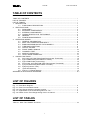
Fig. 3.1: Organization of the threshold registers T0..T15............................................................. 9
Fig. 3.2: Pattern for the Time Range setting of the i-th channel................................................... 9
LIST OF TABLES
Table 4.1: Mod. C207 CAMAC Functions ................................................................................... 12
i
25/01/96
1.
C207 User's Manual
DESCRIPTION
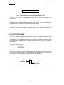
1.1. FUNCTIONAL DESCRIPTION
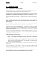
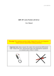
The CAEN Model C207 is a 16 CHANNEL PROGRAMMABLE DISCRIMINATOR housed in a
1-unit wide CAMAC module (a functional block diagram is shown in Fig. 1.1).
The module accepts 16 negative inputs via 16 front panel LEMO 00 type connectors (INPUTS 0
to 15) and produces 16 differential ECL outputs (with a FAN-OUT of two for each channel) that
are available on two front panel flat cable connectors (OUTPUTS 0 to 15 A and B).
Each channel consists of a discriminator on a hybrid circuit and an 8-bit DAC for the threshold
setting.
The Timing Stage of the discriminator works in UPDATING mode. It produces an output pulse
whose width is independent from the input signal time over threshold and adjustable in two
ranges via the front panel common trimmer WDT (16 internal jumpers, one per channel, allow
the range setting).
The module's operations can be controlled either via CAMAC or locally. A front panel "LOC"
LED indicates when lit that the module is controllable locally. A back panel switch disables the
REMOTE operations and sets the module in LOCAL mode ("LOC" LED is ON).
Each channel has its own discriminating threshold programmable via CAMAC, and can be
turned on or off via CAMAC by using a mask Register (Pattern of Inhibit). The thresholds can
be set in a range from 0 mV to -510 mV (-2 mV step), though for proper functioning a minimum
threshold of -6 mV is required.
In LOCAL mode a common threshold can be set and monitored respectively via front panel
trimmer and test point. Moreover, the Pattern of Inhibit is disabled (all channels are enabled)
and the CAMAC functions are ineffective.
Some operations can be also performed using two external NIM signals (indicated on the back
panel connectors with "VETO" and "TEST"):
• VETO: an input signal sent through this connector allows vetoing of all channels
simultaneously. A veto pulse of width T will veto the input during this time T.
• TEST: a pulse sent through this connector triggers all the enabled channels at once (all
channels in LOCAL mode). This useful feature allows a complete test of the module
without removing any input cable as well as it allows generation of a pattern of pulses
suitable to test any following electronics.
These are high impedance inputs and each one is provided with two bridged connectors for
daisy chaining.
On the front panel there is also available a Current Sum output that generates a current
proportional to the input multiplicity, i. e. to the number of channels over threshold, at a rate of
−1.0 mA per hit (-50 mV per hit into a 50 Ω load) ±10%.
An "OR" output signal on a front panel connector provides a global OR of the Shaped Outputs.
An "OR" LED lights up if at least one of the unmasked channels is over threshold.
1
25/01/96
C207 User's Manual
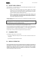
DAC,TEST,
INHIBIT
R/W LOGIC
........................
test
THR
8 bit
DAC
8 bit
DAC ..................
8 bit
DAC
8 bit
DAC
ch.0
ch.1
ch14
ch.15
inhibit
THRESHOLDS
CAMAC
INTERFACE
INPUTS<0..15>
OR LED
WDT
hybrid
discr.
hybrid
hybrid
discr. ................. discr.
ch.0&1
ch.2&3
ch.12&13
hybrid
discr.
ch.14&15
TEST
VETO
OUTPUTS<0..15>
OR OUT
Fig. 1.1: C207 Block Diagram
2
25/01/96
2.
C207 User's Manual
SPECIFICATIONS
2.1. PACKAGING
1-unit wide CAMAC module.
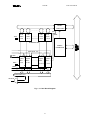
2.2. EXTERNAL COMPONENTS
CONNECTORS:
- No. 16, "INPUT 0..15", LEMO 00 type. These are the connectors for the input signals.
- No. 2, "OUTPUTS 0..15 A, B", double row strip header, 17+17 pin. These connectors
deliver the output signals.
- No. 1, "Σ", LEMO 00 type. It delivers a current proportional to the input multiplicity, i. e.
to the number of channels over threshold, at the rate of -1.0 mA per hit (-50 mV per hit
into 50 Ω load) ±10%.
- No. 1, "OR", LEMO 00 type. It provides a signal that is the OR of the Output shaped
signals.
- No. 2, "VETO", LEMO 00 type. These are the back panel connectors for the veto input
signal that can be daisy chained.
- No. 2, "TEST", LEMO 00 type. These are the back panel connectors for the test input
signal that can be daisy chained.
DISPLAYS:
- No. 1, "LOC", red LED, lit up if the module is in LOCAL mode.
- No. 1, "OR", green LED, lit up if at least one channel is over threshold.
TRIMMERS, SWITCHES:
- No. 1, "WDT", screw-driver trimmer, for the common output signals width adjustment.
- No. 1, "THR", screw-driver trimmer, for the common threshold adjustment in LOCAL
mode.
- No. 1, "REM/LOC", back panel switch, for the operating mode (REMOTE or LOCAL)
selection.
TEST POINTS:
- No. 1, "THR", test point, for the common threshold monitoring.
3
25/01/96
C207 User's Manual
2.3. INTERNAL COMPONENTS
CONNECTORS:
- No. 16, "JP1-JP16 (LTi-STi)", Jumpers, for the width range selection.
2.4. CHARACTERISTICS OF THE SIGNALS
INPUTS:
- INPUT CHANNELS: negative polarity, 50 Ω impedance;
maximum absolute ratings: ± 5 Volts;
input offset voltage: ± 5 mV;
reflections < 4% for 2 ns risetime pulses.
- THRESHOLD:
-6 mV to -510 mV, 2 mV step in programmable mode,
continuous set in Local mode via front panel trimmer;
monitor test point on front panel with range +6 mV to +510 mV.
- VETO(*):
std. NIM level, high impedance;
minimum width: 10 ns;
veto leading edge must precede of at least 7 ns the input leading
edge and overlap completely the input signal.
- TEST(*):
std. NIM level, high impedance;
maximum frequency: 125 MHz;
minimum width: 5 ns.
(*) These inputs are at high impedance and each one is provided with two bridged connectors for daisy
chaining. Note that the high impedance makes these inputs sensitive to noise, so the chains have to be
terminated on 50 Ω on the last module; the same is needed also if one module only is used, whose inputs
have thus to be properly matched.
OUTPUTS:
- CHANNELS:
differential ECL level into 110 Ω twisted-pair;
pulse width continuously adjustable via trimmer in two ranges:
• 4 - 40 ns (approx.);
• 40 - 300 ns (approx.);
range selection via internal jumpers;
Input/Output delay: 8 ±1 ns;
Test/Output delay: 13 ns;
Risetimes and Falltimes: < 3 ns.
- CURRENT SUM (Σ): high impedance current source;
current proportional to the input multiplicity;
rate: -1.0 mA per hit (-50 mV/hit into a 50 Ω load) ±14%
offset: -60 mV approx. (no channel over threshold).
4
25/01/96
2.5. GENERAL
Double pulse resolution: 7.5 ns.
Maximum frequency: 125 MHz.
Interchannel isolation: better than 50 dB.
Time slewing < 400 ps for input amplitudes from 2x to 20x over threshold.
2.6. POWER REQUIREMENTS
- 24 V
+ 12 V
- 12 V
+6V
-6V
25 mA
15 mA
30 mA
500 mA
3.4 A
5
C207 User's Manual
25/01/96
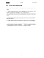
C207 User's Manual
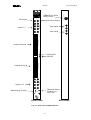
16 CH
PROGRAMMABLE
DISCRIMINATOR
OR Output
Inputs 0..7
OR
R
E
M
REMOTE or LOCAL
SELECTION
Mod. C207
Σ
Current Sum Output
6
7
4
5
I
N
P
U
T
2
3
0
1
+
−
L
O
C
Test Inputs
T
E
S
T
Veto Inputs
V
E
T
O
0
O
U
T
P
U
T
Outputs Group A
L
15 O
C
0
LOCAL LED
OR LED
O
R
O
U
T
P
U
T
Outputs Group B
15
Inputs 8..15
+
−
14
15
12
13
10
11
8
Width setting Trimmer
I
N
P
U
T
Threshold setting
Trimmer and
Test Point
9
THR
WDT
FRONT PANEL
BACK PANEL
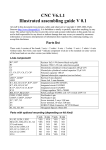
Fig. 2.1: C207 Front and Back Panels
6
25/01/96
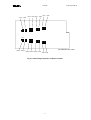
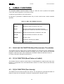
CH1
CH0
CH3 CH2
CH5
CH4
C207 User's Manual
CH7 CH6
ST1
ST14
CH14 CH15
SOLDERINGS SIDE VIEW
CH12 CH13
CH10 CH11 CH8 CH9
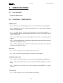
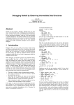
Fig. 2.2: C207 Range Selection Jumpers Location
7
25/01/96
3.
C207 User's Manual
OPERATING MODES
3.1. GENERAL INFORMATION
The CAEN Model C207 is a 16 CHANNEL PROGRAMMABLE DISCRIMINATOR
housed in a 1-unit wide CAMAC module.
The module accepts 16 negative inputs via 16 front panel LEMO 00 type connectors
(INPUTS 0 to 15) and produces 16 differential ECL outputs (with a FAN-OUT of two for
each channel) that are available on two front panel flat cable connectors (OUTPUTS 0 to
15 A and B).
Paragraphs 3.2 to 3.8 describe the various operations that can be done via CAMAC in
order to use the C207 module in REMOTE mode. Paragraph 3.9 describes the
operations that can be done in order to use the C207 module in LOCAL mode.
3.2. MOD. C207 POWER-ON AND RESET
With the back panel switch in the "REM" position the module is in REMOTE mode. At
Power-On the contents of the Pattern of Inhibit and Threshold Registers are not
determined. A reset of the module and a setting of the Registers must be performed
before any other operation.
It is possible to reset the C207 by performing a C, Z command or a F(9) N CAMAC
Function. After this operation, the C207 is initialized; this causes the following:
- all channels are enabled (all bits of the Pattern of Inhibit are set to 1);
- the Q response on the F(2) N Function is cleared.
The RESET operation doesn’t affect the content of the Threshold Registers.
3.3. ENABLING/DISABLING OF THE CHANNELS
The User can enable or disable each of the 16 channels via CAMAC by performing a
F(17) N CAMAC Function with the Write Lines W1-W16 set to 1 or 0 according to the
chosen configuration (16 bit Pattern of Inhibit). A channel is enabled if the corresponding
bit of the Pattern is high (e. g., bin. 0000000000001100, or hex 000C, enables channels
2 and 3 of the discriminator).
A F(1) N CAMAC Function allows to read out the Pattern of Inhibit configuration.
It is also possible to inhibit all channels via a CAMAC I (Inhibit) operation. The CAMAC
Inhibit has no effect on the TEST input or the F(25) CAMAC Function.
3.4. THRESHOLDS SETTING
The discriminating thresholds can be programmed in a range from 0 mV to -510 mV in
steps of −2 mV, though for proper functioning a minimum threshold of -6 mV is required.
It is possible to set, via CAMAC, independent thresholds for each channel; 16 eight bit
registers (T0..T15) are accessible via CAMAC for the thresholds setting and monitoring.
The structure of these registers is shown in the following figure.
8
25/01/96
7
6
C207 User's Manual
5 4 3 2 1
Threshold channel n
0
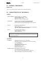
Fig. 3.1: Organization of the threshold registers T0..T15
The bits <7..0> show the threshold absolute value of the channels; the weight of the
LSB is -2 mV.
In order to write the thresholds for each channel, the User must perform a F(16) N A(i)
CAMAC Function, where subaddress i selects the i-th channel. The chosen value of the
thresholds must be present on the CAMAC Write lines W1-W8.
The thresholds can be read back for each channel: the User must perform a F(0) N A(i)
CAMAC Function, where subaddress i selects the i-th channel. The chosen value of the
thresholds is present on the CAMAC Read lines R1-R8.
3.5. OUTPUT PULSES
The width of the output signals does not depend on the time over threshold of the input
signals. The front panel trimmer "WDT" allows a common manual adjustment of the
output pulses. It is possible, for each channel, to have two adjustment ranges by setting
the corresponding jumpers (JP1 to JP16) as previously shown in Fig 2.2 for the short
range setting.
The two selectable ranges are:
- 4 ns - 40 ns;
- 40 ns - 300 ns.
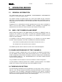
The position of the jumpers can also be deducted from the solderings side of the board:
the layout of the board contains a printed pattern with indications on Short Time (ST) or
Long Time (LT) setting for the i-th channel (see fig. 3.2). The jumper has to short circuit
the middle pin hole with the desired external pin hole as in Figure 3.2.
Long Time
Selection
LTi
Short Time
Selection
STi
Fig. 3.2: Pattern for the Time Range setting of the i-th channel
9
25/01/96
C207 User's Manual
3.6. FRONT PANEL SIGNALS
Some operations can be performed by two external NIM signals (indicated on the back
panel connectors with "VETO", "TEST"):
• TEST: an input signal sent through this connector triggers all the enabled
channels at once. This useful feature allows a complete test of the module
without removing any input cable as well as it allows generation of a pattern
of pulses suitable to test any following electronics.
• VETO: an input signal sent through this connector allows vetoing of all
channels simultaneously. A veto pulse of width T will veto the input during this
time T. Its leading edge must precede the input leading edge by at least 7 ns
and overlap completely the input signal.
These are high impedance inputs and each one is provided with two bridged connectors
for daisy chaining.
Note that the high impedance makes these inputs sensitive to noise, so the chain has to
be terminated on 50 Ω on the last module; the same is needed also if one module only is
used, whose inputs have thus to be properly matched.
The VETO has no effect on the TEST input or the F(25) CAMAC Function.
On the front panel there is also available a Current Sum output connector that generates
a current proportional to the input signal multiplicity, i. e. to the number of channels over
threshold, at a rate of -1.0 mA per hit (-50 mV per hit into a 50 Ω load) ±10%.
An OR output connector provides the Logical OR of the Output channels.
3.7. CHANNELS TEST
It is possible to obtain pulses on all channels:
• by sending a NIM pulse through one of the two "TEST" connectors located on the
front panel.
• by performing a F(25) N CAMAC Function.
3.8. MODULE OPERATION
Once the thresholds are set and the desired channels are enabled via the Pattern of
Inhibit Register, the module is ready to operate. All inputs exceeding the threshold value
will produce an output pulse of width that can be set via front panel trimmer. A F(2) N
CAMAC Function tests the activity of the module: if at least one of the unmasked
channels is over threshold, this Function returns a Q=1 value (see 4.3). This Function
clears automatically the status of the Q line.
10
25/01/96
C207 User's Manual
3.9. LOCAL MODE OPERATION
With the back panel switch in the "LOC" position the module is in LOCAL mode ("LOC"
LED is ON). At Power-On the bits of the Pattern of Inhibit and Threshold Registers are
all set to 1: all channels are enabled but the thresholds of the Threshold Register are not
active.
A common threshold must be set via front panel trimmer. A front panel test point
provides a monitoring of the threshold in a range +6 mV to +512 mV.
Once the threshold is set the module is ready to operate. All inputs exceeding the
threshold value will produce an output pulse of width that can be set via front panel
trimmer.
In LOCAL mode the CAMAC readout of the Pattern of Inhibit and Threshold Registers
(F(0) N A(0-15), F(1) N Functions) is active (all bits must be 1, otherwise the module is
not working correctly).
If the User switches the module from REMOTE to LOCAL while it is still powered, the
module will behave as above: the bits of the Pattern of Inhibit and Threshold Registers
are all set to 1.
If the User switches the module from LOCAL to REMOTE while it is still powered, the
module will maintain its registers configuration, i. e., the bits of the Pattern of Inhibit and
Threshold Registers are still set to 1 and need to be set again via CAMAC.
11
25/01/96
4.
C207 User's Manual
CAMAC FUNCTIONS
The standard CAMAC Functions listed in Table 4.1 allow the user to perform the required
control and readout operations on the C207 module.
X response is generated for each valid function.
Q response is generated in REMOTE Mode only for each valid function unless otherwise
specified.
Table 4.1: Mod. C207 CAMAC Functions
F(0) N A(0-15) *
Reads the Discriminator Thresholds on R1..R8.
F(1) N *
Reads the Pattern of Inhibit on R1..R16.
F(2) N
Tests the module activity and clears the Q line.
Q response if at least one channel is over threshold.
F(16) N A(0-15)
Writes the Discriminator Thresholds on W1..W8.
F(17) N
Writes the Pattern of Inhibit on W1..W16.
F(25) N
Common Test.
I
Vetoes the channels via CAMAC.
F(9) N, C, Z
Resets the module
*: Q response also in LOCAL mode.
4.1. F(0) N A(0-15) FUNCTION (Read Discriminator Thresholds)
This CAMAC Function reads the 8 bit Threshold Register (on read lines R1-R8); subaddresses
0 through 15 select the different channels (0 through 15). For each channel the Threshold
Register contains the value of the threshold set via CAMAC. Read lines R9-R16 are set to 1.
In LOCAL mode the R1-R16 lines are all set to 1.
4.2. F(1) N FUNCTION (Read Pattern of Inhibit)
This CAMAC Function reads the 16 bit Pattern of Inhibit Register (on read lines R1-R16); each
bit set to 1 corresponds to an active Discriminator channel. In LOCAL mode the R1-R16 lines
are all set to 1.
4.3. F(2) N FUNCTION (Test Activity)
This CAMAC Function tests the status of the Q line. The Q response is generated and held if at
least one channel is over threshold. The Q line is cleared with the F(2) N Function.
12
25/01/96
C207 User's Manual
4.4. F(16) N A(0-15) FUNCTION (Write Discriminator
Thresholds)
This CAMAC Function writes in the 8 bit Threshold Register (via write lines W1-W8);
subaddresses 0 through 15 select the different channels (0 through 15). For each channel the
Threshold Register contains the value of the threshold and it can be read via CAMAC (F(0) N
A(0-15)Function).
4.5. F(17) N FUNCTION (Write Pattern of Inhibit)
This CAMAC Function writes the 16 bit Pattern of Inhibit Register (via write lines W1-W16);
each bit set to 1 corresponds to an active Discriminator channel.
4.6. F(25) N (Common Test)
This CAMAC Function allows the testing of the module; it triggers all discriminator outputs at
once.
4.7. I (Veto All Channels)
This CAMAC Function vetoes all channels. It has no effect on the TEST input or the F(25) N
Function.
4.8. F(9) N, C, Z (Reset Module)
This CAMAC Function resets the module; this causes the following:
- the Pattern of Inhibit bits are set to 1 (all channels enabled);
- the Q response on F(2) N is cleared.
13
25/01/96
APPENDIX A: ELECTRICAL DIAGRAMS
A.1
C207 User's Manual
conditions or ope
caused by mish
declares that the
CAEN will repa