1
SSD Parvex SAS
8, avenue du Lac - B.P. 249
F-21007 Dijon Cedex
www.SSDdrives.com
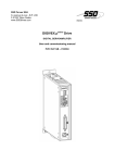
DIGIVEX Power Motion
Digital servoamplifier
User and commissioning manual
PVD 3522 GB – 04/2004
PRODUCT RANGE
1-
« BRUSHLESS » SERVODRIVES
TORQUE OR POWER
RANGES
•
•
•
2-
BRUSHLESS SERVOMOTORS, LOW INERTIA, WITH RESOLVER
Very high torque/inertia ratio (high dynamic performance machinery):
⇒ NX -HX - HXA
⇒ NX - LX
High rotor inertia for better inertia load matching:
⇒ HS - LS
Varied geometrical choice :
⇒ short motors range HS - LS
⇒ or small diameter motors : HD, LD
Voltages to suit different mains supplies :
⇒ 230V
three-phase for «série L - NX»
⇒ 400V, 460V three-phase for «série H - NX»
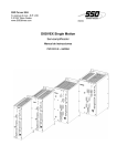
"DIGIVEX Drive" DIGITAL SERVOAMPLIFIERS
⇒ SINGLE-AXIS
DSD
⇒ COMPACT SINGLE-AXIS
DµD, DLD
⇒ POWER SINGLE-AXIS
DPD
⇒ MULTIPLE-AXIS
DMD
"PARVEX MOTION EXPLORER" ADJUSTING SOFTWARE
1 to 320 N.m
0,45 to 64 N.m
3,3 to 31 N.m
3,3 to 31 N.m
9 to 100 N.m
SPINDLE DRIVES
•
•
3-
SPINDLE SYNCHRONOUS MOTORS
⇒ "HV" COMPACT SERIES
⇒ "HW" ELECTROSPINDLE,frameless, water-cooled motor
From 5 to 110 kW
up to 60,000 rpm
"DIGIVEX" DIGITAL SERVOAMPLIFIERS
DC SERVODRIVES
•
•
•
4-
"AXEM", "RS" SERIES SERVOMOTORS
"RTS" SERVOAMPLIFIERS
"RTE" SERVOAMPLIFIERS for DC motors + resolver giving position
measurement
0.08 to 13 N.m
SPECIAL ADAPTATION SERVODRIVES
•
•
5-
"EX" SERVOMOTORS for explosive atmosphere
"AXL" COMPACT SERIES SERVOREDUCERS
POSITIONING SYSTEMS
•
•
•
•
Numerical Controls « CYBER 4000 » 1 to 4 axes
"CYBER 2000" NC 1 to 2 axes
VARIABLE SPEED DRIVE - POSITIONER
⇒ SINGLE-AXIS
DSM
⇒ POWER SINGLE-AXIS
DPM
⇒ MULTIPLE-AXIS
MM
ADJUSTMENT AND PROGRAMMING SOFTWARE PARVEX MOTION EXPLORER
5 to 700 N.m
DIGIVEX Power Motion Servoamplifier
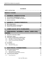
CONTENTS
SAFETY INSTRUCTIONS
…………………………………………………………………………… 4
PRODUCT RANGE
2
1. GENERAL PRESENTATION
6
1.1
1.2
1.3
List of published DIGIVEX Motion manuals
General Concepts of «DIGIVEX Power Motion»
System components
2. GENERAL CHARACTERISTICS
2.1
2.2
2.3
Mains characteristics
Servoamplifier General Characteristics
General characteristics of the DPM
6
6
7
9
9
9
10
3. COMPLIANCE WITH STANDARDS
11
4. DIMENSIONS, ASSEMBLY, MASS, LABELLING,
CODING
12
4.1 Dimensions, Assembly and Mass
4.2 Labeling and coding
4.3 Front panel, terminal blocks and SUB-D plugs
4.3.1
Description of terminal blocks and sockets
4.3.2
Description of 7-segment display and LEDs
4.3.3
Rotary mini-switch setting (ADDRESS)
4.3.4
Diagrams
4.4 Accessories
4.4.1
Input mains filter
4.4.2
Inductors for long cables
5. ELECTRICAL CONNECTIONS
5.1 General Wiring Requirements
5.1.1
Appliance handling
5.1.2
Electromagnetic compatibility
5.1.3
DIGIVEX Power Motion Sub-D connectors
5.2 Typical Connection Diagram
5.2.1
Surge Suppressor
1
PVD 3522 GB 04/2004
12
16
18
18
19
19
20
24
24
24
31
31
31
31
32
32
36
DIGIVEX Power Motion Servoamplifier
5.3 Power component dimensioning
5.4 MAIN SUPPLY Connection (Terminal block B1)
5.5 Auxiliary supply Connection (Terminal block B2)
5.6 Brake Supply Connection (Terminal block B3)
5.7 Earth connection
5.8 Short-circuit capability
5.9 Motor end connection
5.9.1
Terminal block B4 and B5
5.9.2
Motor Power connection
5.9.3
Terminal block connection
5.9.4
Power connector connection
5.9.5
"POWER" Cable Definition
5.9.6
Guidelines for long cables between the motor and drive
5.9.7
Holding Brake Connection
5.9.8
Thermal protection Connection
5.9.9
Motor Ventilation Connection
5.10
Automatic control Input / Output connection
5.10.1 Terminal block B6 and B7
5.10.2 main contactor control
5.11
Resolver Connection
5.11.1 Description
5.11.2 Sub-D connector X4:"Resolver"
5.11.3 Cables
5.12
FIELDBUS Connections
5.12.1 SUB-D X1 plug : FIELDBUS
5.12.2 CANopen connections and cables
5.12.3 Profibus connections and cables
5.13
Input/Output connection
5.13.1 SUB-D X2 socket: Inputs/Outputs
5.13.2 Input/Output characteristics
5.13.2.1
Logic outputs (out0 - out7)
5.13.2.2
Analogue output (outa)
5.13.2.3
Logic inputs (in0 - in 15)
5.13.2.4
Analogue input (ina)
5.13.3 Cable
5.14
Encoder emulation option connection (SC6639)
5.14.1 Description
5.14.2 Sub-D connector X3: encoder emulation option
5.14.3 Programming resolution and zero mark position
5.14.4 Electrical characteristics
5.14.5 Cable
5.15
External encoder input option connection (SC6638)
2
PVD 3522 GB 04/2004
37
37
38
38
39
39
39
39
40
40
41
42
43
44
44
44
45
45
46
47
47
48
48
50
50
50
50
51
51
52
52
52
53
54
54
56
56
56
57
57
59
61
DIGIVEX Power Motion Servoamplifier
5.15.1
5.15.2
5.15.3
5.16
5.16.1
5.16.2
5.16.3
Description
SUB-D X3 sockets: encoder input option
Cable
Connecting the SinCos encoder input option (SC6645)
Description
SUB-D X3 plug: Encoder input option.
Cables
6. COMMISSIONING - DIAGNOSTICS
6.1 Start Up Sequence
6.1.1
Prior Checks
6.1.2
Commissioning with PME-DIGIVEX Motion
6.2 Initialization Sequence
6.3 Stop Sequence
6.3.1
Description of stop sequence times
6.3.2
Stop due to removal of mains
6.3.3
Stop following a fault on mains side
6.3.4
Stop following a fault on motor side
6.4 Detecting Reasons for Stoppage
6.4.1
LED display - power supply function
6.4.2
Current Monitoring
6.4.3
Temperature Monitoring
6.4.4
7-segment display status
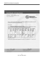
7. UL CERTIFICATE
61
62
62
66
66
67
67
69
69
69
69
70
70
71
71
71
71
72
72
73
74
75
76
Characteristics and dimensions subject to change without notice.
YOUR LOCAL CORRESPONDENT
SSD Parvex SAS
8 Avenue du Lac / B.P 249 / F-21007 Dijon Cedex
Tél. : +33 (0)3 80 42 41 40 / Fax : +33 (0)3 80 42 41 23
www.SSDdrives.com
3
PVD 3522 GB 04/2004
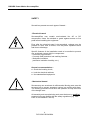
DIGIVEX Power Motion Servoamplifier
SAFETY
Servodrives present two main types of hazard :
- Electrical hazard
Servoamplifiers may contain non-insulated live AC or DC
components. Users are advised to guard against access to live
parts before installing the equipment.
Even after the electrical panel is de-energized, voltages may be
present for more than a minute, until the power capacitors have
had time to discharge.
Specific features of the installation need to be studied to prevent
any accidental contact with live components :
- Connector lug protection ;
- Correctly fitted protection and earthing features ;
- Workplace insulation
(enclosure insulation humidity, etc.).
General recommendations :
• Check the bonding circuit;
• Lock the electrical cabinets;
• Use standardised equipment.
- Mechanical hazard
Servomotors can accelerate in milliseconds. Moving parts must be
screened off to prevent operators coming into contact with them.
The working procedure must allow the operator to keep well clear
of the danger area.
All assembly and commissioning work must be done by qualified
personnel who are familiar with the safety regulations (e.g. VDE
0105 or accreditation C18510).
4
PVD 3522 GB 04/2004
DIGIVEX Power Motion Servoamplifier
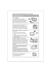
Upon delivery
All servoamplifiers are thoroughly inspected during manufacture and tested at length before
shipment.
•
•
Unpack the servoamplifier carefully and check it is in good condition.
Also check that data on the manufacturer's plate complies with data on the order
acknowledgement.
If equipment has been damaged during transport, the addressee must file a complaint with the
carrier by recorded delivery mail within 24 hours.
Caution :
The packaging may contain essential documents or accessories, in particular :
• User Manual,
• Connectors.
Storage
Until installed, the servoamplifier must be stored in a dry place safe from sudden temperature
changes so condensation cannot form.
Special instructions for setting up the equipment
CAUTION
For this equipment to work correctly and safely it must be
transported, stored, installed and assembled in accordance with
this manual and must receive thorough care and attention.
Failure to comply with these safety instructions may lead to
serious injury or damage.
The cards contain components that are sensitive to electrostatic
discharges. Before touching a card you must get rid of the static
electricity on your body. The simplest way to do this is to touch a
conductive object that is connected to earth (e.g. bare metal
parts of equipment cabinets or earth pins of plugs).
5
PVD 3522 GB 04/2004
DIGIVEX Power Motion Servoamplifier
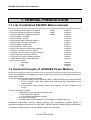
1. GENERAL PRESENTATION
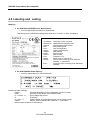
1.1 List of published DIGIVEX Motion manuals
♦
♦
♦
♦
♦
♦
♦
♦
♦
♦
♦
♦
♦
♦
♦
♦
DIGIVEX Single Motion (DSM) User Manual
DIGIVEX Power Motion (DPM) User Manual
DIGIVEX Multi Motion (DMM) User Manual
DIGIVEX Motion - CANopen
DIGIVEX Motion - Profibus
PME-DIGIVEX Motion Adjustment Manual
DIGIVEX Motion Directory of Variables
DIGIVEX Motion Programming
DIGIVEX Motion - Cam Function
PME Tool kit User and Commissioning Manual
CANopen - CAN Bus Access via CIM03
CANopen - Remote control using PDO messages
"Block Positioning" Application Software
"Fly shear linear cutting" software application
"Rotary blade cutting" software application
Motor user's manuals:
◊ HX/HS/HD
◊ NX
◊ HW
(DSM)
(DPM)
(DMM)
PVD3515
PVD3522
PVD3523
PVD3518
PVD3554
PVD3516
PVD3527
PVD3517
PVD3538
PVD3528
PVD3533
PVD3543
PVD3519
PVD3531
PVD3532
PVD3490
PVD3535
PVD3496
1.2 General Concepts of «DIGIVEX Power Motion»
"DPM" servoamplifiers are designed to control magnet-type synchronous brushless motors from
the NX and H ranges.
A box-type electronic control system including :
♦ A power supply function with direct 400V or 480V/50-60Hz mains input and 550V
DC bus voltage output This module also controls energy regeneration to the
mains network..
♦ A servomotor control function (power and resolver), for axis or spindle drive
motors.
They are designed to provide:
• positioning or synchronization functions from,
♦ either the motor resolver,
♦ or an external incremental encoder
• plc-type logic functions
• message or parameter transfers via a CANopen or Profibus field bus.
Parameters specification (current, speed, position) and programming (pseudo BASIC or
applicative programs) are done by PC with "PME - DIGIVEX Motion" software (under WINDOWS).
A 7-segment display provides a direct readout of the main drive status.
6
PVD 3522 GB 04/2004
DIGIVEX Power Motion Servoamplifier
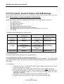
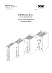
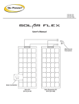
1.3 System components
A DPM drive system comprises as a minimum:
• A DPM drive-positioner, 480V three-phase, or 400 V three-phase supply depending on
the product number
• A mains filter for compliance with CE requirements
• An H or NX series (400V/460V supply) brushless motor with a resolver-type position
sensor and thermal protective sensor. The motor may be equipped with a brake (see
motor code).
• An auxiliary AUX power supply for the regulation section of the DPM,
• A control unit for activating the stored programs via DPM inputs / outputs (contacts, push
buttons, and possibly an external plc).
It may also feature:
• Additive chokes located close to the drive between the motor and drive where long cables
are used.
• An option
♦ "external encoder input" for "master-slave" type operations or for applications
requiring position acknowledgement on the machine and not the motor.
OR
♦ "encoder emulation output" (with resolution adjustable from 1 to 16,384 marks
per revolution).
• A µVision terminal for displaying messages or entering digital values (µVision terminal
connected to drive via a CANopen type bus).
• Connection cables (supplied by Parvex).
Regulation parameter specification, drive setting and user program entry or modification is done
exclusively by PC with PME-DIGIVEX Motion software.
The drives are fitted, depending on the reference, with CANopen (DPMxxxxxC) or Profibus
(DPMxxxxxP) communication inputs as standard.
7
PVD 3522 GB 04/2004
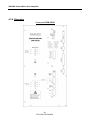
DIGIVEX Power Motion Servoamplifier
Mains
filter
Optional line
chokes
H-series
motor
Power
supply
Thermal
Auxiliary supply AUX
Brake
Logic inputs
Resolver
Logic outputs
PLC
Analogue
inputs
Analogue
outputs
Option :
• external encoder input
Or
• encoder emulator output
CANopen or Profibus
8
PVD 3522 GB 04/2004
DIGIVEX Power Motion Servoamplifier
2. GENERAL CHARACTERISTICS
2.1 Mains characteristics
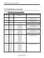
DIGIVEX Power Motion
RATING Ô
Frequency
Minimum voltage
Maximum voltage
Usual voltage
Rated rms current
Direct voltage Gleichspannung
DPM 50/80
DPM 100/120
DPM 150
48 to 62 Hz
200 V rms.
530 V rms
400/480 V +/- 10%
64 A
100 A
270 to 750 V
32 A
DPM 200
DPM 300
130A
200A
The system can be operated with 230V rms mains supply but the speeds and powers shown in the
motor/servoamplifier characteristics are no longer achieved.
An external mains filter is required for compliance with electromagnetic compatibility requirements.
The DIGIVEX Power Motion supply features IGBT transistors. Braking energy is returned to the mains
supply.
Mains monitoring :
• no phase,
• overcurrent.
• Voltage between phases too great
2.2 Servoamplifier General Characteristics
TYPE
DPM 50/80
DPM 100/120
DPM 150
DPM 200
DPM 300
MAINS
400/480 V 3ph
50/60 Hz
Max 480 + 10%
400/480 V 3ph
50/60 Hz
Max 480 + 10%
400/480 V 3ph
50/60 Hz
Max 480 + 10%
400/480 V 3ph
50/60 Hz
Max 480 + 10%
400/480 V 3ph
50/60 Hz
Max 480 + 10%
BUS
CONTROLLABLE
RATED
POWER
VOLTAGE
BRAKING
CAPACITY BY
REGENERATION
TO NETWORK
PEAK
PERMANENT
CURRENT
PEAK
PULSE
CURRENT
550 V
20 kW
20 kW
50 A
80 A
550 V
40 kW
40 kW
100 A
120 A
550 V
60 kW
60 kW
150 A
150 A
550 V
80 kW
80 kW
200 A
200 A
550 V
120 kW
120 kW
300 A
300 A
(*) UL and c UL required: Power is limited to 16kW
An external fan is required to achieve the stated performances for the DPM 200 and 300 (see Section
4.4 "Accessories")
9
PVD 3522 GB 04/2004
DIGIVEX Power Motion Servoamplifier
DPM 50/80
DPM 100/120
DPM 150
DPM 200
DPM 300
POWER DISSIPATED IN KW
0,7
1
1,2
1,6
2,4
LOW-LEVEL CONSUMPTION IN W
35
40
45
75
100
2.3 General characteristics of the DPM
Power reduction with altitude
Above 1000 m, service power falls by 1% for every 100 m up
to a maximum altitude of 4000 m
Normal use: 0 - 40°C
Operating temperature
Above 40°C, service power fall by 20% for every 10°C up to a
maximum temperature of 60°C.
Drive stops when ambient temperature is higher than 60°C
relative humidity
85% (without condensation)
Storage temperature
-30°C to +85°C
Chopping frequency
50/80 and 100/120 : 8kHz
Current bandwidth
600Hz to -3dB
Speed bandwidth
Up to 60Hz
Maximum speed
Driven by DIGIVEX : 60,000 rpm
Galvanic insulation of power bridge
Mean current protection in line with drive calibre
Pulse current protection of drive and motor
Rms current protection of motor
Protection against short circuits at bridge output
Mains network overvoltage
Electrical protection
Mechanical protection
IP20 under IEC 529
Pollution degree
UL: 2: enclosure mounting
Tracking error
Motor temperature
Other monitoring
Drive temperature
No resolver
Brake supply
Limit switches
User programs
Memory sizes
FLASH_DM :
PROG_DM :
512 Kilobyte
256 Kilobyte
Communication bus:
• CANopen:
DPMxxxxxC reference positioner drives
DPMxxxxxP reference positioner drives
• Profibus:
10
PVD 3522 GB 04/2004
150-200-300 : 4KHz
DIGIVEX Power Motion Servoamplifier
3. COMPLIANCE WITH STANDARDS
DIGIVEX Power Motion
The CE mark of this product is affixed to the front panel (silk-screen printing).
The DIGIVEX Power Motion 100/120, 150, 200, and 300 have the CE marking under the
European Directive 89/336/EEC as amended by Directive 93/68/EEC on electromagnetic
compatibility as well as under the Electrical Safety Directive of Low Voltage Directive 73/23/EEC
amended by Directive no. 93/68/EEC.
The European Directive concerning electromagnetic compatibility refers to the harmonised generic
standards EN 50081-2 of December 1993 (Electrical Compatibility - Generic Standard for
Emissions - Industrial Environments) and EN 50082-2 of June 1995 (Electromagnetic
Compatibility - Generic Standard for Immunity – Industrial Environments). These two harmonised
generic standards are based on the following standards:
- EN 55011 of July 1991: Radiated and conducted emissions.
- ENV 50140 of August 1993 and ENV 50204: Immunity to radiated electromagnetic
fields.
- EN 61000-4-8 of February 1994: Mains frequency magnetic fields.
- EN 61000-4-2 of June 1995: Electrostatic discharge.
- ENV 50141 of August 1993: Interference induced in cables.
- EN 61000-4-4 of June 1995: Rapid transient.
The Low Voltage Directive groups all the electrical safety standards together including the EN
60204-1 Standard which covers electrical fittings on industrial machinery.
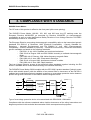
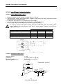
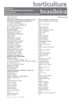
The DIGIVEX Power Motion 50/80 complies with the CEI 1800-3 product standard ("electric power
drives with variable speed") with the addition of an external filter in observance of the EN 55011
(radiated and conducted emissions) standard as well as an overvoltage protective device between
phases and ground connection in accordance with the diagram below:
fuses
power
L1
L2
L3
Overvoltage
protective
device
Filter
FR03636
EP
to
DPM
EP
auxiliary
Type of overvoltage protective device to be associated with DPM 50/80: 15KA/440V
Compliance with the reference standards above implies observance of the wiring instructions and
diagrams provided in this technical documentation which accompanies all equipment.
11
PVD 3522 GB 04/2004
DIGIVEX Power Motion Servoamplifier
Incorporation in a machine
The design of this equipment allows it to be used in a machine subject to Directive 98/3 7/EC of
22/06/98 (Machinery Directive), provided that its integration (or incorporation and/or assembly) is
done in accordance with trade practices by the machine manufacturer and in accordance with the
instructions in this booklet.
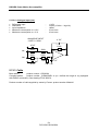
UL and c UL conformity
The DIGIVEX Power Motion 50/80 product is certified UL and c UL with the following operating
characteristics:
Main voltage
400V
480V
Input
(Arms)
32A
30A
current Continuous
power
16 kW
18 kW
output
(see certificate chapter 7).
Electromagnetic compatibility
The CEI 1800-3 ("electric power drives with variable speed") standard defines the compatibility
criteria that have to be observed by an electronic device in an industrial environment. Please find
below several important points concerning the harmonic emission rate for drives and the
impedance for the mains network to which it is connected.
Harmonic levels
The harmonic content of the mains network currents varies depending on whether the drive
consumes power or whether it returns energy to the mains supply. When the drive issues rated
voltage, the level of harmonic distortion
( THD=
Ieff ² − Ih1²
Ih1
)
is approx. 50%. Contrarily, if the
drive returns its rated voltage to the mains supply, the "THD" is approx. 30%.
Please do not hesitate to contact us if you require further information.
Voltage fluctuation
The repetitive working of a drive consuming then returning electrical energy to the mains supply
can produce voltage fluctuations in the mains network to which it is connected. In order for the
drive to work properly and to satisfy the limits relative to the "switching slots", the rated voltage of
the mains network must be at least equal to three times that of the drive.
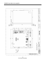
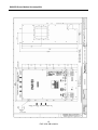
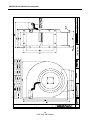
4. DIMENSIONS, ASSEMBLY, MASS,
LABELLING, CODING
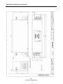
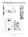
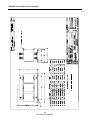
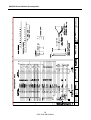
4.1 Dimensions, Assembly and Mass
See next pages, Drawing
FELX 306784
FELX 306125
FELX 306127
12
PVD 3522 GB 04/2004
DIGIVEX Power Motion Servoamplifier
13
PVD 3522 GB 04/2004
DIGIVEX Power Motion Servoamplifier
14
PVD 3522 GB 04/2004
DIGIVEX Power Motion Servoamplifier
15
PVD 3522 GB 04/2004
DIGIVEX Power Motion Servoamplifier
4.2 Labeling and coding
Markings :
•
On DPM 50/80 (DIGIVEX Power Motion 50/80) :
∗ one front panel label as shown on model below
This label gives the electrical characteristics required by UL and c UL drive compliance.
Meaning of label indications :
- AC SERVO :
- DPM 27050
- Serial Nr :
- Date :
- Input :
- Output :
- Voltage :
- Phase :
- Current :
- Freq.:
- Moteur :
- Classe :
- IP20 :
•
Alternating current converter
DPM50/80 servoamplifier code
Servoamplifier serial number
Manufacturing date
Input characteristics
Output characteristics
RMS Voltage
Phase number
RMS Current
Fréquency in Hz
Motor power in kW et in HP
Service class according to NF EN60146
standard, 1= permanent
Protection indice according to NF EN 60529
standard
On DPM (DIGIVEX Power Motion) :
∗ one front panel label as in the model below :
Meaning of label markings :
- CA/CA
converter alternating current / alternating current converter
- DPM----DIGIVEX Power Motion servoamplifier code
- E: 3 x 400V --A
Input voltage and current
- fn
Frequency
- S: 0-55V --Â
Output voltage and permanent output current (Amps. Peak)
- Classe
Service class to standard NF EN60146, 1 = permanent
- Serial number and date of manufacture
16
PVD 3522 GB 04/2004
DIGIVEX Power Motion Servoamplifier
•
On DPC (DIGIVEX Power Control) removable block (excluding DPM 50/80):
Drive customization parameters are recorded in a plug-in EEPROM. They can only be read via a
PC with PME DIGIVEX Motion software.
•
For DPM 50/80
The cover of the drive must be removed to access the EEPROM located on the SP6606 card
Codes
Power supply 400/480V
CODE
DPM27050DPM17100DPM17150DPM17200DPM17300-
FUNCTION
DPM 50/80
DPM 100/120
DPM 150
DPM 200
DPM 300
For DPM 200 and DPM 300 devices the sales reference for compulsory fan-cooling can be found
in 4.4.
DPMxxxxxC : DPM with fieldbus interface CANopen
DPMxxxxxP : DPM with fieldbus interface Profibus
17
PVD 3522 GB 04/2004
DIGIVEX Power Motion Servoamplifier
4.3 Front panel, terminal blocks and SUB-D plugs
4.3.1 Description of terminal blocks and sockets
All the input/outputs required for operation are arranged on the front panel in the form of :
-
B1 “MAIN SUPPLY”.
B2 “AUXILIARY SUPPLY”
B3 “BRAKE SUPPLY”.
B4 auxiliary power supply terminal block.
B5 terminal block for automatic control connection.
B6 “READY” (Drive ready for connection to mains), “OK” (regulation and power OK)
B7 “RESET”
Connectors with metal-plated or metallic covers.
ITEM REF.
X1
FIELDBUS
X2
INPUTS/
OUTPUTS
CONNECTOR TYPE
(cable end)
9-pin plug for
soldering
37-pin plug for
soldering
X3
ENCODER
9-pin plug if encoder
emulator output
9-pin socket for
soldering
X4
RESOLVER
9-pin socket for
soldering
FUNCTION
Fieldbus
connection
Logic and
analog
inputs / output
Encoder emulation
output (option)
Incremental
encoder input
(option)
Resolver link
MAX. CONDUCTOR
CROSS-SECTION
max. 0.5 mm² on
soldering barrel
max. 0.5 mm² on
soldering barrel
max. 0.5 mm² on
soldering barrel
max. 0.5 mm² on
soldering barrel
- For the DPM 50/80:
The motor earth must be connected to the ground terminal.
- For the DPM 100/120, DPM 150, DPM 200 and DPM 300:
The motor earth must be connected to the Faston earth lug on the appliance. The SUB-D plugs
used must be metal-coated (or metal) and provide continuous shielding through to the appliance's
metal earth.
The equipment
• Receives the 230 V or 400V/480V mains supply through terminal block B1 and
converts it into 550V dc voltage.
• Returns braking energy to the mains network (diode bridge + IGBT transistors).
• The single-phase 400V or 480V mains supply is fed into terminal block B2 to
generate the auxiliary supplies (± 15V,± 12V pour les DPM 50/80, 5V, 24V)
required for regulation.
• 24V supply for the motor brake may be fed into terminal block B3.
• Ensures interface with automatic control via terminal blocks B6 and B7.
18
PVD 3522 GB 04/2004
DIGIVEX Power Motion Servoamplifier
4.3.2 Description of 7-segment display and LEDs
•
•
•
•
•
•
A 7-segment "STATUS" display shows the drive operating status.
A green "POWER ON" LED indicates the auxiliary supply and power supply are on.
A "POWER OFF" red LED indicates there is no power supply.
An "OVERVOLT." red LED indicates excess mains or bus voltage.
A "PHASE" red LED indicates no mains phase (three-phase appliances only).
An "OVER CUR" red LED indicates either excessive internal current in the power supply or
a problem with the capacitor precharging circuit (load current limiting resistor cut out or
internal contactor damaged).
4.3.3 Rotary mini-switch setting (ADDRESS)
Each appliance in the same network CAN or Profibus must have a different subscriber number.
A rotating, 16-position, mini-switch is used to define the number of the appliance.
For information:
0
1
2
3
.
.
.
.
A
B
C
D
E
F
Prohibited
1*
2*
3
.
.
.
.
10
11
12
13
14
15
* The “1” and “2” addresses are prohibited to the Profibus bus
The subscriber code may be extended. Please ask for details.
Attention! For a subscriber number change to be acknowledged, the appliance must be
switched off completely for a few seconds.
19
PVD 3522 GB 04/2004
DIGIVEX Power Motion Servoamplifier
4.3.4 Diagrams
Front panel DPM 50/80
20
PVD 3522 GB 04/2004
DIGIVEX Power Motion Servoamplifier
Front panel DPM 100/120 and DPM 150
21
PVD 3522 GB 04/2004
DIGIVEX Power Motion Servoamplifier
Front panel DPM 200 and DPM 300
22
PVD 3522 GB 04/2004
DIGIVEX Power Motion Servoamplifier
Front panel Mobile block
For DPM 100/120, DPM 150, DPM 200 and DPM 300
23
PVD 3522 GB 04/2004
DIGIVEX Power Motion Servoamplifier
4.4 Accessories
4.4.1 Input mains filter
♦
♦
♦
♦
♦
For DPM 50/80: FR 03636
For DPM 100/120: FR 03064
For DPM 150: FR 03100
For DPM 200: FR 03200
For DPM 300: FR 03200
Dimensions as in drawing FELX 304967 and 305452 (see next pages).
4.4.2 Inductors for long cables
Inductances for long cables between motor and servoamplifier. Selection, see §5.8.6 Dimensions,
see drawing FELX 302983 (next pages).
•
Ventilation
CODE
FUNCTION
DPD/IS
DPM300/200 - Straight inlet
DPD/I90
DPM300/200 - Elbowed inlet
DPD/OS
DPM300/200 - Straight outlet
DPD/FOS
DPM300/200 - Straight fan outlet
DPD/FO90
DPM300/200 - Elbowed fan outlet
VN 10001
DPM300/200 - 400V 50Hz fan and 480V 60Hz fan
VN 02004
DPM300/200 - Hose
VN 02006
DPM300/200 - Protective mesh
24
PVD 3522 GB 04/2004
DIGIVEX Power Motion Servoamplifier
25
PVD 3522 GB 04/2004
DIGIVEX Power Motion Servoamplifier
26
PVD 3522 GB 04/2004
DIGIVEX Power Motion Servoamplifier
27
PVD 3522 GB 04/2004
DIGIVEX Power Motion Servoamplifier
28
PVD 3522 GB 04/2004
DIGIVEX Power Motion Servoamplifier
29
PVD 3522 GB 04/2004
DIGIVEX Power Motion Servoamplifier
30
PVD 3522 GB 04/2004
DIGIVEX Power Motion Servoamplifier
5. ELECTRICAL CONNECTIONS
5.1 General Wiring Requirements
5.1.1 Appliance handling
See the safety instructions given at the beginning of this manual. In particular, wait for all the front
panel LEDs to go off completely before doing any work on the servo-amplifier or servomotor.
5.1.2 Electromagnetic compatibility
EARTHING
•
Comply with all local safety regulations concerning earthing.
•
Utilize a metal surface as an earth reference plane (e.g. cabinet wall or assembly
grid). This conducting surface is termed the potential reference plate. All the
equipment of an electrical drive system is connected up to this potential reference
plate by a low impedance (or short distance) link. Ensure the connections provide
good electrical conduction by scraping off any surface paint and using fan
washers. The drive will then be earthed via a low impedance link between the
potential reference plate and the earth screw at the back of the DPM. If this link
exceeds 30 cm, a flat braid should be used instead of a conventional lead.
CONNECTIONS
• Do not run low-level cables (resolver, inputs/outputs, NC or PC links) alongside
what are termed power cables (power supply or motor). Do not run the power
supply cable and the motor cables alongside one another otherwise mains filter
attenuation will be lost. These cables should be spaced at least 10 cm apart and
should never cross, or only at right-angles.
•
Except for the resolver signals, all low-level signals will be shielded with the
shielding connected at both ends. At the DPM end, the shielding is made
continuous by the Sub-D connector mechanism.
•
The motor cables are limited to the minimum functional length. The yellow and
green motor cable lead must be connected to the box or front panel terminal block
with the shortest possible link.
•
This usually means shielded motor cable is not required. Chokes may also be
inserted into the motor phase leads.
31
PVD 3522 GB 04/2004
DIGIVEX Power Motion Servoamplifier
MAINS FILTERING
The equipment complies with standard EN55011 with a filter on the power input with minimum
60dB attenuation in the 150 kHz - 30 MHz range.
The network filter must be fitted to the ground reference plane (TRP) at the mains end, ahead of the
KM contactor and as close as possible to the DIGIVEX Power Motion.
A shielded power cable or a cable in a metal jacket must be used between the DIGIVEX Power
Motion and the KM contactor as well as between the KM contactor and the filter.
Avoid running cables together ahead of and after the filter.
Do not connect other appliances in parallel with the DIGIVEX after the KM.
The filtre+drive+motor unit sometimes has high leakage currents which can give rise to the
tripping of the ground fault circuit breaker. The ground fault circuit protection must have a
minimum threshold of 300mA. We recommend the use of delayed ground fault circuit breakers.
OTHER MEASURES
Self-inducting components must be protected against interference: brakes, contactor or relay
coils, fans, electro-magnets, etc.
5.1.3 DIGIVEX Power Motion Sub-D connectors
In order to ensure the system is free from disturbances, it is essential for the rack to be properly
connected to the earth plane of the electrical cabinet and for the covers of the Sub-D connectors
to be EMI/RFI shielded (metal with shielding braid connection).
Make sure the Sub-D connectors and their covers are properly connected (lock screws fully
tight).
GROUND CONNECTION
Fold the shielding braid over the
cable sheath
Solder between the braid and the
green and yellow lead.
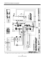
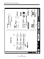
5.2 Typical Connection Diagram
See drawing FELX306785, FELX306126 and 306128.
It is mandatory to connect the auxiliary power supply to check the condition of the variable speed
control before power is applied.
The automatic control diagram must be complied with in full.
32
PVD 3522 GB 04/2004
DIGIVEX Power Motion Servoamplifier
33
PVD 3522 GB 04/2004
DIGIVEX Power Motion Servoamplifier
34
PVD 3522 GB 04/2004
DIGIVEX Power Motion Servoamplifier
35
PVD 3522 GB 04/2004
DIGIVEX Power Motion Servoamplifier
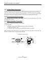
5.2.1 Surge Suppressor
- KM:
- AP:
Power Contactor
Surge Suppressor
The power contactor coil KM should necessary have a surge suppressor AP connected in order
not to destroy prematurely the internal relay contact of the drive. This module should be use
whether the power contactor supply is AC or DC.
The relay manufacturers (Telemecanique: LC1 series, ABB: B series,…) provide surge
suppressors fitted relays wether the power contactor supply is AC or DC for various voltages (RC
module, Diode+Zener Diode, Varistor,…).
36
PVD 3522 GB 04/2004
DIGIVEX Power Motion Servoamplifier
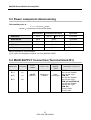
5.3 Power component dimensioning
The installed power is :
P ~= 1.1 U rms x I0 motor
where I0 = permanent current at low speed
Maximum I0
Recommended fuses
gG 32
AJT 40 (*)
Input filter
DPM 50/80
50 A
FR 03636
DPM 100/120
100 A
gG 63
FR 03064
DPM 150/150
150 A
gG 100
FR 03100
DPM 200
200 A
gG 125
FR 03200
DPM 300
300A
gG 200
FR 03200
May be replaced by circuit breakers.
(*): UL and c UL compliance required: UL fuse 40A/600V JDDZ
5.4 MAIN SUPPLY Connection (Terminal block B1)
MARKING TERMINAL
B1/1
U1
B1/2
V1
B1/3
W1
FRONT
PANEL
MAINS
SUPPLY
FUNCTION
Connection
To Mains
TERMINAL
BLOCK
TYPE
fixed,
screw-type
37
PVD 3522 GB 04/2004
TERMINAL CAPACITY
DPM 50
max 10 mm² flexible
max 16 mm² rigid
DPM 100
max 25 mm² flexible
max 35 mm² rigid
DPM 150 and DPM 200
max 50 mm² flexible
max 50 mm² rigid
DPM 300
35 mm² rigide
95 mm² maxi
DIGIVEX Power Motion Servoamplifier
5.5 Auxiliary supply Connection (Terminal block B2)
The supply required for regulations (±15V,±12V for DPM 50/80, 5V, 24V, fans (not for 200A and
300A) are taken internaly from the D.C direct voltage (rated 550V) which may be obtained :
•
•
either via a single-phase supply from the mains, between two phase wires ahead of
the main contactor (terminal block B2 input);
or from an independent single-phase supply (230V or 400V/480V), connected to
terminal block B2. In this case, the supply must be isolated from the mains by a
transformer (secondary 230V or 400V/480V ±10% 100VA for DPM 50/80 to DPM
150 and 200 VA for DPM 200 and DPM 300).
UL and c UL compliance required: AM2A or ATDR2A fuses (Class CC UL fuses) are necessary to
protect the auxiliary input.
MARKING
TERMINAL
FRONT
PANEL
FUNCTION
B2/1
B2/2
u1
v1
AUXILIARY
SUPPLY
Low
Level Supply
TERMINAL
BLOCK
TYPE
fixed,
screw-type
TERMINAL CAPACITY
min 0,2 mm²
max 4 mm² flexible wire
max 6 mm² rigid wire
5.6 Brake Supply Connection (Terminal block B3)
A 24V supply may be fed into this terminal block for the brake fitted to the motor. It is fed to the
motor terminal block B4.
Regulated/filtered 24V ±10%. Protection against overvoltage by 26 Joule varistor. This protection
is operational from 30V.
UL and c UL compliance required: 2A fuse (UL recommended) on the +24VDC voltage.
WARNING: Do not use the 24V on terminal block B7 for this function.
MARKING
B3/1
B3/2
TERMINAL FRONT PANEL
+24V
0V
BRAKE
SUPPLY
FUNCTION
24V
input for brake
TERMINAL
BLOCK TYPE
unpluggable,
screw-type
38
PVD 3522 GB 04/2004
TERMINAL CAPACITY
min 0,2 mm²
max 2,5 mm² flexible wire and
rigid
DIGIVEX Power Motion Servoamplifier
5.7 Earth connection
Chassis earth:
To comply with UL 508 C, the earth wire cross-section should be at least 10AWG (6mm²)
To comply with existing standards, the copper earth wire cross-section should be identical to that
of the mains connection up to 16 mm².
For "mains" cross-sections between 16 mm² and 35 mm², the minimum cross-section for the
ground conductor is 16 mm².
For "mains" cross-sections greater than 35 mm², the cross-section of the ground conductor should
be at least equivalent to half the cross-section of the mains conductor.
5.8 Short-circuit capability
UL and c UL compliance required: the DPM50/80 should be used with power circuits with a
maximum capability of current equal to 5000Arms symmetrical (UL 508 C)
5.9 Motor end connection
5.9.1 Terminal block B4 and B5
MARKING TERMINAL
FRONT
PANEL
B4/1
B4/2
TH
TH
TH
B4/3
B4/4
B5/1
B5/2
B5/3
+
U1
V2
W2
BR
MOTOR
FUNCTION
Motor thermal
protector
Motor brake
control
Connection
to
Motor
TERMINAL
BLOCK
TYPE
TERMINAL CAPACITY
min 0,2 mm²
unpluggable, max 2,5 mm² flexible wire
screw-type and rigid
Fixed
screw-type
39
PVD 3522 GB 04/2004
DPM 50/80
max 10 mm² flexible
max 16 mm² rigid
DPM100A
max 25 mm² flexible
max 35 mm² rigid
DPM 150 and DPM 200
max 50 mm² flexible
max 50 mm² rigid
DPM 300
35 mm² rigide
95 mm² maxi
DIGIVEX Power Motion Servoamplifier
5.9.2 Motor Power connection
UL and c UL compliance required: Only use cables with copper core
There are two possibilities for connection:
Terminal block + resolver connector.
Power connector + resolver connector.
5.9.3 Terminal block connection
For the terminal block, the clamping nuts and washer come in a bag
Take care when fitting the lugs not to loosen the connecting leads between the motor and the
terminal block.
The power connection lugs are to be inserted between
the striated washer and the flat washer.
Motor direction of rotation: by wiring as recommended, a positive set point applied to the drive
entails clockwise rotation (viewed from the power shaft end).
ALIMENTATION/SUPPLY/SPEISUNG
U Phase U
V Phase V
V
U
1
2
W
3
4
W Phase W
1 Optional brake +24 V
2 Optional brake
FREIN/BRAKE
BREMSE
Thermal
sensor
3 Thermal sensor
4 Thermal sensor
40
PVD 3522 GB 04/2004
cable ≥ 1mm²
0V
cable ≥ 1mm²
DIGIVEX Power Motion Servoamplifier
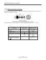
5.9.4 Power connector connection
Power can be connected using a connector as an option. The removable part of the connector
(plug) can be supplied on request.
PLUG 220065R3610
PERMISSIBLE CABLE CROSS-SECTION FOR PLUGS
PLUG 220065R3610: Power & Ground: 6 - 16 mm². Brake & thermal protection: 1 - 2.5 mm².
PIN OUT
220065R3610
+
1
2
FUNCTION
BRAKE +
BRAKE THERMAL PROT.
THERMAL PROT.
GROUND
U2
V2
W2
U
V
W
Shielding to be connected to
the earth at the servoamplifier
end
41
PVD 3522 GB 04/2004
CABLE COLOUR
Green/Red
Green/Blue
Orange
Yellow
Green/Yellow Black
White
Red
Green/Orange
DIGIVEX Power Motion Servoamplifier
5.9.5 "POWER" Cable Definition
The power/drive connector cables must have as a minimum requirement :
•
Three insulated conductors connected to U2, V2, W2 phases. Cross-sections as in the
table below. The internal chokes of the DIGIVEX Power Motion allow, as a general rule,
there is no need to use shielding on the three power conductors.
one ground conductor (green/yellow).
one shielded twisted pair for connection of the motor thermal protection. Cross-section
of about 1 mm².
one shielded twisted pair for connection of the holding brake (if fitted). Cross-section of
about 1 mm².
1 " shielding continuity " conductor (green/orange) to be connected to the servoamplifier
earth
•
•
•
•
Power cable cross-section
Cable cross-sections shown in the table below make allowance for :
•
•
•
•
rated drive current;
motor/drive distance, service voltage loss = RI.
ambient temperature, cable Joule losses = RI².
standardised increase of cable cross-sections.
Depending on distance, following cable cross-section should be used (ambiant < 40°C).
Distance Î 0m
DIGIVEX Rating
DPM 50/80
DPM 100/120
DPM 150
DPM 200
DPM 300
*
**
***
100m
200m
Cable cross-section in mm²
10
16/25*
25
25/50**
50
50/70**
50 ***
95 ***
In the case of a 230V three-phase power supply, cross-section not compatible with the power
terminal blocks, provide an intermediate terminal block.
In the case of a 230V three-phase power supply.
For an ambient temperature of 30°C
42
PVD 3522 GB 04/2004
DIGIVEX Power Motion Servoamplifier
Power cable list, power plugs and equiped cables for H series motors.
Cable crosssection
(mm²)
MOTOR
NX860
HD-HX-HV800
HS900
HD-HV900
HXA-HVA
every HW
HD-HV1000
Power
Cables
Power
Plugs (1)
Equiped
cables
6
6537P0012
6537P0011
-
-
10
6537P0012
220065R3610
220049R46..
16
6537P0013
220065R3610
220049R47..
25
6537P0014
Length 05m/10m/15m/25m/50m. Add the cable length to the equiped cable reference.
(1) Option for H motors
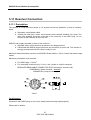
5.9.6 Guidelines for long cables between the motor and drive
For the DPM 50/80, DPM 100/120 and DPM 150, provide inductors for lengths of more than 70m
(standard cable) or 50 m (shielded cable) as shown in the table below. These inductors cannot be
used with flux weakening motors (spindle motors). The cable length must be less than 70m
(standard cable) or 50 m (shielded cable) for these motors.
To be fitted between the DIGIVEX Power Motion (as close as possible to the drive) and the motor.
Dimensions
U2
Servoamplifier V2
W2
CHOKE
Motor
CHOKE
CHOKE
DPM 50/80
DPM 100/120
DPM 150
Standard
70 to 200 m
100 to 200 m
Shielded
50 to 135 m
70 to 135 m
Length cable
Choke
SF02026
340 µH
43
PVD 3522 GB 04/2004
SF02026
340 µH
SF02027
190 µH
DIGIVEX Power Motion Servoamplifier
5.9.7 Holding Brake Connection
Brushless motors may be fitted with a brake of suitable dimensions to hold the motor immobilised. If 24
V dc ±10% is applied across the brake terminals, the brake disc is released and the motor can rotate.
The 24 V dc current for brake control must be regulated/filtered. It is to be connected to terminal block
B3 and is then distributed internally. The brake is to be connected to terminals B4/3 and B4/4.
5.9.8 Thermal protection Connection
The 2 terminals of the PTC sensor or dry contact, located in the motor terminal box, are to be
connected to B4/1 and B4/2.
5.9.9 Motor Ventilation Connection
Some motors can be delivered as fan-cooled versions.
Fan characteristics :
• Supply voltage : 400V or 480V three-phase, 50/60 Hz as standard.
• Power consumption : 45 W
• Connector type connection (plug 220056P0200 supplied on request).
When connecting check the direction of fan rotation and check that airflow is produced. The
direction of airflow is shown on the dimension drawings.
Removable connector plug
View F
44
PVD 3522 GB 04/2004
DIGIVEX Power Motion Servoamplifier
5.10 Automatic control Input / Output connection
5.10.1 Terminal block B6 and B7
MARKING
TERMINAL
B6/1
B6/2
1
2
FRONT
PANEL
READY
OK
3
4
B6/3
B6/4
B7/1
B7/2
+24V
0V
B7/3
B7/4
B7/5
B7/6
B7/7
+15V*
0V
-15V*
+
-
FUNCTION
TERMINAL
BLOCK TYPE
TERMINAL CAPACITY
Drive ready for
connection to mains
regulation and
power OK
24V
output
« user »
unpluggable,
screw-type
min 0,2 mm²
max 2,5 mm² flexible wire
and rigid
unpluggable,
screw-type
min 2 mm²
max 2,5 mm² flexible wire and
rigid
+/-15V* « user »
output
RESET
logic input
*+/-12V for DPM 50/80
- B7/1
- B7/2
24 V regulated
0 V of 24 V
•
•
Max. 24 V - 50 mA power supply. Do not use for brake supply.
Protection against overloads and short circuits by current limitation.
This supply is for logic inputs but is also used internally for the fan power supply. There is no
common point with the metal case.
- B7/3
- B7/4
- B7/5
+15V regulated (+12V regulated for DPM 50/80)
0V of 15V (0V of 12V regulated for DPM 50/80)
-15V regulated (-12V regulated for DPM 50/80)
•
•
Maximum power supply +/-15V - 10mA (maximum of +/-12V - 100mA for DPM 50/80)
Protected by 47 ohms resistor (DPM 50/80 protected by regulator)
This supply is common with the internal supply of the POWER SUPPLY module. There is no
common point with the metal casing.
- B7/6 Reset +
- B7/7 Reset-
(24V DC logic input)
(0V)
A 24 V rising edge applied across B7/6 compared with B7/7 resets the system after a power
supply or drive fault.
Note that the front panel reset button can also be used, or turning off the power completely (power
and auxiliaries).
This control has no effect during normal operation.
The system must be "reset" after any active fault.
See the PME-DIGIVEX Motion setting and adjustment manual for further details.
45
PVD 3522 GB 04/2004
DIGIVEX Power Motion Servoamplifier
5.10.2 main contactor control
- B6/1 - B6/2 : READY contact
Cut-out power : max voltage 250 Vac, max 1A.
This contact is closed if :
• the D.C voltage is correct (>200V dc),
• the drive has not indicated any "regulation" type fault (no resolver, incorrect low level
auxiliary supply, fault not erased by "reset").
This contact allows test closure of the main contactor. The "POWER OFF" LED lights.
It is mandatory to wire the ready contact into the power supply automatic control line of the main
contactor.
- B6/3 - B6/4 : OK Contact
Cut-out power : max voltage 250 Vac, max 1A.
The contact is closed if :
•
•
power supply is present (>200 V dc)
the servoamplifier, auxiliary and power, indicates no faults
The contact allows the main contactor to be self-maintained
•
the green POWER ON LED lights.
Main contactor management
Closure of the "READY" relay (if the external safety devices are correct) authorises closure of the
main contactor, if the ON push button is activated. The OK relay button ensures the main
contactor self-holds for 30 ms after the ON command.
Conversely, opening of the "OK" relay causes the main contactor to open. The "OK" relay opens
in the following circumstances :
•
•
•
•
•
•
•
•
No phase
Recovery fault
Maximum power bus voltage
Minimum power bus voltage
Drive fault
Auxiliary supply fault
Overcurrent
Current capacitors charging circuit damaged (current limiting resistor open or internal
contactor damaged).
46
PVD 3522 GB 04/2004
DIGIVEX Power Motion Servoamplifier
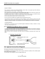
5.11 Resolver Connection
5.11.1 Description
The resolver is a high precision sensor (± 10 angular minutes as standard). It must be carefully
wired :
• Separately routed power cable.
• Twisted pair cable (sine, cosine, and excitation) with individual shielding of the pairs. The
three pairs shielding should be connected to the metal cap of the SUB-D plug. Do not
connect the pair shielding at the motor end
PARVEX can supply the cable in either of two versions :
• Separate cable, in this case wire as shown in the diagram below.
• Cable fitted with SUB-D plug at drive end and connector at motor end. This solution is
strongly recommended as the cable is ready for use.
Maximum distance between resolver and DIGIVEX Power Motion : 200 m. Please ask about longer
cables.
Maximum permissible cross-sections :
•
•
For SUB-D plug : 0.5 mm2.
For removable connector plug. 0.14 to 1 mm² (solder or crimp-fit contacts)
RESOLVER REMOVABLE CONNECTOR PLUG (connection at motor end)
220065R4621 (solder contacts - standard)
220065R1621 (crimp-fit contact)
View F
For XD motors
Connection with SUB-D plug on rear cover (cable inserted through special gland).
Please ask for details.
47
PVD 3522 GB 04/2004
DIGIVEX Power Motion Servoamplifier
5.11.2 Sub-D connector X4:"Resolver"
DIGIVEX end connections, Sub-D 9 pin connector item ref. X4 "RESOLVER".
Maximum conductor cross-section: 0.5 mm²
CONTACT
TYPE
FUNCTION
1
Input
Cosine S1
2
Input
Sine S2
3
Input
Cosine S3
4
Input
Sine S4
5
Output
6
-
7
-
8
-
9
Output
Excitation R1
Unused
Unused
Unused
0V Excite R2/3
5.11.3 Cables
Cables by meter:
product number : 6537P0001
Complete cables (fitted with plug at the motor end and SUB-D connectors at the DPM end):
product
number
220049R61xx
(xx :
length
in
metres
5m/10m/15m/25m/50m).
48
PVD 3522 GB 04/2004
DIGIVEX Power Motion Servoamplifier
49
PVD 3522 GB 04/2004
DIGIVEX Power Motion Servoamplifier
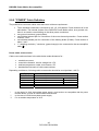
5.12 FIELDBUS Connections
5.12.1 SUB-D X1 plug : FIELDBUS
Identify the nameplate on the front end :
Æ
FIELDBUS = CANopen
Æ
FIELDBUS = Profibus
5.12.2 CANopen connections and cables
See DIGIVEX Motion - CANopen manual : PVD 3518
5.12.3 Profibus connections and cables
See DIGIVEX Motion - Profibus manual : PVD 3554
50
PVD 3522 GB 04/2004
DIGIVEX Power Motion Servoamplifier
5.13 Input/Output connection
5.13.1 SUB-D X2 socket: Inputs/Outputs
CONTACT
1
2
20
3
21
TYPE
0V
-12 V
+12 V
outa
0V
FUNCTION
Symmetrical supply available for
analogue I/O
CHARACTERISTICS
Max. current available = ±50 mA
±10V analogue output
4
22
28
10
9
27
8
26
7
25
6
24
5
23
37
18
36
17
35
16
34
15
19
33
14
32
13
31
12
30
11
29
ina +
ina + 24V
0V (1)
out 0
out 1
out 2
out 3
0V (1)
out 4
out 5
out 6
out 7
0V (1)
in0
in1
in2
in3
in4
in5
in6
in7
COM0
in8
in9
in10
in11
in12
in13
in14
in15
COM1
±10 V analogue input
Analogue conversion: ≈ 9 bits + sign
Output ±10V / 3 mA
Protected against short circuits
Analogue conversion: 13 bits + sign
Differential input
max. 400 mA for 8 outputs
Internally connected to X2-7 and X2-23
24 V PNP, optocoupled, max.
50 mA outputs,
protected against short circuits
+24 V input for logic output supply
0V logic outputs
Logic outputs
Logic outputs
Logic outputs
Logic outputs
0V logic outputs
Logic outputs
Logic outputs
Logic outputs
Logic outputs
0V logic outputs
Logic input
Logic input
Logic input
Logic input
Logic input
Logic input
Logic input
Logic input
Common for inputs in0-in7
Logic input
Logic input
Logic input
Logic input
Logic input
Logic input
Logic input
Logic input
Common for inputs in8-in15
51
PVD 3522 GB 04/2004
Internally connected to X2-10 and X2-23
24 V PNP, optocoupled, max.
50 mA outputs,
protected against short circuits
Internally connected to X2-7 and X2-10
Optocoupled logic inputs,
type 1 under IEC 1131-2
Optocoupled logic inputs,
type 1 under IEC 1131-2
DIGIVEX Power Motion Servoamplifier
5.13.2 Input/Output characteristics
5.13.2.1 Logic outputs (out0 - out7)
• opto-mos outputs (2.5 kV isolation voltage), 24 V dc / 50 mA,
• PNP-type static outputs (load connected to negative supply pole) with diode in parallel on load
and protection by current limitation,
• an output is said to be at 1 if it is activated (24 V dc output),
• user must provide 24 V dc supply for outputs (18 V ac rectified, filtered),
• 24 V dc supply input protected against reversals of polarity (diode).
To avoid any ill-timed output status change during drive initialization (when the auxiliary power
supply appears), it is recommended to wait about 3 seconds before switching on the 24V DC
supply of the outputs.
MIN
5V
0.05 mA
-
Supply voltage
Output current (level 1)
Residual current (level 0)
Response time Ton (0-1)
Response time Toff (1-0)
Output voltage drop I = 50 mA
TYPICAL
24 V
0.3 ms
0.2 ms
-
MAX
40 V
50 mA
0.001 mA
1 ms
1 ms
2V
5.13.2.2 Analogue output (outa)
Analogue output
Resolution
Maximum output current
Source impedance
:
:
:
:
+/-10V
≈ 10 bits (9 bits + 1 sign bit)
5 mA (minimum load 2 K)
100 ohms
3.3nF
ANALOGUE OUTPUT
40kΩ
47.5Ω
47.5Ω
2.2nF
52
PVD 3522 GB 04/2004
outA
0V
DIGIVEX Power Motion Servoamplifier
5.13.2.3 Logic inputs (in0 - in 15)
•
•
•
•
•
•
opto-coupled 24V dc inputs (5 kV isolation voltage),
type 1 inputs under IEC 1131-2,
input load resistance: 10 K,
an input is said to be at 1 if it is activated (24 V dc output). Otherwise it is said to be at 0,
inputs may be connected directly to PNP type outputs (no external load resistor required),
possibility of connecting 24 V dc "NC (normally closed) or NO (normally open) inductive
proximity detectors : 3-lead, PNP output type (load connected to negative supply pole.
Input voltage (level 0)
Input voltage (level 1)
Input current (level 0)
Input current (level 1)
Response time Ton (0-1)
Inputs In0-In3
Other inputs (in4-in15)
Response time Toff (1-0)
Inputs In0-In3
Other inputs (in4-in15)
MIN
15 V
3 mA
TYPICAL
0V
24 V
0 mA
7 mA
MAX
5V
30 V
0.5 mA
10 mA
-
0.2 ms
1 ms
-
-
0.2 ms
1 ms
-
+24V
+24V
+
1,21kΩ
10V
in
3-lead
detector
10 kΩ
Contact
0V
COM
1,21kΩ
53
PVD 3522 GB 04/2004
TLP121
DIGIVEX Power Motion Servoamplifier
5.13.2.4 Analogue input (ina)
•
•
•
•
•
Differential input
Resolution
Input impedance
Maximum consumption on +12 V
Maximum consumption on -12 V
:
:
:
:
:
+/-10V
14 bits (13 bits + 1 sign bit)
>40kΩ
10 mA max.
10 mA max.
ANALOGUE INPUT
13 BITS + SIGN
4.7nF
4.7nF
inaina+
22kΩ
11kΩ
22kΩ
-
22kΩ
22kΩ
+
11kΩ
4.7nF
4.7nF
5.13.3 Cable
Bare cables:
product number : CB 08304
Complete cables
product number : CYB04559R1 xx (xx : defines the length in m) (equipped
with SUB-D connectors). See drawing FELX 305974.
Product number of cable supplied by meter by Parvex: product number CB08307
54
PVD 3522 GB 04/2004
DIGIVEX Power Motion Servoamplifier
55
PVD 3522 GB 04/2004
DIGIVEX Power Motion Servoamplifier
5.14 Encoder emulation option connection (SC6639)
5.14.1 Description
This optional board, fitted in the DPM, converts the signal from the resolver into a series of
pulses identical to those from an incremental encoder: A, B, Zero Mark and their complements.
5.14.2 Sub-D connector X3: encoder emulation option
Sub-D 9-pin plug, "Encoder". Maximum conductor cross-section: 0.5 mm².
CONTACT
TYPE
FUNCTION
Characteristics
5
Input
5V
Max. current = 100 mA
9
Input
0V
7
Output
A
Encoder channel A
3
Output
A
Encoder channel A
8
Output
B
Encoder channel B
4
Output
B
Encoder channel B
6
Output
zero mark
Encoder channel zero mark
2
Output
zero mark
Encoder channel zero mark
56
PVD 3522 GB 04/2004
DIGIVEX Power Motion Servoamplifier
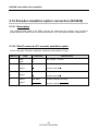
5.14.3 Programming resolution and zero mark position
This is done with the PME DIGIVEX-Motion. (See the Manual
PVD3516)
These parameters can be called up by selecting the "Input/Output parameters menu with the
"options" tab.
Resolution
Adjustable between 1 and 16384, either by +/- keys, or be entering the number directly (in "OFF
LINE" mode only).
Zero Mark Setting
Adjust by trial-and-error with the PC working in "ON LINE" mode.
When the operator judges the position is suitable, he confirms by acknowledging the zero mark.
5.14.4 Electrical characteristics
The electrical output interface meets standard RS422 for differential serial links. The circuit used
is a "LINE DRIVER" of the 26C31 type. The electrical characteristics are therefore closely related
to the use of this component.
Voltage supply
The encoder emulation boards are electrically isolated between the output stage through three
optocouplers, needing to be powered by an external +5V ±10%, 100 mA source, as for all
incremental encoders.
In no case can this power supply, which is intended only for electrical isolation, be used to keep
position information from the resolver in the event of failure of the drive's low-level power supply.
Short-circuit capability
A single output may be short-circuited at 0 V at any given time
57
PVD 3522 GB 04/2004
DIGIVEX Power Motion Servoamplifier
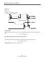
Signal form
Signal levels:
•
•
U high ≥ 2.5V for I high ≥ -20mA
U low ≤ 0.5V for I low ≤ 20mA
Switching time:
Rise or fall time defined from 10% to 90% of the magnitude in question, without cable and without
load.
tr = tf = 45ns (typical value)
Time delay between direct and complemented channels
Time delay defined at 50% of magnitudes in question without cable and without load.
-6ns ≤ ta ≤ 6ns (maximum)
maximum frequency : 500 kHz on signals A or B
58
PVD 3522 GB 04/2004
DIGIVEX Power Motion Servoamplifier
Time interval between channels A, B and the zero mark
Time delay defined at 50% of magnitudes in question without cable and without load.
-6ns ≤ td ≤ 6ns (maximum)
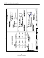
5.14.5 Cable
Cable can be supplied with SUB-D connectors, see drawing FELX 304554.
Product number
DIG 04546R1xx (2 SUB-D connector)
DIG 04546R2xx (1 SUB-D connector)
(xx : defines length in meters)
59
PVD 3522 GB 04/2004
DIGIVEX Power Motion Servoamplifier
60
PVD 3522 GB 04/2004
DIGIVEX Power Motion Servoamplifier
5.15 External
(SC6638)
encoder
input
option
connection
5.15.1 Description
This option board, placed in the DPM, is used to connect an external incremental encoder which
may be used:
• either as a master axis for synchronization with an external moving component, or as a cam
type function
• or as a position measuring device if position measurement given by the resolver is unsuitable,
Caution: in this case, the resolver must be connected nevertheless.
• or as a position measuring device for refined applications where allowance must be made for
position on the part and not on the motor,
Caution: in this case, the resolver must be connected nevertheless.
• or as an automatic control and a position measuring device
Caution: in this case, the motor shaft must be mechanically free so that the motor can be
polarized using user program as Motor_polarization.bdm which is to be found under :
C:\Program Files\Parvex\Pme4.xx\App_Parvex\Samples\Misc.
The drive in7 input and out7 output are assigned to this program :
•
in7 = 1
authorizes the polarization phase to start.
•
out7= 1
when the polarization phase is completed.
This program is only given as an example and can be modified according to the customer
application.
The position sensor must be an incremental encoder type, with complemented track, with a line
driver:
• tracks A, A , B, B , zero mark, zero mark
• supply +5 V
• maximum consumption 250 mA
• maximum frequency: 250 kHz on signals A or B
• Encoder +5V supply voltage is provided by the DPM from a +24V DC external supply.
61
PVD 3522 GB 04/2004
DIGIVEX Power Motion Servoamplifier
5.15.2 SUB-D X3 sockets: encoder input option
CONTACT
TYPE
Output
5
FUNCTION
Characteristics
max. 250 mA encoder supply Output
5V
: + 24 V supply to sockets X2-28 / X2-10 is
required for encoder supply
9
Output
0V
7
Input
A
Encoder channel A
3
Input
A
Encoder channel A
8
Input
B
Encoder channel B
4
Input
B
Encoder channel B
6
Input
Zero mark
Encoder channel zero mark
2
Input
zero mark
Encoder channel zero mark
5.15.3 Cable
The DPM-Encoder connection cable shall be made up of three twisted pairs of cross-section of
14 mm2 or more (for signal transmission) and one larger pair (for encoder supply).
Encoder supply cable cross-section:
•
•
•
•
•
•
•
•
20 m cable 150 mA current
35 m cable 150 mA current
10 m cable 200 mA current
20 m cable 200 mA current
50 m cable 200 mA current
10 m cable 250 mA current
20 m cable 250 mA current
40 m cable 250 mA current
0.5 mm²
1 mm²
0.5 mm²
1 mm²
2.5 mm²
0.75 mm²
1.5 mm²
2.5 mm²
Æ
Æ
Æ
Æ
Æ
Æ
Æ
Æ
Some of the cross-sections defined above are difficult to wire to a SUB-D connector, in which case
the following wiring arrangement may be used.
Signal A
A
B
B
zero mark
zero mark
encoder
Sub D
encoder
connection
Small cross-section cable as
shortest possible
Large cross-section shielded 0V/+5V
For higher values an external +5V supply must be installed near to the encoder to prevent voltage
loss over long lengths of cable.
62
PVD 3522 GB 04/2004
DIGIVEX Power Motion Servoamplifier
Input interface :
Input voltage MIN.
MIN
TYPYCAL
MAX
level 0
-
0V
1V
level 1
3V
5V
5.5 V
100Ω
1 nF
220Ω
100Ω
63
PVD 3522 GB 04/2004
DIGIVEX Power Motion Servoamplifier
64
PVD 3522 GB 04/2004
DIGIVEX Power Motion Servoamplifier
65
PVD 3522 GB 04/2004
DIGIVEX Power Motion Servoamplifier
5.16 Connecting the SinCos encoder input option
(SC6645)
5.16.1 Description
This optional card, placed in the DPM, is used to connect a SinCos encoder which acts as an
automatic motor and position measurement control unit for applications requiring both rotation
speed and significant resolution.
Attention: in this case, the motor shaft must be mechanically free so that the motor can be
polarized using a user program w as Motor_polarization.bdm which is to be found under
C:\Program Files\Parvex\Pme4.xx\App_Parvex\Samples\Misc\.
The input (in7) and the output (out7) are assigned to this program:
• in7 = 1 authorizes the polarization phase to start.
• out7= 1 when the motor polarization phase is completed.
This program is only given as an example and can be modified according to the customer
application.
In addition, a program available under PME (Parameter editor -> Motor/Resolver -> Setting
SinCos encoder parameters) can be used to equalize any SINE and COSINE channel offsets as
well as any differences in amplitude between the same channels.
The resolution obtained via the SinCos encoder is given by the formula:
RESOLUTION = NUMBER OF ENCODER PERIODS OF SINE X INTERPOLATION FACTOR
with the INTERPOLATION FACTOR being approx. equal to 512 points; the interpolation factor is
the breakdown of a sinusoidal signal as a given number of points.
The position sensor should be a SinCos encoder with sinusoidal outputs:
• Tracks A, A , B, B , Top0, Top0 (analog).
• 2 signals, A and B, in quadrature and their inverted signals A B , being short circuit resistant.
• Maximum number of authorized encoder periods of sine: 65536 periods/revolution.
• Level of differential peak to peak voltages A A and B B between 0.8 V (AC) and 1.1 V (AC).
•
Power supply +5V.
•
Maximum consumption 250 mA.
•
Maximum frequency: 200 kHz for the A or B signals.
• An external 24V +/- 10% power supply must be provided to supply the SC6645 option card via
the DSM SUB-D X2 (Contact 28: + 24V, Contact 10: 0V). An isolated DC-DC converter
(24V /5V), on the option card is used to supply the encoder with 5V.
Attention: The external power supply needs to be 24V DC +/- 10%.
66
PVD 3522 GB 04/2004
DIGIVEX Power Motion Servoamplifier
5.16.2 SUB-D X3 plug: Encoder input option.
CONTACT
5
TYPE
Output
ROLE
5V
9
Output
0V
7
Input
A
Characteristics
Encoder power supply: maximum output 250 mA.
: a +24V power supply for X2-28 / X2-10 plug is
required for processing the encoder power supply
Encoder channel A
SINE signal (differential inputs)
3
Input
A
Encoder channel A
8
Input
B
Encoder channel B
COSINE signal (differential inputs)
4
Input
B
Encoder channel B
6
Input
Top 0
Encoder channel Top 0
(differential inputs)
2
Input
Top 0
Encoder channel Top 0
5.16.3 Cables
The DPM connection cable should be made up of 4 twisted pairs, shielded in pairs, with sections
greater than or equal to 0.25 mm2.
The maximum cable length is 40 m. Please consult us for information on longer cable lengths.
There is an approved PARVEX cable for controlling with SinCos encoder.
Input interface:
The input signals for the encoder input card should be sinusoidal and differential with peak to
peak values between 0.8 V and 1.1 V.
67
PVD 3522 GB 04/2004
DIGIVEX Power Motion Servoamplifier
68
PVD 3522 GB 04/2004
DIGIVEX Power Motion Servoamplifier
6. COMMISSIONING - DIAGNOSTICS
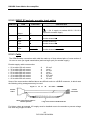
6.1 Start Up Sequence
6.1.1 Prior Checks
Wiring Check
• Power and auxiliary connections to DIGIVEX Power Motion.
• Wiring of Reset.
• External arrival of 24 V source for motor brake.
• Check resolver connections :
♦ at motor end
♦ at DIGIVEX Power Motion.
• Check the power, brake and thermal sensor connections :
♦ at motor end
♦ at DIGIVEX Power Motion.
Power Supply Type Check
• Power : 50/60 Hz, 400V +/- 10% or 480 + 10%.
• Auxiliaries : single-phase, 50/60 Hz, 400 V ± 10% or 480V + 10%.
• Brake supply : 24 V dc ± 10% (ripple included).
Warning: Before any work make sure that the power bus is at 0 V. Wait at least three minutes
after the motors have come to a complete stop before carrying out any work. Wait for all LEDs to
go out.
6.1.2 Commissioning with PME-DIGIVEX Motion
See the Manual
PVD3516
69
PVD 3522 GB 04/2004
DIGIVEX Power Motion Servoamplifier
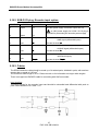
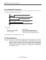
6.2 Initialization Sequence
Description of initialization sequence times:
Tok
t
Tcapa
t
Tinit
t
To
Upon energizing:
To
To+30ms < Tok < To+120ms
To+300ms <Tcapa<To+700ms
Tinit > Tcapa+60ms
<= Mains present
=> "OK" relay closed (terminal block B6)
=> capacitor preload internal contactor closed
=> INIT signal. (LED POWER ON lights up)
The "drive OK" output on plug X2 is set to 24V
The INIT (initialization) signal enables the drive to work.
6.3 Stop Sequence
Attention: In the case of a motor with flux weakening (HV or HW spindle motor), the mains
contactor should not be opened when the motor speed is greater than 50 rpm.
Opening the contactor may cause overvoltages on the DC power bus and shorten
the life of the drive. For emergency stops, we recommend that an electric braking be
induced through an action on move_en or emergency_cmd. A waiting period
corresponding to the maximum braking time of the motor should be observed before
the contactor is opened.
70
PVD 3522 GB 04/2004
DIGIVEX Power Motion Servoamplifier
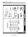
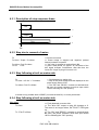
6.3.1 Description of stop sequence times
Tok
t
Tcapa
t
Tinit
t
To
6.3.2 Stop due to removal of mains
To
To+3ms < Tcapa < To+60ms
<= Removal of mains.
=> Power bridge is stopped and capacitor preload
internal contactor is opened.
=> "OK" relay is opened on terminal block B6.
=> After a time period Td, approx. 2s, the status of the
INIT signal changes. Furthermore, after this time, the
"drive OK" output on plug X2 is set to 24V.
To+25ms <Tok<To+60ms
To+Td < Tinit
6.3.3 Stop following a fault on mains side
To
To+3ms < Aff. Def. < To+200ms
To+25ms <Tok<To+200ms
⇐ Fault detected on mains side
⇒ Stop of the power bridge and fault displayed on the
power supply status LEDs.
⇒ The "OK" and "READY" contacts on terminal block
B6 open, the power contactor must then open within
100 ms following the "OK" opening.
A restart is only possible after a RESET (on terminal block B7) or via the push button.
6.3.4 Stop following a fault on motor side
Axis motor:
To
To+3ms:
To <Tok<To+20ms
<= Fault detected on motor side.
=> The "drive OK" output on plug X2 changes to 0.
The motor is no longer driven, the "FAULT" LED lights
up.
=> The "OK" and "READY" contacts on terminal block
B6 open, the power contactor must then open within
100 ms following the "OK" opening.
71
PVD 3522 GB 04/2004
DIGIVEX Power Motion Servoamplifier
Spindle motor:
To
<= Fault detected on motor side.
To+3ms+Tf:
=> The fault is passed on to the power supply when
the motor speed is less than 50 rpm after a time
period Tf (Braking time), the "OK" and "ready"
contacts then open.
A restart is only possible after a RESET (on terminal block B7) or via the push button. The RESET
is not active until the cause of the fault has been removed.
6.4 Detecting Reasons for Stoppage
6.4.1 LED display - power supply function
LED
POWER ON
POWER OFF
COLOR
Green
Red
OVER CUR
Red
OVER VOLT
PHASE
Red
Red
FUNCTION
Power on, with no fault in the supply or in the drive control.
Auxiliary supply on. No power supply (either because of a
fault, or by switching off).
Internal excess current of supply, or current capacitors
charging circuit damaged (current limiting resistor open or
internal contactor damaged).
Bus and mains overvoltage values are as follows:
No mains power phase.
Lit continuously: Mains overvoltage or Bus overvoltage
Bus overvoltage
850V
Mains overvoltage
550Vrms
In normal operation, the LED status is as follows :
• POWER ON
Green
• POWER OFF
Off
• OVER VOLT
Off
• OVER CUR
Off
• PHASE
Off
Power supply current monitoring:
DPM
50/80
DPM
100/120
DPM
150
DPM
200
DPM
300
Max bus operating current for 100 ms
50
100
150
200
300
Mains bridge blocking instantaneous current
90
150
210
300
450
72
PVD 3522 GB 04/2004
DIGIVEX Power Motion Servoamplifier
6.4.2 Current Monitoring
Drive mean current
Each servoamplifier is characterized by two currents.
For example for a DIGIVEX Power Motion 50/80 :
♦ permissible permanent current 50A (sine wave peak value),
♦ maximum pulse current 80A, permissible for a limited time (0.3 - 1 s).
To prevent excessive overheating of the drive the mean current [I = f(t)] is compared after
about two seconds filtering with the permanent permissible current (rating).
There is then a choice between two strategies :
♦ Strategy 1: Fault with opening of the power supply OK relay and the main
contactor
♦ Strategy 2: Reduction of the permanent drive current of 90% of the permanent
permissible current. A default 7 display flashes.
Motor rms current
To prevent the motor from being tripped by the thermal sensor, the drive monitors the rms
current [I2 = f(t)].
The rms current is compared with the permanent permissible current under slow rotation
by the motor Î0 (after first order filtering). This data is characteristic of the motor and is
known to the drive when the motor-drive selection is made.
As before, there is a choice of two strategies :
♦ Strategy 1: fault
♦ Strategy 2: reduction of drive pulse current to 0.9 Î0 motor. A default 7 display
flashes.
Drive output current
Two features are monitored :
♦ Protection against short circuits: Current derivative monitoring.
♦ Excessive output current (max. I): checks whether the measured current
exceeds the drive pulse current by 30%.
In both cases the fault is tripped.
73
PVD 3522 GB 04/2004
DIGIVEX Power Motion Servoamplifier
6.4.3 Temperature Monitoring
DIGIVEX Power Motion dissipator temperature
♦ If the dissipator temperature is less than 70°C nothing happens.
♦ From 70° to 94°C the pulse current that the drive can deliver is reduced. A
default 3 display flashes.
♦ At 95°C fault tripped.
Servomotor winding temperature
Each motor has a thermal sensor. This sensor may or may not be taken into consideration when
customizing the drive. If taken into consideration (usual case), excessive motor temperature
causes a fault.
Ambient temperature
Operation is stopped if the ambient temperature measured between the electronic cards exceeds
70°C.
74
PVD 3522 GB 04/2004
DIGIVEX Power Motion Servoamplifier
6.4.4 7-segment display status
Function: To provide information on the DIGIVEX status distinguishing between faults.
Description :
Description
Stand by without power
with execution of application program
Stand by without power
without execution of application program
Power present
with execution of application program
Power present
without execution of application program
Resolver failure
Encoder fault
Excessive ambient temperature
Excessive heatsink temperature
High heatsink temperature with reduced current
Excessive motor speed (in rpm)
Excessive application speed (in Units/s)
Excessive supply current
Excessive variable speed drive current
Excessive dI/dt
Excessive average current
Excessive RMS current
Excessive average current with reduced current
Excessive RMS current with reduced current
Bus overvoltage
Excessive motor temperature
Option card fault
Incompatible Axis/Spindle definition
CAN link fault
Motor not connected
User program memory fault
Emergency stop
Personalization board missing
Axis / personalization board incompatible
Internal parameter calculation fault
+ Electrical limit reached
- Electrical limit reached
+ Software limit reached
- Software limit reached
Program execution fault
Tracking error fault
C167 CPU Fault
DSP CPU Fault
Synchronization message timeout
Licence missing
Display
status _
number
Status
0
36
Information
blinking 0
1
Information
1
21
Information
blinking 1
2
Information
2
blinking 2
3
3
blinking 3
4
4
5
6
6
7
7
blinking 7
blinking 7
8
9
11
A
b
C
d
E
F
F
F
H
H
L
L
P
U
.
. blinking
blinking b
blinking F
3
37
4
5
6
7
35
8
9
10
11
13
12
14
15
16
29
17
18
19
20
38
22
23
24
25
26
33
34
27
28
31
32
41
42
Major Fault
Major Fault
Major Fault
Major Fault
Information
Major Fault
Major Fault
Major Fault
Major Fault
Major Fault
Major Fault
Major Fault
Information
Information
Major Fault
Major Fault
Major Fault
Major Fault
Major Fault
Major Fault
Major Fault
Major Fault
Major Fault
Major Fault
Major Fault
Minor Fault
Minor Fault
Minor Fault
Minor Fault
Minor Fault
Major Fault
Major Fault
Major Fault
Minor Fault
Minor Fault
Major faults cause the OK relay to open.
Minor faults cause an operating error to be displayed.
75
PVD 3522 GB 04/2004
DIGIVEX Power Motion Servoamplifier
7. UL CERTIFICATE
76
PVD 3522 GB 04/2004
DIGIVEX Power Motion Servoamplifier
77
PVD 3522 GB 04/2004