1
1–13
Getting Started
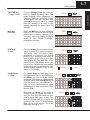
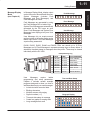
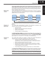
Bit Control Mode temporarily reassigns eight keys on the keypad for dedicated
control of eight I/O bits. A Setup Parameter is required. In the drawing below, the
setup parameter points to a system I/O location for either X, Y, C, or GX type I/O
points. This example’s setup parameter points to a control relay location, controlling
the first eight relays. The keypad switches operate as momentary, normally open
switches. When ladder logic uses these bit control I/O points as inputs, keypad
entries can request I/O bits to turn on as long as keys are pressed.
V–Memory Space
User V-memory
Setup Parameters
READ
System I/O
X
Y
C
GX
WRITE
While the keypad is in Bit Control Mode, the display may be in either Message
Display, Status Display, or Change Preset Mode.
WARNING: Bit Control Mode is designed for debug purposes only. There is no
automatic indication that normal keypad functionality has been suspended.
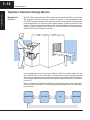
With a simple parameter setup and ladder
program, you can use Bit Control Mode to
turn on an output module’s output points.
In the example system to the right, the
eight keys shown from the keypad have
been configured to turn on control relays
C0 through C7. Then the main ladder
program uses these to turn on outputs Y0
through Y7.
C0
C1
C2
C3
C4
C5
C6
C7
8 pt
Input
8 pt
8 pt
Input Output
Getting Started
Bit Control Mode
(see Chapter 7)