1
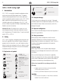
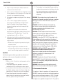
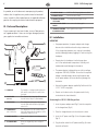
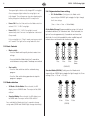
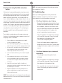
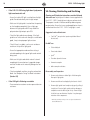
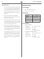
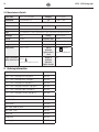
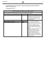
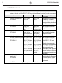
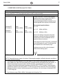
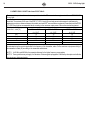
Federal Law restricts this device to sale by or on the order of a dentist. TABLE OF CONTENTS I. Introduction 4 II. Safety 4 III. Parts and Descriptions 6 IV. Installation 6 V. Operations and Controls 7 VI. Troubleshooting 9 VII. Cleaning, Disinfecting and Sterilizing 10 VIII. Technical Details 12 IX. General Information 13 X. Ordering Information 14 XI. Electromagnetic Compatibility 15 4 S.P.E.C. 3 LED Curing LIght EN S.P.E.C. 3 LED Curing Light I. Indication For Use: This product can be used for intra- and extra-oral polymerization of visible light cured dental materials with Camphorquinone (CQ) photoinitiators. The peak wavelength output is 455 nm – 465 nm. Relative Humidity 10% 106 kPa Atmospheric Pressure 80 kPa 2.2. Transport damage Check the device for any damage after receiving it. If damaged, immediately report to the transportation company within 24 hours from the date of receipt. Under no circumstances, work with a damaged curing light. 2.3. Operator’s obligations Users must be trained and comply with state or local regulations in force for this type of device. 2.4. Safety instructions II. Safety S.P.E.C. 3 LED Curing Light is designed and manufactured in conformity with applicable safety standards. To prevent damage to equipment and risks for patients, users, and third parties, please follow the safety notes and operate with care. Liability can not be accepted for damage resulting from misuse or failure to operate in compliance with the safety notes. 2.1. Explanation of symbols Direct Current CAUTION Consult accompanying documents Manufacturer ELECTRIC SHOCK Caution for electric shock. Risk of fatal injury if instructions are not followed. NOTE Consult Instructions For Use Keep dry 85% % Non-Ionizing Radiation S.P.E.C. 3 LED is a curing light intended for rapid polymerization of light-cured materials by dental professionals. This product effectively reduces polymerization time on various light-cured materials and provides excellent treatment results. S.P.E.C. 3 LED’s body is made from industrial-grade aluminum which ensures its durability and excellent heat dissipation. The S.P.E.C. 3 LED features multiple curing modes (3K Mode, Standard Mode, Ortho Mode) for maximum functionality. Serial No. Temperature Limitation -5˚C 23˚F Introduction Manufacturer date 40˚C 104˚F Type B applied part Level of protection against electric shock. Before putting the device into operation, read this manual thoroughly and follow the instructions to avoid any misuse or damage especially related to user and patient’s health. Do not use this device without proper eye protection for the operator, assistant and patient. ELECTRIC SHOCK Before using the device, check the power cord and plug for damage. If they are damaged, do not connect the machine to the mains power. Only use authorized spare parts and accessories supplied by Coltène. Use of parts other than those recommended may damage circuitry and will void product warranty. Repair or disassembly of this device must be done by authorized personnel only. Coltène is not responsible for any damage caused by the following: • Improper repair or maintenance service performed by unauthorized personnel or facilities. • Use of any unauthorized replacement parts or accessories. Fragile Unstable Use no hooks / Do not puncture Class II Equipment Double Insulated Equipment Do not look directly into light emitted from LED CAUTION A.Do not immerse the product in water. Moisture should be avoided. Electric shock could occur. Owner’s Guide B.Keep it in a dry and clean place. Exposure to moisture increases the risk of electric shock. C.After use, place the handpiece on the charger base securely. Failure to properly secure the handpiece in the charger base may result in an incomplete battery charge. D.Do not drop the handpiece or light guide. Device damage may occur. E. S.P.E.C. 3 LED Curing Light produces high-output light energy. Do not look directly at the light emitted from this curing light. Persons having a history of photosensitizing drugs should not be exposed to light from this light. F.This product can be used for intra- and extra-oral polymerization of visible light cured dental materials with camphorquinone (CQ) photoinitiators. The peak light wavelength output is 455 nm – 465 nm. G.Light output from this light may be significantly increased compared to other polymerization devices; therefore when using this device: 1. Determine the curing time of your material using the enclosed test block. 2. Adjust curing techniques in accordance with the increased energy. Pulpal and soft tissue damage may occur if excessive energy is applied to a restoration. CAUTION Avoid electromagnetic radiation generated from other electrical appliances, as they may cause the product to malfunction. 2.5. Safety Notes 1.Before use, check if the device is working properly and has no visible damage. 2.The fiber-optic light guide is provided in a non-sterile condition and must be sterilized prior to patient contact. 3.In case of device malfunction, discontinue use and refer to the ‘Trouble shooting’ section in this Owner’s Guide. If the problem persists, contact our service center immediately. 4.Do not attempt to repair, disassemble or remodel this product without the manufacturer’s permission (Coltène). Otherwise, product warranty will be voided. 5 EN 5.The handpiece is not autoclavable. Do not sterilize the handpiece by immersion or heat sterilization such as dry heat, steam under pressure, or unsaturated chemical vapor (fiber-optic light guide and light shield can be autoclaved). WARNING: Take caution when using this product in the presence of a flammable anesthetic mixture or an oxidizer like oxygen or nitrous oxide. This device may act as an ignition source. WARNING: DO NOT look directly into the light output. Patient, clinician and assistants should wear UV orange eye protection when this device is in use. Retinal damage may occur. WARNING: DO NOT expose soft oral tissues at close proximity or burns may occur. Maintain a safe distance between the light guide tip and the soft tissue. WARNING: If using the S.P.E.C. 3 LED Curing Light in the Standard Mode and in close proximity of the gingival tissue, DO NOT expose tissue for more than 20 seconds or minor burns may occur. If longer curing time is required, consider a dual-cure product (composite or adhesive). Irradiance output in High Power Mode is 1600 mW/cm². WARNING: In 3K Mode, DO NOT expose soft tissue for more than 9 seconds or burns may occur. If a longer cure is needed, consider a dual-cure product (composite or adhesive). Irradiance output in 3K Mode is 3000 mW/cm². WARNING: Using barrier sleeves will reduce the light output by 5-10%. Due to the high output power of the S.P.E.C. 3 LED Curing Light, curing has been shown to be substantially equivalent. WARNING: Barrier sleeves are single patient use only. Barrier sleeve must be used to maintain proper hygiene. 2.6 Environment Protection This appliance is labeled in accordance with European directive 2002/96/EC concerning used electrical and electronic appliances (waste electrical and electronic equipment – WEEE). This guideline determines the framework for the return and recycling of used appliances as applicable throughout the EU. The symbol on 6 S.P.E.C. 3 LED Curing LIght EN the product, or on the documents accompanying the product, indicates that this appliance may not be treated as household waste. Instead it shall be handed over to the applicable collection point for the recycling of electrical and electronic equipment. III. Parts and Descriptions As you remove each item from the box, ensure all box contents are in good condition. If items are missing or damaged, contact your supplier for immediate assistance. 7. OWNER’S GUIDE S.P.E.C. 3 LED Curing Light Owner’s Guide. 8. BARRIER SLEEVES Use for infection control. 9. COMPOSITE CURING TEST BLOCK Test curing times and depth of cure. 10. P HILLIPS HEAD SCREW DRIVER Use to remove the battery pack. 11. H ANDPIECE COVERED BY BARRIER SLEEVE Place Light Shield over both. IV. Installation IMPORTANT 4 3 • For proper operation, the power adapter and charger base must be installed and used in a dry environment. If the charger base becomes wet, unplug it immediately and dry thoroughly before plugging it in and inserting the handpiece. • Do not place the handpiece into the charger base until it has reached room temperature. Humidity and condensation could damage the electronics. • The power adapter is designed for use within a voltage range from 100-240V, 50-60Hz. Ensure that the required voltage is available before connecting the power cord to the power adapter. Failure to do so may damage the electronics. • Use only the power adapter supplied by Coltène with the S.P.E.C. 3 LED Curing Light. • Do not use the device unless the power cord is firmly inserted into the electrical outlet. 2 5 1 6 8 7 Owner’s Guide 9 10 11 1. HANDPIECE 2. LIGHT GUIDE (8MM TURBO) 3. LIGHT SHIELD 4. CHARGER BASE The handpiece is equipped with high-power LEDs and its control panel is located on the front part. The output of the Curing Light LED is emitted from the end of this piece (autoclavable). This shield protects the eyes of the operator from the light emitted from the light guide when in use. Connecting the S.P.E.C. 3 LED Charger Base: 1.Insert the power adapter cord (Fig. 5) into the receptacle in the charger base (Fig. 4). The charger base is for the cordless curing light only. Always place the handpiece on the charger base when not in use. 2.Place the charger base on a level and secure surface. 5. POWER ADAPTER Please use the original power adapter at all times. 3.Insert the AC power cord (Fig. 6) into the power adapter (Fig. 5). 6. AC POWER CORD Please use original AC power cord (at all times). (S.P.E.C. 3 – 6V DC, 2.5A) 4.Plug the other end of the AC power cord (Fig. 6) into an electrical wall outlet. extreme temperatures or open fire. Operate in ambient temperatures. (recommended temperature: -5°C ~ +40°C (23°F ~ 104°F). Malfunction may occur. • Charging the battery pack: • The handpiece should be placed on the charger base when battery is low or not in use. • efore using the S.P.E.C. 3 LED Curing Light for the first B time, please charge its battery for 24 hours. • Make sure the handpiece is properly connected and placed on the charger base. Do not force fit. • When the battery is low or discharged, the handpiece will not operate or maintain low power output. Place the handpiece on the charger base immediately for 2-3 hours before attempting to use. • Charging in progress: RED light is ON • Charging complete: GREEN light is ON Check the device components thoroughly before use. - Ensure no components are damaged or deformed. - Ensure the main plug and the electrical outlet socket are compatible. - Check to see if the power cord is damaged. • When the battery level is critical, the LED display will turn to ORANGE and start blinking: Please fully recharge the S.P.E.C. 3 LED handpiece by placing the handpiece on the charger base for 2-3 hours. Failure to fully recharge may reduce battery life. • Built-in automatic cool-down protection mode: The S.P.E.C. 3 LED handpiece will not function if its surface temperature is above 45°C (113°F) for user’s safety. The light will flash alternately between green and orange in the cool-down protection mode. Place the handpiece into the charger base and allow the light to cool down for 5 minutes then try again. NOTE: Do not operate the device while being charged on the charger base. 4.1. Installation procedure 2. Place the barrier sleeve over the curing light. Put the light shield over the end of the light guide drawing the barrier sleeve taut. 3. Plug the AC power cord into the receptacle in the power adapter. 4. Connect the S.P.E.C. 3 LED Charger Base to the power adapter. Insert the plug on the power adapter completely into the wall electrical outlet. 5. Keep the handpiece on the charger base when not in use. CAUTION • If the light shield obstructs view of the restoration, UV eye protection may be worn as an alternate means of protection. • Do not expose the device or the power supply to V. Operations and Controls Control Panel 15 Gently insert the light guide into the opening on the handpiece. When light guide is fully inserted, approximately 1mm of the metal ring will be exposed. OM 1. T he S.P.E.C. 3 LED Curing Light will only function properly if all of its components are in good operating condition. Shot switch 5.1. Powering ON and OFF • The battery charge level display: 5 5.Insert the handpiece into the charger base. Verify that the charger base LED is illuminated red which indicates that the device is charging. An illuminated green LED indicates the light is fully charged. 7 EN 10 Owner’s Guide Mode switch 8 S.P.E.C. 3 LED Curing LIght EN Three green lights indicate a fully charged LED curing light. One or two green lights indicate the curing light is not fully charged. The unit beeps one time after displaying the battery charge level indicating the LED is ready to use. • P ower ON: Press the Shot switch or the Mode switch to activate S.P.E.C. 3 LED Curing Light. • Power OFF: S.P.E.C. 3 LED Curing Light turns off automatically after 5 minutes if no operation is detected (Sleep mode). If the curing light is in ”Sleep” mode, pressing any switch will “awaken” the light to the curing mode last used. 5.4. Polymerization time setting • 3 K / Ortho Mode: Quickly press the Mode switch sequentially on ORANGE light to toggle the light through the 4 time settings (1sec. ➝ 2sec ➝ 3sec. ➝ Ortho Mode). Ortho Mode (Orange) Recommended for curing a full arch of orthodontic brackets, or 16 brackets total. When activated, the light will cure for approximately 3 seconds for each mesial or distal side. A visual half-second blink and an audible beep will indicate when each bracket side has been cured. 5.2. Basic Controls • Mode switch: - Press the Mode switch quickly to select various time settings. - Press and hold the Mode Switch for 3 seconds to switch between curing modes. Two beeps are emitted. • Shot switch: - Press the Shot switch to start the selected curing program. - Press the Shot switch during operation to stop the program in progress. OM OM OM OM 15 3 15 3 15 3 15 3 10 2 10 2 10 2 10 2 5 1 5 1 5 1 5 1 1 Sec. 2 Sec. 3 Sec. Ortho Mode (ORANGE) Standard Mode (GREEN): Quickly press the Mode switch sequentially on GREEN light to toggle the light through the 3 time settings (5 sec. ➝ 10 sec. ➝ 15 sec.). 5.3. Mode selection • • 3 K Mode / Ortho Mode: When selected, the LED display turns to ORANGE color. The output will be 3000 mW/cm². OM OM OM 15 3 15 3 15 3 10 2 10 2 10 2 5 1 5 1 5 1 S tandard Mode: When selected, the LED display turns to GREEN color. The output will be 1600 mW/cm². Press and hold the Mode switch for 3 seconds to change curing mode (GREEN and ORANGE light changes alternately). 5 Sec. 10 Sec. (GREEN) 15 Sec. Owner’s Guide 9 EN 5.5. Composite Curing Test Block Instructions For Use NOTE: Light output from accessory light guides may vary from the standard 8mm Turbo Tip, Manufacturer’s recommended composite curing times are typically based on curing 2mm increments with a minimum acceptable visible light output of 300 mW/cm2. For curing lights that provide significantly higher output, the test block enables the user to evaluate high power curing and adjust either the time or increment thickness based on the results. In general, the required curing energy is a constant function of the light output and time (mW/cm2 x sec). Changes in one factor can be offset by a djusting the other. As an example, doubling the light output (mW/cm2) may reduce the curing time (sec) by half. This relationship can be used as a guideline for establishing composite curing test parameters. VI. Troubleshooting Please try the following procedures to rectify the common problems listed below. Contact the manufacturer’s customer service department for all other problems encountered. • The test block is used to determine the curing rate at varying thickness, of a selected combination of composite material and curing light. To use the test block: 1.Place the block on a mixing pad or similar smooth surface, test (bottom) side down. 2.Fill a selected opening (typically the 2 mm deep hole), flush to the top surface, with the composite to be tested. 3.For best results, cover both sides of the filled opening with a clear plastic matrix strip to eliminate the air inhibited layer common with resin curing. 4.Cure the material, from the top, for a chosen length of time. 5.After removing any clear matrix, check the hardness of the cured composite from the bottom by scraping the surface with a tungsten carbide carver or similar instrument. 6.Inspect this cured surface. Ideally, it should resist indentation and there should be no soft material that can be removed by the instrument. 7.Repeat the procedure as necessary to determine an optimum combination of curing time and increment thickness for the material. NOTE: Darker shades within a line of composites normally require additional curing time. Please refer to the material manufacturer’s instructions for use. If the Shot or Mode button doesn’t light up - Removing the battery pack and reinserting it will reset the device to its original factory settings. On the base of the handpiece, remove the two miniature screws with the enclosed phillips head screw driver provided. Slide the battery pack out of the handpiece and reinsert it, replacing the two miniature screws. - Place the handpiece on the charger base to recharge until the red light changes to the green illuminated light indicating a fully charged curing light. This will resolve a low-power problem. - Ensure that the power adapter is plugged into the charger base securely. Ensure that the AC power cord is plugged into the power adapter and the wall outlet securely. • If the Shot or Mode button lights up but doesn’t work properly - The curing light may be discharged and needs recharging. - Place the handpiece on the charger base to recharge until the red light changes to the green illuminated light indicating a fully charged curing light. - If the curing light does not activate, the unit requires service. Please contact your supplier or authorized service center. 10 S.P.E.C. 3 LED Curing LIght EN • If the S.P.E.C. 3 LED Curing Light doesn’t polymerize light-cured materials well - Ensure that a blue LED light is emitted from the light guide. Do not look directly into the light output. - Make sure the light guide is inserted into the opening on the handpiece completely. Even a slight gap between the light guide and LED may reduce the polymerization light output up to 50%. - Check the light guide for any damage. If the light guide has an inner crack even though its surface looks good, it may interrupt proper light emission. - Check if there’s any debris, such as resin residue or sealant on the tip of the light guide. Cleaning and Disinfection Instructions must be followed after each use. Polyethylene film barrier sleeves supplied with the S.P.E.C. 3 LED Curing Light are single use and non-sterile. The purpose is to aid in infection control by addressing cross contamination. Ensure that a new undamaged barrier sleeve is installed each time the S.P.E.C. 3 LED Curing Light is used. Suggested surface disinfectant: • aviCide®* (or equivalent quaternary/alcohol blend C disinfectant) Do NOT use: • Glutaraldehyde - Ensure that appropriate mode and time setting is selected according to the type of light-cured material being used. • Denatured alcohol • Lysol®* - Make sure the light cured dental material is stored according to the manufacturer’s suggested storage and that the date on the material’s package has not expired. • Phenol or phenolic cleaner • Ammonia complex • Iodine complex solutions - Check curing depth and time using the enclosed test block. See Composite Curing Test Block Instructions. (Section 5.5) • VII. Cleaning, Disinfecting and Sterilizing If the LED light is flickering or unstable - Please contact our customer service representative for assistance. Disassembly and Inspection: 1.Remove red elastomer rubber light shield from glass fiber-optic light guide. 2.Remove and discard used polyethylene barrier shield. 3.Remove light guide from handpiece by gently pulling it straight out. Examine light guide ends for damage or composite material adhering to the tip. Examine light shield for tears or distortion. Replace if any damage is noted on either component. * CaviCide®, CaviWipes® and Lysol® are not registered trademarks of Coltène/Whaledent Inc. Owner’s Guide Handpiece and Charger Base Cleaning: 1.Initial cleaning of handpiece must begin immediately after use to prevent drying of soil and contaminants in and on the device. 2.All exterior surfaces of the handpiece or charger base may be wiped with CaviWipes®* or a cloth soaked in surface disinfectant to remove gross soil. Do not allow cleaning solution to invade the interior of these components since this may adversely affect the electronics. Disinfecting: 1.All exterior surfaces of the handpiece or charger base must be wiped and wetted with CaviWipes®* or a cloth soaked in surface disinfectant. 2.Allow the CaviCide®* surface disinfectant to reside on the surface for a minimum of 3 minutes. Do not allow the disinfectant to dry on the surface. Rinsing: 1.Using clean tap water on a clean cloth, wipe away residual disinfectant. Drying: 1.Use a clean dry cloth to dry the exterior surfaces. Do not allow fluids to accumulate in the charger base socket as this may adversely affect the electronics. Light Guide (fiber optic glass) Cleaning: 1.Initial cleaning of the fiber optic light guide must begin immediately after use to prevent drying of soil and contaminants in and on the device. 2.All exterior surfaces may be wiped with CaviWipes®* or a cloth soaked in surface disinfectant to remove gross soil. Use a soft brush to remove contaminants in the junction between the glass rod and metal ferrule if necessary. 11 EN 3.Clean thoroughly using an ultrasonic cleaner such as the Coltène/Whaledent BioSonic® Ultrasonic Cleaning System with BioSonic® UC32 Solution Concentrate or equivalent. Minimum cycle time 10 minutes. Sterilizing: Package in a FDA cleared wrap prior to sterilization. Sterilization can be performed with either of the following cycles; 1.In a gravity autoclave at 132°C / 270°F for 15 minutes with a 15 – 30 minute drying time. 2.In a pre-vacuum sterilizer at 132°C / 270°F for 4 minutes with a 20 – 30 minute drying time. Light Shield (Elastomer Rubber) Cleaning: 1.Initial cleaning of the light shield must begin immediately after use to prevent drying of soil and contaminants in and on the device. 2.All exterior surfaces may be wiped with CaviWipes®* or a cloth soaked in surface disinfectant to remove gross soil. Examine the light shield for damage and discard if any cuts, tears, or distortion is noted. 3.Clean thoroughly using an ultrasonic cleaner such as the Coltène/Whaledent BioSonic® Ultrasonic Cleaning System with BioSonic® UC32 Solution Concentrate or equivalent. Minimum cycle time 10 minutes. 4.The elastomer rubber light shield can be cleaned, sterilized and reused up to 5 times, discard after that. Sterilizing: Package in a FDA cleared wrap prior to sterilization. Sterilization can be performed with either of the following cycles; 1.In a gravity autoclave at 132°C / 270°F for 15 minutes with a 15 – 30 minute drying time. 2.In a pre-vacuum sterilizer at 132°C / 270°F for 4 minutes with a 20 – 30 minute drying time. 12 S.P.E.C. 3 LED Curing LIght EN Reassembly & Storage 1.After all parts have been allowed to dry completely, gently insert the metal end of the glass fiber optic light guide into the circular opening of the handpiece. Make sure the light guide is completely inserted until it stops. This will position the light guide properly with the internal LED light source. VIII.Technical Details 8.1. Power Supply A. Input: 100V – 240V AC / 50 ~ 60 Hz B. Output: S.P.E.C. 3: 6V DC, 2.5A 8.2. Dimensions 2.Slip the entire assembly into a new undamaged polyethylene film barrier sleeve. Be careful not to cause damage to the barrier sleeve film. Component S.P.E.C. 3 Curing Light Handpiece 174.5 × 24.8 (mm) Power Adapter 47 × 87 × 32 (mm), 3.Fold the end of the barrier sleeve film over the tip of the fiber optic light guide making sure the seam in the barrier sleeve does not pass across the light exit face of the light guide. This will allow optimum light output. Charger Base 136 × 86 × 60 (mm), AC Power Cord 1.3M 4.Insert an elastomer rubber light shield over the end of the fiber optic light guide. This will hold the polyethylene barrier sleeve taut over the tip of the light guide and hold it in place ready for the next use. 5.Verify the polyethylene film barrier sleeve is still intact and has not suffered damage such as tears or cuts. Store the reassembled S.P.E.C. 3 LED Curing Light in a clean dry location, preferably on the S.P.E.C. 3 LED charger base so that the battery will be completely charged prior to the next use. 8.3. Environment A. Operating Conditions B. Temperature: -5°C ~ +40°C (23°F ~ 104°F) Relative Humidity: 10% ~ 85% Ambient Pressure: 80 ~ 106 kPa (23.62 inHg ~ 31.30 inHg) Transportation and Storage Conditions Temperature: -10°C ~ +45°C (14°F ~ 113°F) Relative Humidity: 10% ~ 90% Ambient Pressure: 60 ~ 106 kPa (17.72 inHg ~ 31.30 inHg) Owner’s Guide IX. General Information 9.1. Warranty information Our products are carefully manufactured to meet stringent quality assurance requirements. Our products are manufactured from new parts or new and serviceable used parts. Regardless, our warranty terms apply. This product has been developed specifically for use in dentistry and is intended to be operated only by qualified dental professionals in accordance with the instructions contained in this guide. However, notwithstanding anything contained herein to the contrary, the user shall at all times be solely responsible for determining the suitability of the product for the intended purpose and the method of its use. Any guidance on application technology offered by or on behalf of the manufacturer, whether written, verbal or by demonstration, shall not relieve the dental professional of his/her obligation to control the product and to make all professional judgments regarding its use. Our products are warranted in accordance with the terms of a written Certificate of Limited Warranty accompanying each product. Except for the warranties specifically set forth in the Certificate of Limited Warranty, Coltène/Whaledent Inc. provides no warranties or guarantees of any kind covering the product, expressed or implied, including, without limitation, any warranties as to merchantability or fitness for a particular purpose. The purchaser/user is referred to the Certificate of Limited Warranty for all of the terms, conditions and limitations of the warranty covering this product. This Section of the user manual is not intended to in any way modify or add to the warranty provided in the Certificate of Limited Warranty. Any claim for damage or breakage to the product in transit should be made to the carrier promptly upon discovery. Coltène/ Whaledent Inc. does not warrant the product against shipping damage. EN 13 14 S.P.E.C. 3 LED Curing LIght EN 9.2. Manufacturer’s Details Product name S.P.E.C. 3 LED Curing Light Manufacturer Coltène/Whaledent Inc. Address 235 Ascot Parkway, Cuyahoga Falls, OH 44223 / USA EU Representative Coltène/Whaledent GmbH + Co. KG Address Raiffeisenstrasse 30, 89129 Langenau / Germany Usage This medical device is used for polymerization of light cured material by dental professionals. Net Weight 125g Serial No. See label Operation Refer to user guide Precaution Storage Refer to user guide Input power Output power S.P.E.C. 3: 15W Degree of protection against electric shock Type (B) Level of protection against electric shock Category L.E.D. Curing Light Tel + 1 800 221 3046 Tel Packing Production Date Type of protection against electric shock Degree of protection against the ingress of water X. Ordering Information Product Description Catalog # S.P.E.C. 3 LED Curing Light USA Plug Type A 60013941 S.P.E.C. 3 LED Curing Light EURO Plug Type C 60013942 S.P.E.C. 3 LED Curing Light UK Plug Type A G 60013943 S.P.E.C. 3 LED Curing Light Australian Plug Type IA 60013944 S.P.E.C. 3 LED Curing Light Japan Plug Type AJ 60013945 S.P.E.C. 3 LED Curing Light Chinese Plug Type CH 60013946 Light Shield, 8mm 60013948 Light Shield, 11mm 60014360 Barrier Sleeves 60013949 Light Guide, Turbo-Tip, 8mm 60013950 Light Guide, 11mm 60013951 Battery Pack 60013952 Charger Base 60013953 Power Supply 60013955 +49 (0)7345 805 0 1 LED Curing Light See label Refer to user guide AC 100~240V, 60Hz, 50Hz Class II Equipment Double Insulated Equipment IPXO Owner’s Guide EN XI. The following are guidance and manufacturer’s declarations regarding electromagnetic compatibility for the SPEC 3™ LED Curing Light. 11.1 EN/IEC 60601-1-2 Table 1 Guidance and Manufacturer’s Declaration – Electromagnetic Emissions The SPEC 3™ LED Curing Light is intended for use in the electromagnetic environment specified below. The customer or the end user of the SPEC 3™ LED Curing Light should assure that it is used in such an environment. Emissions test Compliance Electromagnetic environment - guidance RF emissions CISPR 11:2004 Group 1 The SPEC 3™ LED Curing Light uses RF energy only for its internal function. Therefore, its RF emissions are very low and are not likely to cause any interference in nearby electronic equipment. RF emissions CISPR 11:2004 Class B The SPEC 3™ LED Curing Light is suitable for use in all establishments other than Harmonic emissions IEC 61000-3-2 Class A domestic, and may be used in domestic Voltage fluctuations/Flicker emissions IEC 61000-3-3 Complies establishments and those directly connected to the public low-voltage power supply network that supplies buildings for domestic purposes, provided the following warning is heeded: Warning: This equipment is intended for use by healthcare professionals only. This equipment may cause radio interference or may disrupt the operation of nearby equipment. It may be necessary to take mitigation measures such as re-orienting or relocating the SPEC 3™ LED Curing Light or shielding the location. 15 16 EN S.P.E.C. 3 LED Curing LIght 11.2 EN/IEC 60601-1-2 Table 2 Guidance and Manufacturer’s Declaration – Electromagnetic Immunity The SPEC 3™ LED Curing Light is intended for use in the electromagnetic environment specified below. The customer or the end user of the SPEC 3™ LED Curing Light should assure it is used only in such an environment. Immunity Test IEC60601 test level Compliance Level Intended Electromagnetic Environment Electrostatic discharge (ESD) ± 6kV contact ± 6kV contact Floors should be wood, concrete IEC 61000-4-2 ± 8kV air ± 8kV air or ceramic tile. If floors are covered with synthetic material, the relative humidity should be at least 30%. Electrical fast transient/burst ±2kV for power ±2kV for power Mains power quality should be IEC 61000-4-4 supply lines supply lines that of a typical commercial or ±1kV for input/output ±1kV for hospital environment. lines input/output lines Surge ±1kV differential ±1kV differential Mains power quality should be IEC 61000-4-5 mode (line-line) mode (line-line) that of a typical commercial or ±2kV common mode ±2kV common hospital environment. (line-earth) mode (line-earth) Mains power quality should be <5% UT (>95% dip Voltage dips, short interruptions <5% UT (>95% dip that of a typical commercial or in UT) for 0.5 cycle and voltage variations on power in UT) for 0.5 cycle hospital environment. If the user supply input lines of the SPEC 3™ LED Curing 40% UT (60% dip IEC 61000-4-11 40% UT (60% dip in Light requires continued in UT) for 5 cycles UT) for 5 cycles operation during power mains interruptions, it is recommended 70% UT (30% dip 70% UT (30% dip in in UT) for 25 cycles that the SPEC 3™ LED Curing UT) for 25 cycles Light be powered from an uninterruptible power supply with <5% UT (>95% dip <5% UT (>95% dip sufficient capacity to run the unit in UT) for 5 in UT) for 5 seconds for the maximum required time of seconds interruption. Power frequency (50/60Hz) 3A/m 3A/m Power frequency magnetic fields magnetic field should be at levels characteristic IEC 61000-4-8 of a typical location in a typical commercial or hospital environment. Note UT is the a.c. mains voltage prior to application of the test level. Owner’s Guide 17 EN 11.3 EN/IEC 60601-1-2:2007 Sub-clause 5.2.2.2 Table 4: Guidance and Manufacturer’s Declaration – Electromagnetic Immunity The SPEC 3™ LED Curing Light is intended for use in the electromagnetic environment specified below. The customer or the end user of the SPEC 3™ LED Curing Light should assure it is used in such an environment. Immunity Test IEC60601 test level Compliance Level Intended Electromagnetic Environment Portable and mobile RF communications equipment should be used no closer to any part of the SPEC 3™ LED Curing Light, including cables, than the recommended separation distance calculated from the equation applicable to the frequency of the transmitter. Conducted RF IEC 61000-4-6 3Vrms 150kHz to 80MHz 3Vrms 150kHz to 80MHz Radiated RF IEC 61000-4-3 3V/m 80MHz to 2.5GHz 3V/m 80MHz to 2.5GHz Recommended separation distance d = 1.2√P d = 1.2√P 80MHz to 800 MHz d = 2.3√P 800MHz to 2.5GHz where P is the maximum output power rating of the transmitter in watts (W) according to the transmitter manufacturer and d is the recommended minimum separation distance in meters (m). Field strengths from fixed RF transmitters, as determined a by an electromagnetic site survey , should be less than b the compliance level in each frequency range. Interference may occur in the vicinity of equipment marked with the following symbol: NOTE 1 At 80MHz and 800MHz, the higher frequency range applies NOTE 2 These guidelines may not apply in all situations. Electromagnetic propagation is affected by absorption and reflection from objects, structures and people. a Field strengths from fixed transmitters, such as base stations for radio (cellular/cordless) telephones and land mobile radios, amateur radio, AM and FM radio broadcast and TV broadcast cannot be predicted theoretically with accuracy. To assess the electromagnetic environment due to fixed RF transmitters, an electromagnetic site survey should be considered. If the measured field strength in the location in which the SPEC 3™ LED Curing Light is used exceeds the applicable RF compliance level above, the SPEC 3™ LED Curing Light should be observed to verify normal operation. If abnormal performance is observed, additional measures may be necessary, such as re-orienting or relocating the SPEC 3™ LED Curing Light. b Over the frequency range 150kHz to 80MHz, field strengths should be less than 3V/m. 18 EN S.P.E.C. 3 LED Curing LIght 11.4 EN/IEC 60601-1-2:2007 Sub-clause 5.2.2.2 Table 6: Recommended separation distances between portable and mobile RF communications equipment and the SPEC 3™ LED Curing Light. The SPEC 3™ LED Curing Light is intended for use in an electromagnetic environment in which radiated RF disturbances are controlled. The customer or the user of the SPEC 3™ LED Curing Light can help prevent electromagnetic interference by maintaining a minimum distance between the portable and mobile RF communications equipment (transmitters) and the SPEC 3™ LED Curing Light as recommended below, according to the maximum output power of the communications equipment. Rated maximum output power of Separation distance according to frequency of transmitter in meters (m) transmitter in watts (W) 150kHz to 80MHz 80MHz to 800MHz 800MHz to 2.5GHz d = 1.2√P d = 1.2√P d = 2.3√P 0.01 .12 .12 .23 0.1 .38 .38 .73 1.0 1.2 1.2 2.3 10 3.8 3.8 7.3 100 12 12 23 For transmitters rated at a maximum output power not listed above, the recommended separation distance d in meters (m) can be estimated using the equation applicable to the frequency of the transmitter, where P is the maximum output power rating of the transmitter in watts (W) according to the transmitter manufacturer. NOTE 1 At 80 MHz and 800 MHz, the separation distance for the higher frequency range applies. NOTE 2 These guidelines may not apply in all situations. Electromagnetic propagation is affected by absorption and reflection from structures, objects and people. Copyright © 2012 Coltène/Whaledent, Inc. All rights reserved worldwide. 9.24.2012 Coltène/Whaledent AG Feldwiesenstrasse 20 9450 Altstätten / Switzerland Tel. +41 (0)71 757 53 00 Fax +41 (0)71 757 53 01 [email protected] Authorized EU Representative: Coltène/Whaledent GmbH + Co. KG Raiffeisenstrasse 30 89129 Langenau / Germany Tel. +49 (0)7345 805 0 Fax +49 (0)7345 805 201 [email protected] coltene.com P/N 40001378B Manufactured for: Coltène/Whaledent Inc. 235 Ascot Parkway Cuyahoga Falls, OH 44223 / USA Tel. USA & Canada + 1 800 221 3046 + 1 330 916 8800 Fax +1 330 916 7077 [email protected]